Westermo TDW-33 User Manual
Din-rail tele v.90 modem
Hide thumbs
Also See for TDW-33:
- User manual (21 pages) ,
- User manual (29 pages) ,
- Commands interface manual (84 pages)
Table of Contents
Advertisement
Quick Links
Download this manual
See also:
User Manual
Advertisement
Table of Contents

Related Manuals for Westermo TDW-33


Summary of Contents for Westermo TDW-33
- Page 1 User Guide 6619-2202 TDW-33 DIN-rail Tele V.90 modem www.westermo.com...
-
Page 2: Legal Information
Under no circumstances shall Westermo be responsible for any loss of data or income or any special, incidental, and consequential or indirect damages howsoever caused. -
Page 3: Care Recommendations
Do not use or store the unit in dusty, dirty areas, connectors as well as other mechanical part may be damaged. If the unit is not working properly, contact the place of purchase, nearest Westermo distributor office or Westermo Tech support. -
Page 4: Agency Approvals And Standards Compliance
(e.g., 03 is a REN of 0.3). For earlier products, the REN is separately shown on the label. If this equipment TDW-33 causes harm to the telephone network, the telephone company will notify you in advance that temporary discontinuance of service may be required. But if advance notice isn't practical, the telephone company will notify the customer as soon as possible. -
Page 5: Electrical Safety Advisory
If your home has specially wired alarm equipment connected to the telephone line, ensure the instal- lation of this TDW-33 does not disable your alarm equipment. If you have questions about what will disable alarm equipment, consult your telephone company or a qualified installer. -
Page 6: Declaration Of Conformity
Declaration of Conformity Westermo Teleindustri AB Declaration of conformity The manufacturer Westermo Teleindustri AB SE-640 40 Stora Sundby, Sweden Herewith declares that the product(s) Type of product Model Art no Installation manual 3619-0001 DIN-rail Tele modem TDW-33 6619-2201 is in conformity with the following EC directive(s). -
Page 7: Type Tests And Environmental Conditions
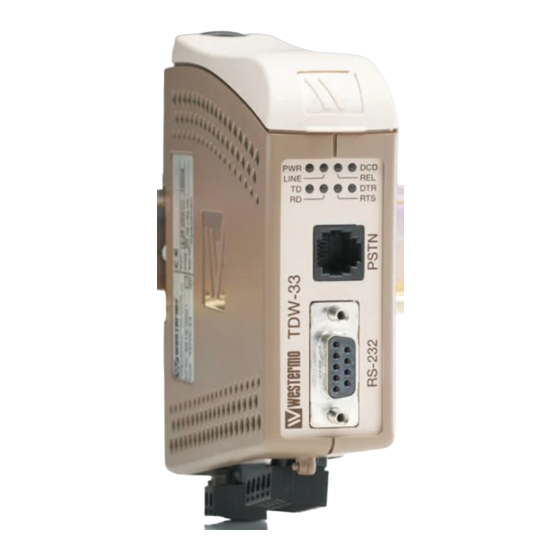
Type tests and environmental conditions Electromagnetic Compatibility Phenomena Test Description Test levels EN 61000-4-2 Enclosure contact ± 6 kV Enclosure air ± 8 kV RF field AM IEC 61000-4-3 Enclosure 20 V/m 80% AM (1 kHz), 80 – 2000 MHz modulated RF field 900 MHz ENV 50204... - Page 8 The modem has an RS-232 interface supporting terminal data rates up to 115 kbit/s. The TDW-33 is a V.90 modem meaning that it can support data rates of up to 56 kbit/s on the PSTN line side.
-
Page 9: Interface Specifications
Interface specifications Power LV Rated voltage 12 to 48 VDC or 12 to 34 VAC Operating voltage 10 to 60 VDC or 10 to 42 VAC Rated current 150 mA @ 12 VDC 70 mA @ 24 VDC 40 mA @ 48 VDC 150 mA @ 12 VAC 70 mA @ 24 VAC Rated frequency... - Page 10 RS-232 (DCE) Position D-sub D-sub Direction* Description description No. 1 Data Carrier Direct (DCD) LED Indicators No. 2 Received Data (RD) (for details see No. 3 Transmitted Data (TD) next page) No. 4 Data Terminal Ready (DTR) No. 5 – Signal Ground (SG) No.
-
Page 11: Led Indicators
LED Indicators Status Description No data Transmit data ON / FLASH The modem receiving data on the DTE interface No data Receive data ON / FLASH The modem transmitting data on the DTE interface RTS signal is inactive Request RTS signal is active to send DCD signal is inactive Data carrier... - Page 12 Mounting This unit should be mounted on 35 mm DIN-rail, which is horizontally mounted inside an apparatus cabinet, or similar. Snap on mounting, see figure. Cooling 10 mm * (0.4 inches) This unit uses convection cooling. To avoid obstructing the air- 25 mm flow around the unit, use the following spacing rules.
- Page 13 … Start a terminal emulation program (i.e. Windows Hyper-Terminal). … Configure the local modem data rate and word format. … Set up a connection to the remote TDW-33 to be configured by using the normal dial command: ATD<No><CR>. When connected send the remote escape sequence <++++>.
-
Page 14: Application Examples
AT&W Store default settings Set up the connection – The dialling modem AT&Z0=nnn Store the number of the remote modem in the dialling TDW-33 AT&S0 Set DSR signal always high (if this signal is used to trig the DTR) AT&B1... - Page 15 Below follows a list of commands that might resolve the problems. The commands may of course be placed on one single command line if desired. Configure the TDW-33 connected to the PLC AT&F Set the unit to factory default.
- Page 16 PSTN modem, but can be any of the PSTN, ISDN or GSM modem from the Westermo product range. The DTE serial speed between the PLC – TDW-33 and TD-36 – PC is assumed to be 9600 8N1 but can be chosen to fit the actual system requirement.
- Page 17 CONNECT 9600 TDW-33 dials +4670428000 The number programmed correspond- ing to the password is dialled, prefer- able it’s the number to the TD-36 CONNECT 9600 Connection is established between the PC at TD-36 and the PLC at TDW-33 6619-2202...
- Page 18 PSTN line with normal telephones which is preferred not to give a ring signal when the meter is read. The TDW-33 is configured to answer calls on the Caller ID received, the valid numbers to answer is programmed into the TDW-33. There exists a number of standards for send- ing Caller ID check which standard is used by your operator.
- Page 20 Phone +65 6743 9801 • Fax +65 6745 0670 E-Mail: sales@westermo.co.uk E-mail: sales@westermo.com.sg Westermo Data Communications GmbH Goethestraße 67, 68753 Waghäusel Tel.: +49(0)7254-95400-0 • Fax.:+49(0)7254-95400-9 E-Mail: info@westermo.de Westermo Teleindustri AB have distributors in several countries, contact us for further information.
Need help?
Do you have a question about the TDW-33 and is the answer not in the manual?
Questions and answers