Advertisement
Table of Contents
- 1 Important Safety Instructions
- 2 Certificate of Conformity
- 3 Table of Contents
- 4 Introduction
- 5 Front Panel Diagram
- 6 Back Panel Diagram
- 7 I/O Box Diagram
- 8 MIC Stand Mounting Procedure
- 9 Making Connections
- 10 Overcoming Feedback
- 11 Setup Diagrams
- 12 Specifications
- 13 Audio Path Diagram
- Download this manual
Advertisement
Table of Contents

Related Manuals for TC-Helicon VoiceSolo VSM-300 XT


Summary of Contents for TC-Helicon VoiceSolo VSM-300 XT
- Page 1 VSM-300 XT USER MANUAL...
-
Page 3: Important Safety Instructions
IMPORTANT SAFETY INSTRUCTIONS The lightning flash with an arrowhead symbol within an The exclamation point within an equilateral triangle is equilateral triangle, is intended to alert the user to the intended to alert the user to the presence of important presence of uninsulated “dangerous voltage”... -
Page 4: Certificate Of Conformity
IMPORTANT SAFETY INSTRUCTIONS EMC / EMI. This equipment has been tested and found to comply with the Certificate Of Conformity limits for a Class B Digital device, pursuant to part 15 of the FCC TC Electronic A/S, Sindalsvej 34, 8240 rules. -
Page 5: Table Of Contents
TABLE OF CONTENTS Important Safety Instructions ... .a Certificate of Conformity ....b Table of Contents .....3 Introduction . -
Page 6: Introduction
INTRODUCTION Welcome to VoiceSoloXT About TC-Helicon The TC-Helicon VoiceSoloXT VSM range of near field live monitoring speakers is a new concept in personal monitoring. TC-Helicon strives for excellence in all things related to vocals, and the VSM range builds upon the success and worldwide reputation of TC-Helicon's vocal expertise. - Page 7 INTRODUCTION Preliminary Recommendations The VoiceSoloXT VSM series of monitors are capable of very high sound pressure levels (SPLs) especially at the close range when integrated onto a microphone stand. They were designed this way to be able to be loud enough to compete with live acoustic drum kits.
-
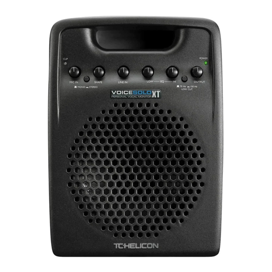
Page 8: Front Panel Diagram
FRONT PANEL DIAGRAM 1. CLIP LED 5. LINE IN level control This LED is a sum of clipping from the MIC, LINE and AUX This sets the gain for the line input. Adjust this so that only inputs. the loudest notes you play light the CLIP LED. 2. -
Page 9: Back Panel Diagram
BACK PANEL DIAGRAM 1. +20 dB button 4. LINE IN jack The +20 switch, when pushed in, adds more gain to your You may connect a mono line level signal through this jack dynamic mics that may produce lower output. When the such as an acoustic guitar pickup, guitar multi-effect, mono switch is out, it is possible to connect high output keyboard or an auxilliary send from your mixer. -
Page 10: I/O Box Diagram
I/O BOX DIAGRAM Inputs Pass Thrus All inputs and outputs are balanced but unbalanced cables These connections are used to send the individual inputs to and equipment may be used as well. separate channels in an external mixer. This type of connection is known as a passive splitter. - Page 11 MIC STAND MOUNTING 1. Separate the boom from the stand by unscrewing the VoiceSoloXT Placement Options boom from the vertical shaft of the microphone stand. To VoiceSoloXT can be placed in 4 different ways. This do this, tighten the clutch you use to raise and lower the versatility allows you to use it as a mic stand mounted stand first.
- Page 12 MIC STAND MOUNTING 3. Place VoiceSoloXT on the mic stand so the stand goes 5. Screw the Mic Boom Mount Attachment into your boom. into the hole on the bottom of the VoiceSoloXT. If you don’t need to mount VoiceSoloXT on a boom stand, you are finished with your setup.
-
Page 13: Mic Stand Mounting Procedure
MIC STAND MOUNTING 7. Your VoiceSoloXT should now look like this. 2. Still holding the boom so that it does not swing away, turn the lock nut counter-clockwise until it’s snug against the bottom of the boom. Note that it’s not possible to completely tighten the lock nut with your fingers, the final action is done by swinging the boom snug against the lock nut. -
Page 14: Making Connections
MAKING CONNECTIONS the OUTPUT level first then raise it carefully. You’re now Introduction ready to perform with VoiceSoloXT! The following paragraphs should be read at least once to learn more about safe and successful use of VoiceSoloXT. Using the I/O (Input and Output) Hooking up AC power connector box IMPORTANT - Before connecting the AC cable, confirm... -
Page 15: Overcoming Feedback
MAKING CONNECTIONS Plug into the Aux Input Overcoming feedback If you would like to blend your mic and instrument with, for As in any open speaker and mic combination, there is the example, a signal from another musician, a monitor send threat of feedback. -
Page 16: Setup Diagrams
SETUP DIAGRAMS Setup diagrams The following figures show a few of the many ways VoiceSoloXT can be used for monitoring or PA purposes. Fig. 1: The common monitor mix In this application you will use a single monitor mix containing several input sources from a mixing console as the input to the VSM-300XT. - Page 17 SETUP DIAGRAMS Fig. 3: Stereo PA/monitors with multiple inputs This small setup is good for a single performer who sings and plays to backing tracks. A guitar, a stereo MP3 player (or equivalent) and a mic all can be sent to the VSM-300XT. The MIX output of the VSM-300XT drives the LINE IN of the second VoiceSoloXT which becomes the stereo right speaker.
-
Page 18: Specifications
SPECIFICATIONS Audio Inputs All inputs and outputs are balanced (Onboard) ¼-inch Line input XLR with 42VDC phantom power and switchable sensitivity range 0db/+20db (I/O connector box) ¼-inch Line input (Left/Mono) ¼-inch Line input (Right) ¼-inch Aux input XLR Mic input with 42VDC phantom power Sensitivities: Mic input - (+20 dB switch out) +4 dBu to -23 dBu... -
Page 19: Audio Path Diagram
AUDIO PATH DIAGRAM...
Need help?
Do you have a question about the VoiceSolo VSM-300 XT and is the answer not in the manual?
Questions and answers