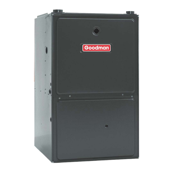
Goodman GMS95 Technical Information Manual
40" 95% gas furnaces
Hide thumbs
Also See for GMS95:
- Installation instructions manual (36 pages) ,
- Installation instructions manual (37 pages)
Advertisement
TECHNICAL INFORMATION MANUAL
GMS95
40" 95% Gas Furnaces
•
Refer to Service Manual RS660000x Rev. 1 for installa-
tion, operation, and troubleshooting information.
•
All safety information must be followed as provided in the
Service Manual.
•
Refer to the appropriate Parts Catalog for part number
information.
This manual is to be used by qualified HVAC technicians only. Goodman
does not assume any responsibility for property damage or personal injury
due to improper service procedures performed by an unqualified person.
Copyright © 2005 Goodman Manufacturing Company, L.P.
Model numbers
listed on page 3.
®
C
US
RT6612014 Rev. 1
November 2005
Advertisement
Table of Contents

Summary of Contents for Goodman GMS95
- Page 1 • Refer to the appropriate Parts Catalog for part number information. ® This manual is to be used by qualified HVAC technicians only. Goodman RT6612014 Rev. 1 does not assume any responsibility for property damage or personal injury November 2005 due to improper service procedures performed by an unqualified person.
-
Page 2: Product Identification
When engineering and manufacturing changes take place where interchangeability of components are affected, the manufacturing number will change. It is very important to use the model and manufacturing numbers at all times when requesting service or parts informa- tion. 95 070 3 B G: Goodman Revision ® or Distinctions A: Initial Release... - Page 3 OTHER FLAMMABLE LIQUIDS OR VAPORS IN THE VICINITY OF THIS APPLIANCE. DO NOT CONNECT TO OR USE ANY DEVICE THAT IS NOT DESIGN CERTI- FIED BY GOODMAN FOR USE WITH THIS UNIT. SERIOUS PROPERTY WARNING WARNING DAMAGE, PERSONAL INJURY, REDUCED UNIT PERFORMANCE AND/OR HAZARDOUS CONDITIONS MAY RESULT FROM THE USE OF SUCH NON- APPROVED DEVICES.
-
Page 4: Product Design
3. Conversion kits for high altitude natural or propane gas General Operation operation are available. See High Altitude Derate chart The GMS95 furnaces are equipped with an electronic igni- for details. tion device used to light the burners and an induced draft 4. -
Page 5: Component Identification
COMPONENT IDENTIFICATION Upflow /Horizontal Models 1 Gas Valve 19 Coil Front Cover Pressure Tap 2 Gas Line Entrance (Alternate) 20 Coil Front Cover Drain Port 3 Pressure Switch(es) 21 Drain Line Penetrations 4 Gas Manifold 22 Drain Trap 5 Combustion Air Intake Connection / “Coupling” 23 Blower Door Interlock Switch 6 Hot Surface Igniter 24 Capacitor... - Page 6 COMPONENT IDENTIFICATION GMS95*****XA DISCHARGE 28 3/4 DISCHARGE (DISCHARGE) 2 1/2 19 5/8 VENT/FLUE PIPE 2 1/16 2" PVC AIR INTAKE PIPE 2" PVC ALTERNATE 2 11/16 AIR INTAKE LOCATION ALTERNATE 7 3/8 GAS SUPPLY STANDARD GAS CONDENSATE HOLE SUPPLY HOLE DRAIN TRAP w/ 3/4"...
- Page 7 PRODUCT DESIGN PRESSURE SW ITCH TRIP P OINTS AND USAGE CHART NEGATIVE NEGATIVE NEGATIVE NEGATIVE PRESSURE SW ITCH TRIP POINTS AND USAGE PRESSURE PRESSURE PRESSURE PRESSURE ID BLOW ER ID BLOW ER COIL COVER COIL COVER 0 to 7,000 ft. 7,001 to 11,000 ft.
- Page 8 PRODUCT DESIGN ROLLOUT LIMIT SWITCHES 10123514 10123515 10123517 10123533 10123534 Part Number Open Setting (°F) Color Code(s) Yellow Orange White GMS950453BXA GMS950703BXA GMS950704CXA GMS950904CXA GMS950905DXA GMS951155DXA AUXILIARY LIMIT SWITCHES Part Number 10123525 10123535 10123518 10123519 Open Setting (°F) Color Code(s) Orange Blue Red-Red...
- Page 9 Coil Matches: A large array of Goodman® brand coils are available for use with the new GMS95 furnaces, in either upflow or horizontal applications. These coils are available in both cased and uncased models, with or without a TXV expansion device. These new 95%+ furnaces match up with the existing Goodman and Amana brand coils as shown in the chart below.
- Page 10 PRODUCT DESIGN Thermostats: The following Amana® brand Thermostats are suggested for use with the GMS95 Furnace Models: THERMOSTATS Thermostat Man/Auto Programmable Cool Heat Batt. Powered Batt. Bkup Shape Man. Changeover Rectangular CHT18-60 CHT70TG Man. Changeover Rectangular Man. Changeover Rectangular CHSATG Man.
-
Page 11: Furnace Specifications
FURNACE SPECIFICATIONS GMS95 GMS95 GMS95 GMS95 GMS95 GMS95 MODEL 0453BXA 0703BXA 0704CXA 0904CXA 0905DXA 1155DXA Btuh Input (US) 46,000 69,000 69,000 92,000 92,000 115,000 Output (US) 44,400 66,400 66,900 89,000 88,400 110,500 Input (CAN) 46,000 69,000 69,000 92,000 92,000 115,000... -
Page 12: Blower Performance Specifications
BLOWER PERFORMANCE SPECIFICATIONS BLOWER PERFORMANCE (CFM & Temperature Rise vs. External Static Pressure) EXTERNAL STATIC PRESSURE (Inches Water Column) Tons AC Model Motor at 0.5" Heating Speed Speed As Shipped CFM RISE CFM RISE CFM RISE CFM RISE CFM RISE CFM CFM CFM HIGH 1352 1318... - Page 13 BTU OUTPUT vs TEMPERATURE RISE CHART 600 CFM 1000 1100 1200 1400 1600 1800 2000 2200 2400 CFM FORMULAS BTU OUTPUT = CFM x 1.08 x RISE BTU OUTPUT RISE = ÷ CFM 1.08 OUTPUT BTU/HR x 1000...
-
Page 14: Wiring Diagrams
WIRING DIAGRAMS WARNING TO AVOID POSSIBLE ELECTRICAL SHOCK, PERSONAL INJURY, OR DEATH, DISCONNECT THE POWER BEFORE SERVICING. 40 VA TRANSFORMER INTEGRATED CONTROL MODULE C I R C U L A TO R B L OW E R Wiring is subject to change, always refer to the wiring diagram on the unit for the most up-to-date wiring. - Page 15 LIMIT LIMIT IGNITOR VALVE PRESSURE SWITCH TYPICAL SCHEMATIC GMS95*****XA MODEL FURNACES WHITE-RODGERS 50A55-289 INTEGRATED IGNITION CONTROL This schematic is for reference only. Not all wiring is as shown above, refer to the appropriate wiring diagram for the unit being serviced.


Need help?
Do you have a question about the GMS95 and is the answer not in the manual?
Questions and answers