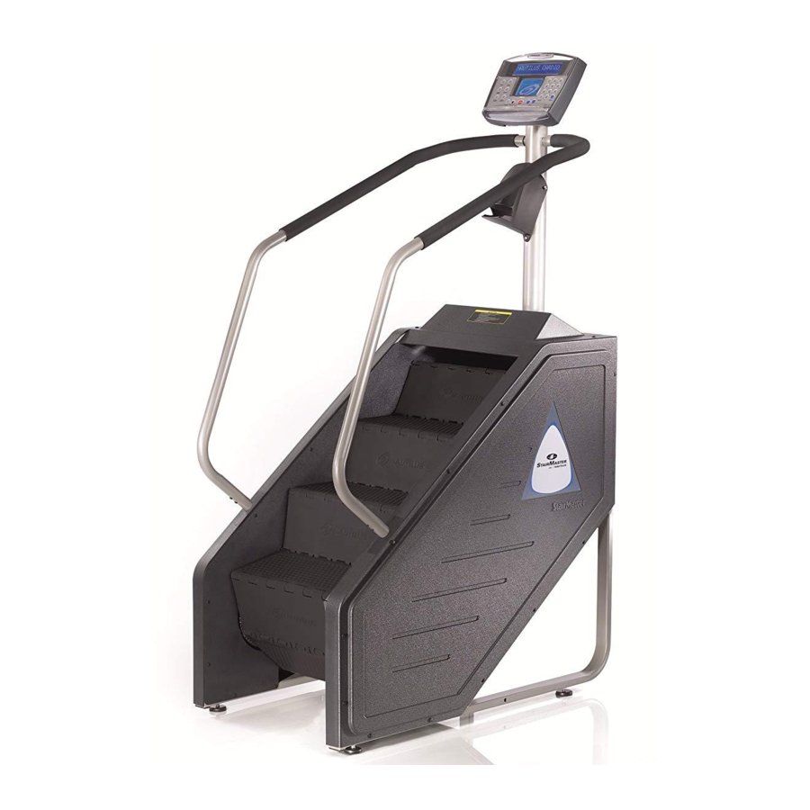
Stairmaster StepMill SM916 Assembly Manual
Stepmill
Hide thumbs
Also See for StepMill SM916:
- Assembly manual (64 pages) ,
- Owner's manual (44 pages) ,
- Wiring diagram (13 pages)

Related Manuals for Stairmaster StepMill SM916


Summary of Contents for Stairmaster StepMill SM916
-
Page 1: Assembly Manual
SM 916 StepMill ® Assembly Manual Nautilus Bowflex Schwinn Fitness StairMaster Universal Nautilus Institute ® ® ® ® ® ® 001-7199 - 052008A... -
Page 2: Table Of Contents
Table of Contents Model SM916 Specifications ............................2 Safety Warnings ................................3 Safety Caution and Warning Labels ........................4 Before You Start ................................5 Hardware ..................................6 Box Contents ..................................7 Assembly ..................................9 Contact Information ..............................15 Product Specifications Model SM 916 Dimensions: 29" W x 50" L x 81" H ( 74 cm x 127 cm x 206 cm) Unit Weight: 409 lbs ( 185.5 kg) -
Page 3: Safety Warnings
Important Safety Warnings This icon means a potentially hazardous situation which, if not avoided, could result in death or serious injury. Obey the following warnings: Read and understand all Warnings on this machine. Specific Caution, Warning and/or Danger decals may be applied to call attention to specific hazards. •... -
Page 4: Safety Caution And Warning Labels
Label 1: Power caution label. Location: Affixed to the lower front of the left side cover (see Figure 1). Figure 1 SM916 Label 2: General exercise warning label. Location: Affixed to the mast below the console (see Figure 2). MANUAL... -
Page 5: Before You Start
Before You Start SM 916 . We Locate the area where you will assemble and use your StairMaster Commercial Series StepMill ® ® recommend you install it on a hard, level surface. Allow an assembly area of at least 36” (0.91 m) on each side and behind the machine. -
Page 6: Hardware
Hardware Hardware Ref # Description 5/16 " Hex Screw 1/4 " - 20 x 1/2" Button Head Screw 1/4 " - 20 x 3/4" Phillips Head Screw 5/16 " - Flat Washer 5/16 " - 18 Nut Hardware not to scale Assembly Manual... -
Page 7: Box Contents
Qué no cubre esta garantía: SC 916 que pesen más del a elección de Nautilus, Inc. al reembolso del precio de compra del producto de 1. Usuarios de la escaladora comercial StairMaster ® ejercicios en cuestión. ESTOS RECURSOS SON LOS ÚNICOS Y EXCLUSIVOS límite de peso máximo de 300 libras (136 kg). - Page 8 Box Contents box 2 Ref # Descritpion Upper Mast Console Bottle Holder Assembly Manual...
-
Page 9: Assembly
Assembly SM 916 . All instructions in The following instructions provide direction to assemble the StairMaster StepMill ® ® the manual are given with the orientation of standing on a level surface and facing the machine. Step 1: Unpacking the StepMill® SM 916 Tools •... - Page 10 Assembly Step 3: Install Levelers and Transport Wheels Parts • Ref 11, Transport Wheels Qty. 2 • Ref 14, Levelers Qty. 4 Hardware • Ref 12, Cotter Pins Qty. 2 • Ref 13, Clevis Pins Qty. 2 Use a second person when performing assembly steps requiring heavy lifting or awkward movements.
- Page 11 Assembly Step 4: Attach Mast Parts • Mast Qty. 1 Hardware • Ref 1, 5/16" - Hex Screw Qty. 4 • Ref 4, 5/16" - Washer Qty. 4 • Ref 5, 5/16" - 18 Nut Qty. 4 4-1 Locate the two sets of cables for the console, feed the cables through the bottom of the Mast to the top and secure to the top plate.
- Page 12 Assembly Step 6: Install Top Cover Parts • Completed assembly from Step 5. • Ref 17, Top Cover Qty. 1 Hardware • Ref 11, Rivet Qty. 8 Tools • Ref 9, Rivet Puller 6-1 Remove the top Rivets and upper side Rivets on both left and right side covers to install the Top Cover (Figure 6 A).
- Page 13 Assembly Step 7: Install Console Parts • Completed assembly from Step 6. • Ref 19, Console Qty. 1 Hardware • Ref 4, 1/4" - 20 x 3/4" Phillips Head Screw Qty. 4 Tools • Phillips Head Screwdriver 7-1 Connect the cables from the Mast to the 20 pin connector on the PC board (Figure 7A &...
- Page 14 Assembly Step 8: Install Cup Holder Parts • Completed assembly from Step 7. • Ref 20, Cup Holder Qty. 1 Hardware • Ref 2, 1/4" - 20 x 1/2" Button Head Screw Qty. 3 8-1 Attach the Cup Holder to the Mast with 3 Button Head Screws (Figure 8).
- Page 15 Assembly Step 10: Connecting Power Supply Parts • Ref 15, Power Supply Qty. 1 10-1 Connect the DC Power Cable from the Power Supply to the power connector located on the bottom cover (Figure 10). 10-2 Place the Power Supply on the floor near an AC wall outlet.
- Page 16 Contacts UNITeD STATeS OFFICeS INTeRNATIONAL OFFICeS For technical assistance and a list of distributors in your e-mail: customerservice@nautilus.com area, please call or fax one of the following numbers. TECHNICAL/CUSTOMER SERVICE INTERNATIONAL CUSTOMER SERVICE Phone: 800-NAUTILUS (800-628-8458) Nautilus International S.A. Fax: (877) 686-6466 Rue Jean Prouvé...
- Page 17 © 2008 . Nautilus, Inc. All rights reserved. Nautilus, the Nautilus Logo, Bowflex, Bowflex Logo, StairMaster, StairMaster Logo, StepMill, Universal and Nautilus Institute are either registered trademarks or trademarks of Nautilus, Inc. Schwinn is a registered trademark. All other trademarks are owned by their respective companies.
Need help?
Do you have a question about the StepMill SM916 and is the answer not in the manual?
Questions and answers