Advertisement
Quick Links
INSTALLATION
INSTRUCTIONS
PARTS LIST
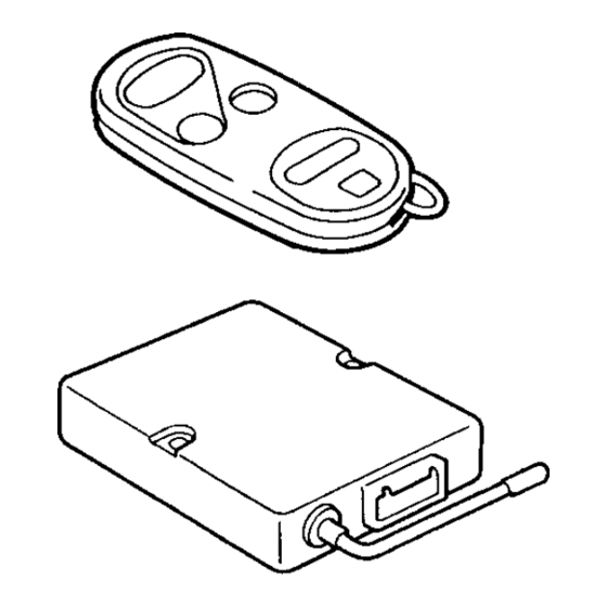
Security System (sold separately):
P/N 08E51-S84-100
2 Remote controls
Control unit
LED
Push nut
2-Pin connector (for LED)
Disarm switch
Window decal
3-Pin connector
(for disarm switch)
Nut, 12 mm
Washer
Owner's Manual
2 Washer-screws, 4 x 30 mm
© 2000 American Honda Motor Co., Inc - All Rights Reserved.
www.collegehillshonda.com/parts
Accessory
SECURITY SYSTEM
All 21624 (0008)
Y0581-A
Application
2001 ACCORD
2- AND 4-DOOR
(INCLUDES V6)
Security System Attachment (sold separately):
P/N 08E55-S84-100
Security system
wire harness
Sub-harness
White connector clip
Control unit bracket
2 Relay brackets
5 Short wire ties
3 Washer bolts, 6 x 12 mm
Ground bolt
3 Flange nuts, 6 mm
3 Self-tapping screws
Publications No.
All 21624
Issue Date
AUG 2000
1 of 12
08E55-S84-1000-91
Advertisement

Related Manuals for Honda Automobile Accessories


Summary of Contents for Honda Automobile Accessories
-
Page 1: Installation Instructions
INSTALLATION INSTRUCTIONS PARTS LIST Security System (sold separately): P/N 08E51-S84-100 2 Remote controls Control unit Push nut 2-Pin connector (for LED) Disarm switch Window decal 3-Pin connector (for disarm switch) Nut, 12 mm Washer Owner’s Manual 2 Washer-screws, 4 x 30 mm ©... -
Page 2: Tools And Supplies Required
Wire tie with clip 9 Long wire ties Cushion tape Red connector clip Relay, 4-pin Relay, 5-pin Fuse label Cover 2 of 12 TOOLS AND SUPPLIES REQUIRED Small flat-tip screwdriver #2 Phillips screwdriver Eye protection (face shield, safety goggles, etc.) Center punch Drill 5.5 mm, 10 mm, and 12 mm Drill bits... -
Page 3: Installation
Adjusting the Control Unit • Use a small flat-tip screwdriver to change the mode switch and the horn/siren switch and to adjust sensitivity. GLASS BREAKAGE SENSOR SENSITIVITY ADJUSTMENT KNOB MIN MAX Mode Switch: • Set the mode switch according to the customer’s choice. - Page 4 Remove the left fuse box cover (three retaining clips and two tabs). CLIP LEFT FUSE BOX COVER RETAINING CLIPS Remove the driver's dashboard lower cover (three screws, and five retaining clips). SCREW SCREW DRIVER'S DASHBOARD LOWER COVER CLIP 4 of 12 Remove the driver’s door sill molding (four clips).
- Page 5 Remove the right fuse box cover (three retaining clips and two tabs). RIGHT FUSE 10. Remove the passenger’s dashboard lower cover (three screws and seven retaining clips). GLOVE BOX SCREW PASSENGER'S DASHBOARD LOWER COVER © 2000 American Honda Motor Co., Inc - All Rights Reserved. 11.
- Page 6 13. Measure and mark the upper steering column cover. 5.5 mm DRILL UPPER STEERING COLUMN COVER 20 mm 14. While wearing eye protection, lightly center-punch the mark; then drill a 5.5 mm hole through the upper steering column cover. Remove all burrs. 15.
- Page 7 19. Route the terminal ends of the disarm switch through the hole you just drilled, and secure it with the washer and 12 mm nut from the kit. WASHER DISARM SWITCH 20. Locate the 3-pin connector included in the kit. Firmly push the disarm switch terminals into the 3-pin connector until they click into position, and lower the lock.
- Page 8 23. Secure the disarm switch wire harness to the disarm switch with one short wire tie, then attach the harness to the driver's dashboard lower cover with two halves of a cushion tape in the areas shown. (Cut a cushion tape in half with scissors, and use the two halves to secure the harness.) CONNECTOR CLIP...
- Page 9 28. Remove the upper bolt that fastens the engine hood opener, and attach the ground terminal of the security system wire harness with the ground bolt from the kit. 1-PIN CONNECTOR OF SECURITY SYSTEM WIRE HARNESS (WHITE) No. 5 CONNECTOR OF FUSE BOX ENGINE HOOD OPENER...
- Page 10 33. Remove the clip from the hole in the left knee bolster, use a utility knife to cut the clip off of the vehicle harness. Take care not to damage the vehicle harness. HARNESS CLIP (Cut and discard.) 34. Assemble three fuse cases as shown. Attach the appropriate fuse label to each fuse case of the security system wire harness, then attach the red connector clip as shown.
- Page 11 39. Route the 2-pin connector of the LED through the lower steering column cover, and connect it to the 2-pin connector of the security system wire harness. Reinstall the lower and upper steering column covers. UPPER STEERING COLUMN COVER SECURITY SYSTEM WIRE HARNESS 40.
- Page 12 43. Plug the 3-pin connector of the security system wire harness into the 3-pin connector of the disarm switch harness. Plug the 22-pin connector of the security system wire harness into the control unit; then reinstall the driver's dashboard lower cover. SECURITY SYSTEM WIRE HARNESS 22-PIN CONNECTOR DRIVER'S...
Need help?
Do you have a question about the Automobile Accessories and is the answer not in the manual?
Questions and answers