Advertisement
SC5010
1 Heat/1 Cool
Auto Changeover
Battery or Hardwire
Programmable Electronic Thermostat
• 7-Day, 5-2-Day or 5-1-1-Day Programmable
• Configurable
• Single Stage Heat/Cool Systems
• Single Stage Heat Pump Systems
• Large Display With Backlight
• Selectable Fahrenheit or Celsius
• Compatible with Gas, Oil, or Electric
• SimpleSet™ Field Programming
• Status Indicator Light
• Relay Outputs
(minimum voltage drop in thermostat)
• Remote Sensor Compatible
• Ideally Suited for:
– Residential (New Construction/Replacement)
– Light Commercial
Installation, Operation & Application Guide
For more information on our complete range of American-made
products – plus wiring diagrams, troubleshooting tips and more,
visit us at www.icmcontrols.com
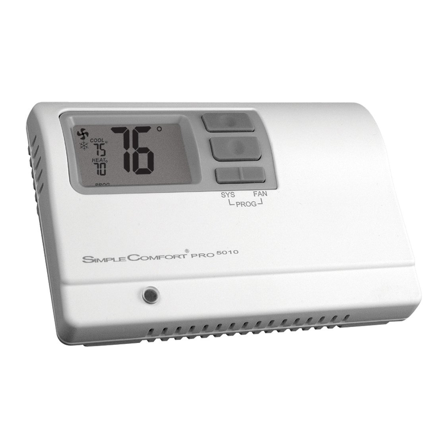
Parts Diagram
S1
S2
Y
W
G
RC
RH
C
FP
O/B
RC
RH
RESET
CONFIG
Reset switch
RC/RH Jumper
Configuration switch
Field programming pins
Icon Descriptions
Room temperature
offset activated
Fan operation icon
Lock mode activated
Cooling operation icon
Heating operation icon
Specifications
Electrical rating: • 24 VAC (18-30 VAC)
• 3.0 VDC (2 "AAA" batteries)
• 1 amp maximum per terminal
• 3 amp maximum total load
Temperature control range: 45°F to 90°F (7°C to 32°C) Accuracy: ± 1°F (± 0.5°C)
System configurations: 1-stage heat, 1-stage cool, heat pump, gas, oil, electric
Timing: Anti-short Cycle: 4 minutes
Backlight Operation: 5 seconds when configured ON
Terminations: S1, S2, Y, W/O/B, G, RC, RH, C
Important Safety Information
WARNING!: Always turn off power at the main power supply before installing, cleaning, or removing
thermostat.
• This thermostat is for 24 VAC applications only; do not use on voltages over 30 VAC
• Do not short across terminals of gas valve or system control to test operation; this will damage your thermostat
and void your warranty
• All wiring must conform to local and national electrical and building codes
• Do not use air conditioning when the outdoor temperature is below 50 degrees; this can damage your A/C system
and cause personal injuries
• Use this thermostat only as described in this manual
Package Contents/Tools Required
Package includes: SC5010 PRO thermostat on base, thermostat cover, wiring labels, screws and wall anchors, 2
"AAA" batteries, Installation, Operation and Application Guide
Tools required for installation: Drill with 3/16" bit, hammer, screwdriver
To Remove Existing Thermostat
ELECTRICAL SHOCK HAZARD – Turn off power at the main service panel by removing the fuse
or switching the appropriate circuit breaker to the OFF position before removing the existing
thermostat.
1. Turn off power to the heating and cooling system by removing the fuse or switching the appropriate circuit
breaker off.
2. Remove cover of old thermostat. This should expose the wires.
3. Label the existing wires with the enclosed wire labels before removing wires.
4. After labeling wires, remove wires from wire terminals.
5. Remove existing thermostat base from wall.
6. Refer to the following section for instructions on how to install this thermostat.
To Install Thermostat
ELECTRICAL SHOCK HAZARD – Turn off power at the main service panel by removing the fuse
or switching the appropriate circuit breaker to the OFF position before removing the existing
thermostat.
IMPORTANT: T hermostat installation must conform to local and national building and electrical codes and
ordinances.
Note: Mount the thermostat about five feet above the floor. Do not mount the thermostat on an outside wall, in
direct sunlight, behind a door, or in an area affected by a vent or duct.
1. Turn off power to the heating and cooling system by removing the fuse or switching the appropriate circuit
breaker off.
2. To remove cover, pull gently at the seam at the top.
3. Put thermostat base against the wall where you plan to mount it (Be sure wires will feed through the wire opening
in the base of the thermostat).
4. Mark the placement of the mounting holes.
5. Set thermostat base and cover away from working area.
6. Using a 3/16" drill bit, drill holes in the places you have marked for mounting.
7. Use a hammer to tap supplied anchors in mounting holes.
8. Align thermostat base with mounting holes and feed the control wires through slit in thermal intrusion barrier and
into wire opening.
9. Use supplied screws to mount thermostat base to wall.
10. Insert stripped, labeled wires in matching wire terminals.
CAUTION!: Be sure exposed portion of wires does not touch other wires.
11. Gently tug wire to be sure of proper connection. Double check that each wire is connected to the proper
terminal.
12. Insert 2 "AAA" batteries into battery holder. Orient them in the proper direction.
13. Turn on power to the system at the main service panel.
14. Configure thermostat to match the type of system you have.
15. Replace cover on thermostat by snapping it in place.
16. Test thermostat operation as described in "Testing the Thermostat".
Wiring Diagrams
Hardwired
Hardwired
4-Wire, Single Transformer
3-Wire, Single Transformer
* Common wire connection
optional with batteries
installed.
Hardwired
Hardwired
4 or 5-Wire, Single Transformer
5-Wire, Two Transformer
(Both transformers must be in phase)
Fan
Control
IMPORTANT: Before wiring, remove pre-installed
RC/RH jumper.
Hardwired – Cool or Heat Active Reversing Valve
* Common wire connection
optional with batteries
installed.
Hardwired – 4-Wire, Single Transformer
* Common wire connection
optional with batteries
installed.
Remote or Outdoor Sensor Installation (Optional)
1. Remove cover from remote sensor housing.
2. Select an appropriate location for mounting the remote sensor.
3. Mount remote sensor unit using hardware provided.
4. Install two strand shielded wire between remote sensor and thermostat. Shielded wire must be used. Do not run
remote sensor wire in conduit with other wires.
• Wire 1 should run between the S1 terminal on the
thermostat and the S1 terminal on the remote sensor
• Wire 2 should run between the S2 terminal on the
thermostat and the S2 terminal on the remote sensor
• Connect the shielding of the wire to the S2 terminal on
the thermostat
5. Configure the thermostat to operate with the remote
sensor (see Configuration Mode setting 10).
ACC-RT104
Note: Remote or outdoor sensor reading can be
Remote Sensor
(Optional)
displayed by simultaneously pressing the Down
and SYS buttons.
Installing and Changing Batteries
If your LCD is blank, or displaying LO BAT, the batteries are not installed or need to be changed. We suggest you
change the batteries at least once a year, or whenever the LO BAT warning displays.
Remove the cover, and install the two "AAA" alkaline batteries into the battery compartment. Proper battery
installation is important! Make sure the positive ends of the batteries match the positive terminals in the battery
compartment.
Batteries will provide power to maintain the clock during a power loss.
Configuration Mode
The configuration mode is used to set the SC5010 to match your heating/cooling system. The SC5010 functions
with heat pump, air conditioning, gas, oil or electric heat systems.
To configure the SC5010, perform the following steps:
1. Verify the SC5010 is in the OFF mode.
Press the SYS (left) button until off mode displays.
2. Remove the cover of the thermostat by gently pulling near one of the
corners at the top of the thermostat.
Note: Do not force open. Use a small coin or slotted screwdriver to release tabs if necessary.
3. Press the CONFIG button for 1 second while the SC5010 is in OFF mode.
CONFIG
Press the up or down button to change settings within each screen.
Up
button
Down
button
Press the right button to advance to the next screen.
Note: Pressing the left button will return you to the previous screen.
Left
button
To exit configuration mode, press the CONFIG switch for 1 second.
Configuration Mode Settings
The setup screens for Configuration Mode are as follows:
1. Temperature Scale (F or C) – Choose Fahrenheit or Celsius.
Press the up or down button to select.
Press the right button to advance to the next screen.
2. Temperature Differential (1°F to 5°F) (0.5°C to 2.5°C) – Set the number of degrees
between your "setpoint" temperature and your "turn on" temperature.
Press the up or down button to set differential value.
Press the right button to advance to the next screen.
3. Deadband (1°F - 9°F) (1°C - 5°C) – Set the minimum number of degrees between your
heat set temperature and your cool set temperature in Auto changeover mode.
Press the up or down button to set deadband value.
Press the right button to advance to the next screen.
4. System – Set for heat pump, non-heat pump, reversing valve operation and number of compressor in your
system
Reversing
Choose
System
Valve Active
HP
O
Heat Pump
HP
b
Heat
Non-Heat
Pump
Heat
Press the up or down button to select.
Press the right button to advance to the next screen.
5. Lockout (0-8°, NITE, COOL-HEAT) – Select the number of degrees set temperature
can be changed during keypad lockout or select to lockout during NITE period only.
COOL-HEAT lockout allows adjustment of the set temperatures to the maximum
heat set temperature selected in Step 6 and minimum cool set temperature selected in
Step 7.
Note: The mode cannot be changed when the thermostat is locked.
Press the up or down button to select.
Press the right button to advance to the next screen.
6. Maximum Heat Setpoint (45°F to 90°F) (7°C to 32°C)
Adjust to control the maximum heat set temperature allowed.
Press the up or down button to select.
Press the right button to advance to the next screen.
7. Minimum Cool Setpoint (45°F to 90°F) (7°C to 32°C)
Adjust to control the minimum cool set temperature allowed.
Press the up or down button to select.
Press the right button to advance to the next screen.
8. Room Temperature Offset (+9°F to -9°F) (+4.5°C to -4.5°C)
Adjust to calibrate displayed room temperature to match actual room temperature.
Note: When not set to 0, will display
Press the up or down button to select.
Press the right button to advance to the next screen.
9. Maximum Cycles Allowed Per Hour (- -, 2-6)
- - = as many as needed, 2-6 = maximum cycles/hour
Press the up or down button to select.
Press the right button to advance to the next screen.
PM
OFF
10. Temperature Sensor (1-4)
1. Only on-board sensor determines room temperature.
2. Only remote sensor determines room temperature.
3. Average temperature of on-board and remote sensor.
4. Only on-board sensor will be used until NITE period, and then only remote sensor
is used.
Press the up or down button to select.
Press the right button to advance to the next screen.
11. Cooling Fan Delay Off Time (0, 30, 60, 90 seconds)
Select the fan purge time for cooling.
Press the up or down button to select.
Right
button
Press the right button to advance to the next screen.
Number of Com-
Type of
pressors
Heat
1
1
Gas
Electric
OFF
Advertisement
Table of Contents

Related Manuals for ICM Controls SC5010


Summary of Contents for ICM Controls SC5010
- Page 1 11. Cooling Fan Delay Off Time (0, 30, 60, 90 seconds) Package Contents/Tools Required IMPORTANT: Before wiring, remove pre-installed Select the fan purge time for cooling. Press the right button to advance to the next screen. RC/RH jumper. Press the up or down button to select. Note: Pressing the left button will return you to the previous screen. Left Right Package includes: SC5010 PRO thermostat on base, thermostat cover, wiring labels, screws and wall anchors, 2 button button Press the right button to advance to the next screen. “AAA” batteries, Installation, Operation and Application Guide Tools required for installation: Drill with 3/16” bit, hammer, screwdriver To exit configuration mode, press the CONFIG switch for 1 second.
- Page 2 When the room temperature is greater than the set cool temperature (by the differential temperature), the cooling simultaneously) in for 2 seconds to return to the OFF mode. Master’s FP pins and the other end to the Target’s FP pins. device is activated and the green indicator light (configurable) on the thermostat will turn on. The SC5010 will Fan Test stop outputting and the green light will turn off when the call for cooling is satisfied. The thermostat will not let the Note: Target thermostat must be powered with 24 VAC for field programming to occur compressor come on for 4 minutes after it turns off. This protects your compressor. 1. Press FAN (right) button. Fan displays. Indoor fan turns ON. When the connection has been made correctly, the master thermostat will power Lockout Feature 2. Press FAN (right) button. Indoor fan turns OFF. The SC5010 has five possible operating modes: OFF, Heat, Cool, Heat & Cool, and Program mode. In off mode, up and the target will count from 5 down to 1. It will then display the LOCK confirming the data the thermostat will not turn on heating or cooling devices. The manual fan can be turned on in all operating modes has been saved in memory. The SC5010 has a button lockout feature so the mode cannot be changed and the using the fan button. In heat mode, the thermostat controls the heating system. In the cool mode, the thermostat When all target thermostats have been completed, reinstall the master thermostat. temperature adjustment is limited. Select the appropriate lockout from Configuration controls the cooling system. In heat & cool mode, the thermostat controls both the heating and cooling systems. In Mode Settings (Step 5) of this guide. Press the up and down buttons and the CONFIG switch simultaneously for 5 seconds to exit from the data transfer program mode, the thermostat will automatically be controlled by the set program. Program mode can function with mode and to return the master thermostat to the OFF mode.
Need help?
Do you have a question about the SC5010 and is the answer not in the manual?
Questions and answers
Temperature differential for 5010 for on/off for set temperature
The temperature differential for the ICM Controls SC5010 is adjustable. It can be configured in the thermostat's settings to control how frequently the system turns on and off at the set temperature.
This answer is automatically generated