Table of Contents
Advertisement
Programmable
Thermostats
2020
2220
1 Specifications
2 About Your Thermostat
3 Installation
4 System Testing
5 Setting User Options
Warning
Attention
Read all instructions before proceeding.
This thermostat requires 24 Volt AC Power or two (2) properly installed
"AA" Alkaline batteries for proper operation. When connecting 24 Volt
AC Power the batteries may be installed as a backup.
For use only as described in this manual. Any other use
will void warranty.
1 Specifications
This thermostat is compatible with:
• Single stage heat / cool conventional and heat pump systems
• Conventional systems up to 2 heat / 2 cool (2220 only)
• Single compressor heat pump systems with an auxiliary heat stage (2220 only)
• 250 – 750 millivolt heat only systems
Electrical and control specifications:
• Electrical Rating: 24 Volt AC
• 1 amp maximum load per terminal
• AC Power: 18 – 30 Volts AC
• DC Power: 3.0 Volt DC (2 "AA" Alkaline Batteries Included)
• Control Range: 45° – 90° F (7° – 32° C)
• Temperature Accuracy: +/- 1° F (+/- .5° C)
Terminations
• 2020 – Rc, Rh, O, B, Y1, W1, G, C
• 2220 – Rc, Rh, O, B, Y1, Y2, E/W1, G, W2, C
Single Stage Heat / Cool
Conventional and Heat Pump
Up to 2 Heat / 2 Cool Conventional
Up to 2 Heat / 1 Cool Heat Pump
Model number is located on back of thermostat
6 Setting Your Program Schedule
7 Operating Your Thermostat
8 Additional Operation Features
9 Thermostat Maintenance
Turn off power to the heating or cooling
equipment before installation.
For installation by experienced service
technicians only.
®
Detailed
User Guide
2020W-100-05
Advertisement
Table of Contents

Related Manuals for Braeburn 2020


Summary of Contents for Braeburn 2020
- Page 1 Detailed Programmable User Guide Thermostats Single Stage Heat / Cool 2020 Conventional and Heat Pump Up to 2 Heat / 2 Cool Conventional 2220 Up to 2 Heat / 1 Cool Heat Pump Model number is located on back of thermostat...
-
Page 2: About Your Thermostat
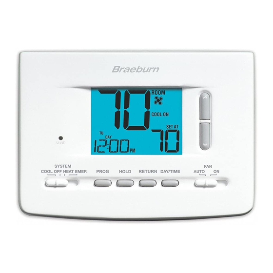
2 About Your Thermostat Room Temperature ... Displays the current room temperature Day of Week ...... D isplays the current day of week Program Event Indicator .. I ndicates the current program event Time of Day ....... Displays the current time of day Low Battery Indicator .. I ndicates when batteries need to be replaced Fan Indicator ....Indicates when the system fan is running Hold Mode Indicator .. D isplays if in HOLD mode System Status Indicator . -
Page 3: Installation
Warning Disconnect power before beginning installation. Thermostat Location Install the thermostat approximately 5 feet (1.5m) above the floor in an area that has a good amount of air circulation and maintains an average room temperature. Avoid installation in locations where the thermostat can be affected by drafts, dead air spots, hot or cold air ducts, sunlight, appliances, concealed pipes, chimneys and outside walls. Install your new Braeburn thermostat in 5 basic steps: 1 Install the Sub-Base 2 Provide Power 3 Connect Your Wires 4 Set Installer Switches 5 Attach Thermostat to Sub-Base Install the Sub-Base: • Remove the sub-base from the body of the thermostat. • Mount the sub-base as shown below: Drill 3/16” pilot holes in your desired location. -
Page 4: Connect Your Wires
Provide Power 24VAC Power Terminal (C) • For 24 Volt AC power, you must connect the common side of the trans- former to the C terminal on the thermostat sub-base. • For primary or back-up power, insert the 2 supplied “AA” type alkaline batteries into the battery compartment located in the rear housing of the thermostat. Make sure to position the Positive (+) and Negative (-) sides of the batteries correctly with the +/- symbols in the battery compartment. Connect Your Wires Wiring Terminations Terminal Function Description Rc Input 24 Volt AC Cooling Transformer (Dual Transformer Systems Only) Rh Input Power Connection (24 Volt AC Heating Transformer or Millivolt Power Source) O Output Reversing Valve (Cool Active) - Page 5 Conventional Systems Typical Wiring Configurations NOTE: The “Installer Switch” option will be configured in the next step. Heat Only or Millivolt Set Installer Switch to CONV Rh Power Connection W Heat Relay (appears as W1/E on 2220) G Fan Relay [note 4] C 24 Volt AC Transformer Common [note 1] 1 HEAT / 1 COOL Single or Dual Transformer Set Installer Switch to CONV Rh 24 Volt AC Power (heating transformer) [note 2] Rc 24 Volt AC Power (cooling transformer) [note 2]...
-
Page 6: Heat Pump Systems
Heat Pump Systems Typical Wiring Configurations NOTE: The “Installer Switch” option will be configured in the next step. 1 HEAT / 1 COOL - No Auxiliary Heat Set Installer Switch to HP 24 Volt AC Power Connected to Rh with supplied Jumper Wire O or B Changeover Valve [note 2] Compressor Relay Fan Relay 24 Volt AC Transformer Common [note 1]... -
Page 7: Attach Thermostat To Sub-Base
NOTE: Installer switches are located on the back of the thermostat. The reset button must be pressed after making any changes to these switches. Attach Thermostat to Sub-Base 1. Line up the thermostat body with the sub-base. 2. Carefully push the thermostat body against the sub-base until it snaps into place. 3. Insert quick reference card into slot on top of thermostat. 4 System Testing Warning Read Before Testing • Do not short (or jumper) across terminals on the gas valve or at the heating or cooling system control board to test the thermostat installa- tion. This could damage the thermostat and void the warranty. -
Page 8: Setting User Options
5 Setting User Options Advanced User Options User options allow you to customize some of your thermostat’s features. Most users will not need to make any changes to the settings in this section. To enter the User Options menu, hold down the RETURN button for approximately 3 seconds until the screen changes and displays the first User Option. Press the or button to change the setting for the displayed User Option. After you have made your desired setting, press RETURN to advance to the next User Option. The thermostat will return to normal mode after your last user option is made or after no keys have been pressed for 15 seconds. Table of User Options User Factory Setting... -
Page 9: Setting The Time And Day
Extended Hold Period (User Option 3) The Extended Hold Period lets you select the period your thermostat will hold the temperature when the HOLD mode is activated (See “Temperature Adjustment”). When LNG is selected the thermostat will hold your temperature indefinitely. When 24HR is selected, the thermostat will hold your temperature for 24 hours and then return to the current program at that time. Service Filter Monitor (User Option 4) The Service Filter Monitor is a user selectable service monitor that will display a reminder for a required air filter replacement by flashing the SERVICE FILTER segment in the display. When the selected interval has been reached, and required cleaning or replacement has been performed, touch the RETURN button to reset the timer and reset the service monitor. Select OFF or a set number of days before the reminder will appear. Adaptive Recovery Mode (early recovery) (User Option 5) During Adaptive Recovery Mode (ARM ), room temperature is recovered ™ gradually by turning on the heating or cooling before the end of the set back period. The set point temperature is changed to that of the upcoming program temperature. 6 Setting Your Program Schedule Setting the Time and Day 1. -
Page 10: Programming A 5-2 Day Residential Schedule
5-2 Day Programming– Weekday/Weekend Factory Settings 4 Event Time: 6:00 am Time: 6:00 am Heat: 70˚ F (21˚ C) Heat: 70˚ F (21˚ C) Cool: 75˚ F (24˚ C) Cool: 75˚ F (24˚ C) Time: 8:00 am Time: 8:00 am Heat: 62˚... -
Page 11: Operating Your Thermostat
7 Operating Your Thermostat Setting the System Control Mode The System Control has several modes of operation that can be selected by moving the SYSTEM switch to the appropriate position. COOL Only your cooling system will operate Heating and cooling systems are off HEAT Only your heating system will operate Additional Switch Position (Model 2220 Only): EMER Operates a backup heat source (Emergency Heat) for heat pump systems only NOTE: If your model 2220 was configured for a conventional system (CONV) then you will not have the EMER (emergency heat) option and “NO EMER SET”... -
Page 12: Additional Operation Features
Status Indicators Status indicators appear in the display to let you know if your system is heating, cooling or off. HEAT ON Indicates that your heating system is running. COOL ON Indicates that your cooling system is running. SERVICE Indicates that a user selectable service reminder was selected (see “Service Filter Monitor, page 8). Additional status indicators (Model 2220 Only): Indicates that the auxiliary stage of heating is running (multi-stage systems only). EMER Indicates that the emergency heating system is running (heat pump systems only). Program Event Indicators Program Event Indicators appear in the display to let you know what part of your current program is active. The 4 different program event indicators are MORN, DAY, EVE and NIGHT. When the program event indicator is flashing, your program has been temporarily bypassed and will resume at the next scheduled event. Note: You will not see a program event indicator while in HOLD Mode. Resetting the Thermostat This thermostat provides you with a reset button that will erase all of your user settings and 5-2 day programming. -
Page 13: Thermostat Maintenance
Thermostat Cleaning Never spray any liquid directly on the thermostat. Using a soft damp cloth wipe the outer body of the thermostat. Never use any abrasive cleansers to clean your thermostat. Store this manual for future reference Limited Warranty When installed by a professional contractor, this product is backed by a 5 year limited warranty. Limitations apply. For limitations, terms and conditions, you may obtain a full copy of this warranty: · Visit us online: www.braeburnonline.com/warranty YEAR · Phone us: 866.268.5599 LIMITED WARRANT Y · Write us: Braeburn Systems LLC 2215 Cornell Avenue Montgomery, IL 60538 Braeburn Systems LLC 2215 Cornell Avenue • Montgomery, IL 60538 Technical Assistance: www.braeburnonline.com Call us toll-free: 866-268-5599 (U.S.) 630-844-1968 (Outside the U.S.) 2020W-100-05 ©2013 Braeburn Systems LLC • All Rights Reserved • Made in China.
Need help?
Do you have a question about the 2020 and is the answer not in the manual?
Questions and answers
Hello, my Braeburn 2020 thermostat is showing my house to be a very low temperature, so it keeps blowing heat even though my house is hot. I have changed the batteries, reset it, and cleaned around the sensors, but nothing has worked. I have it set to off, but the heater is still blowing hot air.
If your Braeburn 2020 thermostat is blowing hot air even when set to off, possible reasons include:
1. Fan Mode Setting – If the fan switch is set to "ON," the system fan will continue running even when heating or cooling is off. Set it to "AUTO" so it only runs when heating or cooling is active.
2. System Malfunction – The thermostat may not be correctly controlling the HVAC system due to wiring issues, a stuck relay, or a malfunctioning heating system.
3. Compressor Protection Delay – The thermostat includes an automatic compressor protection delay, which may cause a short delay after turning off the system.
4. Installation Issues – Incorrect wiring or improper installation could result in the heating system staying on when it should be off.
Check the fan setting first, and if the issue persists, inspect the wiring or consult a professional.
This answer is automatically generated
@Mr. Anderson thank you so much for your help! I did have the **** setting incorrectly, so that issue was fixed. Originally, the thermostat reading was off, and then I had the issue with the ****. Now, it seems the thermostat is misreading the temperature of my house and the heater turns on even when it's warm in my house. I don't know what is going on there, but i might just have to buy a new thermostat. Thanks again for your help. It was greatly appreciated.
My braeburn thermostat defaults to 69 throughout the day. I have my program set for 24/7, but nowhere in the program has the thermostat been set for 69. Do you think it's defective?
How turn off auto time set
no display on thermostat, already changed the battery
If there is no display on the Braeburn 2020 thermostat after changing the battery, it may be due to the batteries being installed incorrectly. Ensure the new batteries are properly positioned with the correct (+) and (−) orientation.
This answer is automatically generated