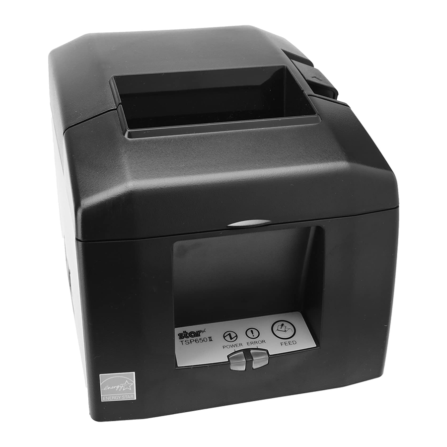
Star TSP650 Manual
Thermal printer tsp650 series
Hide thumbs
Also See for TSP650:
- Hardware manual (49 pages) ,
- Software manual (11 pages) ,
- Manual (11 pages)
Table of Contents
Advertisement
Advertisement
Table of Contents

Related Manuals for Star TSP650


Summary of Contents for Star TSP650
-
Page 1: Hardware Manual
THERMAL PRINTER TSP650 SERIES Hardware Manual... -
Page 2: Trademark Acknowledgments
Trademark acknowledgments TSP650: Star Micronics Co., Ltd. Notice • All rights reserved. Reproduction of any part of this manual in any form whatsoever, without STAR’s express permission is forbidden. • The contents of this manual are subject to change without notice. -
Page 3: Table Of Contents
TABLE OF CONTENTS 1. Unpacking and Installation ........................1 1-1. Unpacking ............................1 1-2. Choosing a place for the printer ....................2 2. Parts Identification and Nomenclature ....................3 2-1. Cutter Model ..........................3 2-2. Tear Bar Model ..........................3 3. Setup ................................4 3-1. Connecting the Cable to the PC ....................4 3-2. - Page 4 13-2. RS-232C Connector ........................46 13-3. Cable Connections ........................48 14. USB and Ethernet Interface ........................49 15. Peripheral Unit Drive Circuit ......................50 16. Memory Switch Settings ........................52 17. Release History .............................53 Please access the following URL http://www.star-m.jp/eng/dl/dl02.htm for the latest revision of the manual.
-
Page 5: Unpacking And Installation
1. Unpacking and Installation 1-1. Unpacking After unpacking the unit, check that all the necessary accessories are included in the package. Switch blind Paper roll holder Holding plate Paper roll CD-ROM Screws Rubber feet Printer Setup sheets Note Note: The ferrite core and fastener provided with your printer depend on your printer configura- tion. -
Page 6: Choosing A Place For The Printer
1-2. Choosing a place for the printer Before actually unpacking the printer, you should take a few minutes to think about where you plan to use it. Remember the following points when doing this. P Choose a firm, level surface where the printer will not be exposed to vibration. P The power outlet you plan to connect to for power should be nearby and unobstructed. -
Page 7: Parts Identification And Nomenclature
2. Parts Identification and Nomenclature 2-1. Cutter Model Cover open lever Printer cover Push this lever in the direction of the Open this cover to arrow to open the printer cover. load or replace paper. Control panel Power switch Features LED indicators to Used to turn on/off indicate printer status and power to the printer. -
Page 8: Setup
3. Setup 3-1. Connecting the Cable to the PC 3-1-1. Parallel Interface Cable Connect the parallel interface cable to a parallel port of your PC. 3-1-2. RS-232C Interface Cable Connect the RS-232C interface cable to a RS-232C port of your PC. 3-1-3. -
Page 9: Connecting The Cable To The Printer
3-2. Connecting the Cable to the Printer Note that the interface cable is not provided. Please use a cable that meets specifications. CAUTION Before connecting/disconnecting the interface cable, make sure that power to the printer and all the devices connected to the printer is turned off. Also make sure the power cable plug is disconnected from the AC outlet. 3-2-1. Parallel Interface Cable (1) Make sure the printer is turn off. (2) Affix the ferrite core onto the cable as shown in the illustration. - Page 10 3-2-2. RS-232C Interface Cable (1) Make sure the printer is turn off. CAUTION Before connecting/disconnecting the interface cable, make sure that power to the printer and all the devices connected to the printer is turned off. Also make sure the power cable plug is disconnected from the AC outlet. (2) Connect the interface cable to the connector on the rear panel of the printer. (3) Tighten the connector screws. RS-232C interface cable 3-2-3. USB Interface Cable 4 cm (maximum) Affix the ferrite core onto the USB cable as shown in the illustration below and make sure to pass the cable...
- Page 11 3-2-4. Connecting Ethernet Cable If a ferrite core is included, install the ferrite core onto the Ethernet cable according to the fol- lowing procedure to prevent electrical noise. If a ferrite core is not included, perform steps (1) and (5) only. When using an Ethernet cable that is 10 m or less, shielded cable is recommended.
-
Page 12: Installing The Printer Software
3-3. Installing the Printer Software Here is the procedure for installing the printer driver and utility software, which are stored on the supplied CD-ROM. The procedure applies to the Windows operating systems shown below. • Windows XP (SP2 or later) • Windows Vista • Windows 7 (1) Turn ON the power to your PC to start Windows. -
Page 13: Connecting The Optional Ac Adapter
3-4. Connecting the Optional AC Adapter Note: Before connecting/disconnecting the AC adapter, make sure that power to the printer and all the devices connected to the printer is turned off. Also make sure the power cable plug is disconnected from the AC outlet. (1) Connect the AC adapter to the power cable. Note: Use only the standard AC adapter and power cable. -
Page 14: Turning Power On
3-5. Turning Power On Make sure that the Power cord has been connected as described in 3-4. Turn ON the power switch located on the front of the printer. The POWER lamp on the control panel will light up. Power switch CAUTION We recommend that you unplug the printer from the power outlet whenever you do not plan to use it for long periods. -
Page 15: Connecting To A Peripheral Unit
3-6. Connecting to a Peripheral Unit You can connect a peripheral unit to the printer using a modular plug. See “Modular plug” on page 50 for details about the type of modular plug that is required. Note that this printer does not come with a modular plug or wire, so it is up to you to obtain one that suits your needs. CAUTION Make sure that the printer is turned off and unplugged from the AC outlet and that the computer is turned off before making connections. -
Page 16: Loading The Paper Roll
3-7. Loading the Paper Roll 3-7-1. Using 79.5 mm Width Paper Roll Be sure to use roll paper that matches the printer’s specification. When using a paper roll with an 57.5 mm width, install the paper roll holder as described on the following page. Cover open lever 1) Push the cover open lever, and open the printer cover. - Page 17 3-7-2. Using 57.5 mm Width Paper Roll When using a paper roll with 57.5 mm width, install the supplied paper guide on the printer. To change the effective print width (roll paper width), change the setting at memory switch configuration Utility. For details on the setting of the memory switches, refer to the software manual located in the “Documents”...
- Page 18 Caution Symbol These labels are located near the thermal print head. Because the thermal print head is hot immediately after printing, do not touch it. Static electricity can damage the thermal print head. To protect the thermal print head from static electricity, do not touch it. This symbol is placed near the cutter.
- Page 19 9) A printed piece of thermal paper may become electrically charged. If the printer is placed vertically or mounted on a wall, the cut piece of paper may stick to the printer, instead of falling. Beware that this could cause a problem if you use a stacker that stores the pieces of paper that fall freely.
-
Page 20: Attaching The Accessories
Precautions regarding installation CAUTION This caution indicates information that, if ignored, could lead to personal injury or property damage. • Be sure to have qualified personnel install the specified screws and printer to the wall. Star is not responsible for any accidents or injuries that occur as a result of improper installation, misuse, or modifications. Especially when installing the printer at a high location, make sure that the printer is securely installed to the wall. If the printer is not installed securely and falls, personal injury or damage to the printer may result. -
Page 21: Attaching The Rubber Feet
(1) Attach the holding plate to the printer. Then tighten the two screws that were supplied to secure it in place. (2) Position the printer over the screws, etc., on the wall and then slide it downward to set it in place. After setting the printer in place, check 2 3mm the screws on the wall again to make sure... -
Page 22: Switch Cover Installation
(2) Push the cover open lever, and open the printer cover. (3) Insert the roll paper as shown. 4-3. Switch Cover Installation It is not necessary to install the switch cover. Only install it if it is necessary for you. By installing the switch cover, the following become possible. -
Page 23: Consumable Parts And Ac Adapter
When consumable parts have run out, use those specified in the table below. Note: Access the following URL for the information of the recommended paper. http://www.star-m.jp/eng/dl/dl02.htm Make sure that the AC adapter specified in the table is used. Use of consumable parts or AC adapter which are not specified in the table may result in damage to the printer, fire or electric shock. -
Page 24: Ac Adapter (Option)
Note: 1) Depending on the type and thickness of the paper, it may be necessary to change the settings for printing darkness. To change the darkness settings, use the printing dark- ness settings command <ESC><RS> ‘d’ n or the memory switch. Please consult the dealer for details. -
Page 25: Control Panel And Other Functions
6. Control Panel and Other Functions 6-1. Control Panel 1 POWER lamp (Green LED) Lights when the power is ON. TSP650 POWER ERROR FEED 2 ERROR lamp (Red LED) Indicates various errors in combination with POWER lamp. 3 FEED button 3 FEED button... - Page 26 2) Non-recoverable errors Error Description POWER Lamp ERROR Recovery Conditions Lamp Flash access error Flashes at 0.5- This is not a recoverable error. second intervals EEPROM error Flashes at 0.75- This is not a recoverable error. second intervals SRAM error Flashes at 1-sec- This is not a recoverable error.
-
Page 27: Self-Printing
6-3. Self-Printing 6-3-1. Test Printing Place the thermal paper roll on the printer. Turn the power ON while holding the FEED button depressed. The printer will run a test print according to the Ver. No., DIP switch settings, and memory switch settings, etc. 6-3-2. -
Page 28: Adjusting The Near-End Sensor
7. Adjusting the Near-end Sensor Use the following procedure to adjust the near-end sensor so it is compatible with the size of paper roll you are using. 1 Open the printer cover. 2 Determine the diameter of the paper roll you are using and find the required setting in the table below. - Page 29 Adjustment value according to the paper you are using Paper Width Horizontal (standard) Layout Vertical Layout or Wall-Mount (μm) ø12 (A) inner diameter / ø18 (B) outer di- ø12 (A) inner diameter / ø18 (B) outer di- ameter core roll paper ameter core roll paper Detected diameter Remaining paper...
-
Page 30: Preventing And Clearing Paper Jams
8. Preventing and Clearing Paper Jams 8-1. Preventing Paper Jams The paper should not be touched during ejection and before it is cut. Pressing or pulling the paper during ejection may cause a paper jam, paper cutting failure or line feed failure. 8-2. Removing Paper Jam If a paper jam occurs, clear it as described below. -
Page 31: Releasing A Locked Cutter (Auto Cutter Mode Only)
8-3. Releasing a Locked Cutter (Auto Cutter Mode only) If the auto cutter locks up, set the power switch to OFF to turn off the printer, and then set the power switch to ON to turn the printer back on. A typical locked cutter will be restored when you restart the printer. -
Page 32: Periodical Cleaning
9. Periodical Cleaning Printed characters may become partially unclear due to accumulated paper dust and dirt. To prevent such a problem, paper dust collected in the paper holder and paper transport section and on the surface of the thermal head must be removed periodically. Such cleaning is recommended to be carried out once six month or one million lines. -
Page 33: Specifications
10. Specifications 10-1. General Specifications (1) Printing method Direct line thermal printing (2) Print speed Max. 1200 dots/sec. (150 mm/sec.) (3) Dot density 203 dpi: 8 dots/mm (0.125 mm/dot) (4) Printing width Max. 72 mm (5) Number of print columns 48 (12 × 24 dots) (6) Paper feed method Friction feed (7) Paper roll... -
Page 34: Auto Cutter Specifications
10-2. Auto Cutter Specifications (1) Cutting Modes Partial cut (leaves one uncut portion in center of paper) (2) Cutting Duty Min. 3 seconds/cut (3) Thickness of paper 0.065 ~ 0.085 mm 10-3. Interface RS-232C serial interface / Two-way parallel interface (IEEE1284) 10-4. Electrical Characteristics (AC adapter) (1) Input: 100 to 240 V AC, 50/60 Hz... -
Page 35: Environmental Requirements
10-5. Environmental Requirements (1) Operating Temperature 5°C to 45°C Humidity 10% to 90% RH (without condensation) (%RH) 34°C90% RH 40°C65% RH 45°C50% RH Operating environment range Temperature (°C) Operating temperature and humidity range (2) Transport/storage (except for paper) Temperature -20°C to 60°C Humidity 10% to 90% RH (without condensation) * However, the combination of 40°C and 90% RH (no condensation) is considered the worst... -
Page 36: Reliability Specifications
10-6. Reliability Specifications 1) Life Mechanical: 20 million lines Head: 100 million pulses, 100 km (±15% max. average head resistance fluctuation) For 2-color printing, 50 million pulses, 50 km (±15% max. aver- age head resistance fluctuation) Auto cutter: 1 million cuttings (provided the paper thickness is between 65 and 85 µm) <Conditions>... -
Page 37: Dip Switch Setting
11. Dip Switch Setting Two DIP switches are provided at the bottom of the printer, and can be set as given in the table below. Be sure to set the power switch to off before changing the settings. It is recommended to use a pointed item like a pen or flat-blade driver screw to change the settings. -
Page 38: Parallel Interface Model
(such as when the cover is opened, paper runs out, or an error occurs). For information about automatic status information transmission, refer to the separate Program- mer's Manual (Star Line Mode and ESC/POS Mode). – 34 –... - Page 39 *2 NSB Function When this function is enabled, status information is sent automatically whenever the printer enters into reverse forwarding mode. For information about automatic status information transmission, refer to the separate Program- mer's Manual (Star Line Mode). DIP-SW 2 Switch Function...
-
Page 40: Rs-232C Interface Model
(such as when the cover is opened, paper runs out, or an error occurs). For information about automatic status information transmission, refer to the separate Program- mer's Manual (Star Line Mode and ESC/POS Mode). – 36 –... - Page 41 DIP-SW 2 Switch Function Always ON Should be set to on The factory settings of DIP switch are all on. – 37 –...
- Page 42 The following is the procedure for changing the settings on DIP switch No. 3. Turn off the printer and all components connected to it. Remove the 2 screws. Remove the serial interface board unit. Change the setting of the DIP switches. Replace the serial interface board unit.
-
Page 43: Usb Interface Model
DIP-SW 2 DIP-SW 1 Switch 1-1 Command emulation Star Mode ESC/POS Mode The factory settings of DIP switch are all on. The functions of switches 1-2 through 1-8 will change according to the command emulation that has been set using switche 1-1. - Page 44 (such as when the cover is opened, paper runs out, or an error occurs). For information about automatic status information transmission, refer to the separate Program- mer's Manual (Star Line Mode and ESC/POS Mode). DIP-SW 2 Switch...
-
Page 45: Ethernetinterface Model
DIP-SW 2 DIP-SW 1 Switch 1-1 Command emulation Star Mode ESC/POS Mode The factory settings of DIP switch are all on. The functions of switches 1-2 through 1-8 will change according to the command emulation that has been set using switche 1-1. - Page 46 (such as when the cover is opened, paper runs out, or an error occurs). For information about automatic status information transmission, refer to the separate Program- mer's Manual (Star Line Mode and ESC/POS Mode). DIP-SW 2 Switch...
- Page 47 Initializing Settings ■ Set the push switch as described below to initialize the setting information. Push the switch for one to five seconds while running under normal operating mode. The green and red LEDs will flash with a regular pattern. After that, push the switch once again in that state to turn OFF both of the red and green LEDs.
-
Page 48: Parallel Interface
12. Parallel Interface The two-way parallel interface is compatible with the IEEE1284 compatibility mode and nibble mode. Contact your dealer for details. Table of Connection Signals for Each Mode Compatibility Mode Nibble Mode Pin No. Direction Signal Name Signal Name nStrobe Host Clock In/Out Data0 Data0 In/Out Data1 Data1 In/Out Data2 Data2 In/Out Data3... -
Page 49: Rs-232C Serial Interface
13. RS-232C Serial Interface 13-1. Interface Specifications 1 Data transmission method: Asynchronous serial interface 2 Baud rate: Selectable from 4800, 9600, 19200, 38400 bps (Refer to “11. DIP Switch Setting”.) 3 Word length Start bit: 1 bit Data bit: 7 or 8 bits (selectable.) Parity bit: Odd, even or none (selectable.) Stop bit: 1 bit length 4 Signal polarity... -
Page 50: Rs-232C Connector
F-GND — Frame ground Transmission data Receive data Always SPACE Not used. 1) STAR Mode Not used. 2) ESC/POS Mode When DIP Switch 3-7 = OFF; A) DTR/DSR communication mode Indicates whether data receive from host is enabled or disabled. Space: Receive enabled... - Page 51 Signal Pin No. Direction Function name 2) ESC/POS Mode A) DTR/DSR communication mode Indicates whether data receive from host is enabled or disabled. Space: Receive enabled Mark: Receive disabled The busy condition can be changed by using Memory switch as follows: Memory SW Printer status 1.
-
Page 52: Cable Connections
13-3. Cable Connections The followings are a recommended interface cable connections. Printer side Host side 25 pin 9 pin INIT Note: Use shielded wire less than 3 m in length. – 48 –... -
Page 53: Usb And Ethernet Interface
14. USB and Ethernet Interface 14-1. USB Interface Specifications General Specification: Conforms to USB 2.0 Specifications Communication Speed: USB Full Speed Mode (12 Mbps) Communication Method: USB Bulk Transmission Mode Power Specifications: USB Self-power Function Connector: USB Up-Stream Port Connector (USB Type-B) 14-2. -
Page 54: Peripheral Unit Drive Circuit
15. Peripheral Unit Drive Circuit Peripheral unit drive circuit connector only connects to peripheral units such as cash drawers, etc. Do not connect it to a telephone. Use cables which meet the following specifications. Peripheral Drive Connector Modular plug Pin Signal Function I/O... - Page 55 Reference 2SD 1866 Circuit Configuration R3 = 3.5 kΩ Drive Output: 24 V, Max. 1.0 A R4 = 300 Ω TR1, TR2: Transistor 2SD 1866 or equivalent R1=10 kW R2=33 kW Notes: 1. Peripheral units 1 and 2 cannot be driven simultaneously. To drive them continuously, set the duty cycle ratio to 20% or less (excluding an externally connected buzzer).
-
Page 56: Memory Switch Settings
16. Memory Switch Settings Each memory switch is stored in EEPROM. For details on the functions and settings of memory switches, please consult the dealer. The table below shows the factory settings for the memory switches. Hexadecimal Memory Switch Code 0000 0000 0000 0000... -
Page 57: Release History
17. Release History Date Rev. No. Contents (Month/Day/ Year) Rev.1.0 09/30/2007 New Release Rev.1.2 07/30/2010 Page 6: Added the description about the Ethernet interface board IFBD-HE07. Rev.1.21 09/30/2010 Page 8: Added the description about Windows 7. – 53 –... -
Page 58: Please Access The Following Url
1150 King Georges Post Road, Edison, NJ 08837-3729 U.S.A. Tel: (int+1)-732-623-5555, Fax: (int+1)-732-623-5590 STAR MICRONICS EUROPE LTD. SPECIAL PRODUCTS DIVISION Star House, Peregrine Business Park, Gomm Road, STAR MICRONICS CO., LTD. High Wycombe, Bucks, HP13 7DL, U.K. 536 Nanatsushinya, Shimizu-ku, Shizuoka,...
Need help?
Do you have a question about the TSP650 and is the answer not in the manual?
Questions and answers