Table of Contents
Advertisement
DIGITAL CAMERA
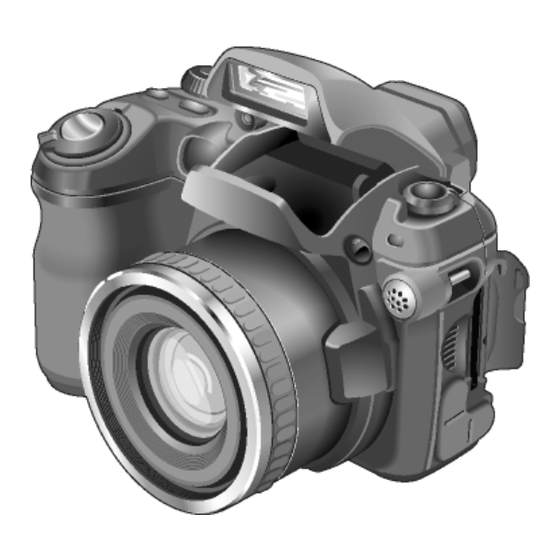
FinePix S5000
SERVICE MANUAL
US/EU/EG/CA/GE/AS-Model
WARNING
THE COMPORNENTS IDENTIFIED BY THE MARK "
" ON THE SCHEMATHIC
DIAGRAM AND IN THE PARTS LIST ARE CRITICAL FOR SAFETY.
PLEASE REPLACE ONLY BY THE COMPONENTS SPECIFIED ON THE SCHEMATHIC
DIAGRAM AND IN THE PARTS LIST.
IF YOU USE WITH PART NUMBER UN-SPECIFIED, IT MAY RESULT IN A FIRE AND AN
ELECTORICAL SHOCK.
Ref.No.:ZM00509-100
FUJI PHOTO FILM CO.,LTD.
Printed in Japan 2003.07(S.S.)
Advertisement
Table of Contents

Related Manuals for FujiFilm FinePixS5000


Summary of Contents for FujiFilm FinePixS5000
-
Page 1: Digital Camera
DIGITAL CAMERA FinePix S5000 SERVICE MANUAL US/EU/EG/CA/GE/AS-Model WARNING THE COMPORNENTS IDENTIFIED BY THE MARK “ ” ON THE SCHEMATHIC DIAGRAM AND IN THE PARTS LIST ARE CRITICAL FOR SAFETY. PLEASE REPLACE ONLY BY THE COMPONENTS SPECIFIED ON THE SCHEMATHIC DIAGRAM AND IN THE PARTS LIST. IF YOU USE WITH PART NUMBER UN-SPECIFIED, IT MAY RESULT IN A FIRE AND AN ELECTORICAL SHOCK. - Page 2 FinePix S5000 Service Manual SAFETY CHECK-OUT After correcting the original problem, perform the following safety check before return the product to the costomer. 1. Check the area of your repair for unsoldered or poorly 6. Make leakage - current measurements to determine sol dered connections.
-
Page 3: Table Of Contents
FinePix S5000 Service Manual TABLE OF CONTENTS 1.General ........4 4. Adjustments......36 1-1. Product specification ........... 4 4-1. Adjustment Procedure of Parts Replacement ..36 1-2.Names of External Components ......7 4-2. Measuring Devices ..........36 4-3. Jigs ..............36 2. -
Page 4: General
1.General FinePix S5000 Service Manual 1.General 1-1. Product specification System Model Digital camera FinePix S5000 Number of effective pixels 3.1 million pixels CCD sensor 1/2.7 inch Super CCD HR in an interwoven pattern Number of total pixels 3.14 million pixels Still image : 2816 ×... - Page 5 DPC-16 (16 MB)/DPC-32 (32 MB)/DPC-64 (64 MB)/DPC-128 (128 MB)/ DPC-256 (256 MB)/DPC-512 (512 MB) ! Fujifilm Rechargeable Battery 2HR-3UF (2×) ! Fujifilm Battery charger with Battery BK-NH/BK-NH2 (With Euro type or UK type plug) ! AC Power Adapter AC-5VH/AC-5VHS ! Carrying Case SC-FXS5 ! Image Memory Card Reader DPC-R1 •...
- Page 6 1.General FinePix S5000 Service Manual Explanation of Terms AF/AE Lock : On the FinePix S5000, pressing the shutter button down half way locks the focus and exposure settings (AF and AE lock). If you want to focus on a subject that is not centered in the frame or change the picture composition after the exposure is set, you can obtain good results by changing the composition after the AF and AE set- tings are locked.
-
Page 7: 1-2.Names Of External Components
1.General FinePix S5000 Service Manual 1-2.Names of External Components Shutter button Power switch Focus mode selector lock switch Continuous shooting button Exposure compen- sation button Focus mode selector button Mode dial W (Wide zoom) button Viewfinder T (Tele zoom) button Diopter adjustment dial EVF/LCD... - Page 8 2. Disassembly FinePix S5000 Service Manual Flash Flash pop-up button Flash control sensor Self-timer lamp Microphone AF-Assist Strap mount Illuminator Slot cover xD-Picture Card slot Lens Speaker USB socket (Mini-B) DC IN 5V (power input) socket A/V OUT (Audio visual output) socket...
-
Page 9: Disassembly
2. Disassembly FinePix S5000 Service Manual 2. Disassembly 2-1. Internal Components CABINET REAR ASSY MSW PWB ASSY KSW PWB ASSY EVF UNIT CONST LCD UNIT FLASH UNIT RSW PWB ASSY BATTERY HOLDER ASSY LCD FRAME MAIN PWB ASSY AF FRAME ASSY DCST PWB ASSY MAIN FRAME LENS UNIT... -
Page 10: Removing The R Cabinet Assy
2. Disassembly FinePix S5000 Service Manual 2-2. Removing the R CABINET ASSY [Disassembly] 1. Remove the three screws(M1.7x3.5). 2. Remove the two screws(M1.7x5). 3. Open the battery cover. 4. Raise the R CABINET ASSY in the direction of the arrow. 5. -
Page 11: Removing The Lcd Unit
2. Disassembly FinePix S5000 Service Manual 2-3. Removing the LCD UNIT [Disassembly] 1. Remove the two screws(M1.7x2.5). 2. Remove the connector. 3. Raise the LCD UNIT in the direction of the arrow. [Assembly] Assemble in the reverse order to disassembly. -
Page 12: Removing The Evf Unit
2. Disassembly FinePix S5000 Service Manual 2-4. Removing the EVF UNIT [Disassembly] 1. Remove the connector. 2. Raise the EVF UNIT in the direction of the arrow. 3. Remove the FFC [Assembly] Assemble in the reverse order to disassembly. 2-5. Removing the MAIN PWB ASSY [Disassembly] 1. -
Page 13: Removing The Battery Holder Assy
2. Disassembly FinePix S5000 Service Manual 2-6. Removing the BATTERY HOLDER ASSY [Disassembly] 1. Remove the connector. 2. Remove the screw(M1.7x8.0 ). 3. Remove the BATTERY HOLDER ASSY in the direction of the arrow. [Assembly] Set the switch lever to the off position when assembling. Note: Always ensure that the FLASH ASSY main condenser is discharged before beginning disassembly. -
Page 14: Removing The Dcst Pwb Assy
2. Disassembly FinePix S5000 Service Manual 2-7. Removing the DCST PWB Assy [Disassembly] 1. Remove the two screws(M1.7x2.5 ). 2. Remove the FFC. 3. Remove the two connectors. 4. Remove the DCST PWB Assy in the direction of the arrow. [Assembly] Put the substrate aside in the direction of the arrow when assembling. -
Page 15: Removing The Strobe Const
2. Disassembly FinePix S5000 Service Manual 2-9. Removing the STROBE CONST [Disassembly] 1. Remove the ST-BUTTON. 2. Remove the screw(M1.7x5.5). 3. Remove the connector. 2. Remove in the STROBE CONST direction of the arrow [Assembly] Make read-wire a style as shown in the figure below. Assemble in the reverse order to disassembly. -
Page 16: Schematics
3. Schematics FinePix S5000 Service Manual 3. Schematics 3-1. Cautions <Cautions when replacing parts> • Do not reuse removed parts. Always use new parts. • Note that the -ve side of tantalum condensers is readily damaged by heat. • Except for chemical condensers and tantalum condensers, voltage is not displayed on condensers with a voltage resistance of 50V or less. -
Page 17: Functions Of Primary Blocks
3. Schematics FinePix S5000 Service Manual 3-3. Functions of Primary Blocks. 3-3-1. Technical Outline The FinePix S5000 incorporates a 1/2.7 inch Fourth Generation Super CCD HR sensor with 3.1 million effective pixels and a new signal processing LSI (UCS2, IC206). The signal processing LSI (UCS2, IC206) is equivalent to the image signal processing IC (UCS, IC204, CSP) incorporated in the previous FinePix F601, however the new IC permits a dramatic reduction in the interval between photography and playback. -
Page 18: Block Diagram
3. Schematics FinePix S5000 Service Manual 3-4. Block Diagram Zoom position Zoom Focus O.LPF STRB_SY IST,GS1,GS2,END,S/S,CP Peripheral BUS 96MHz DR_SW... -
Page 19: Overall Connection Diagram
3. Schematics FinePix S5000 Service Manual 3-5. Overall connection Diagram LENS UNIT CCD_FPC MOTOR_FPC D_3.3V 1 1 D_3.3V GND 2 2 GND D_3.3V 3 3 D_3.3V FB1S029J12 GND 4 4 GND FH12_20S_0.5SH D_3.3V 5 5 D_3.3V CAM Block MOTOR Block CAM_3.3V 6 6 CAM_3.3V D_1.5V 7... -
Page 20: Ccd Block Schematic Diagram
3. Schematics FinePix S5000 Service Manual 3-6. CCD BLOCK Schematic Diagram... -
Page 21: Camera Block Schematic Diagram
3. Schematics FinePix S5000 Service Manual 3-7. CAMERA BLOCK Schematic Diagram... -
Page 22: Process Block Schematic Diagram
3. Schematics FinePix S5000 Service Manual 3-8. PROCESS BLOCK Schematic Diagram... -
Page 23: Power Block Schematic Diagram
3. Schematics FinePix S5000 Service Manual 3-9. POWER BLOCK Schematic Diagram... -
Page 24: Lcd-Evf Block Schematic Diagram
3. Schematics FinePix S5000 Service Manual 3-10. LCD-EVF BLOCK Schematic Diagram... -
Page 25: F Sw Block Schematic Diagram
3. Schematics FinePix S5000 Service Manual 3-11. F SW BLOCK Schematic Diagram 3-12. M SW BLOCK Schematic Diagram... -
Page 26: Key Sw Block Schematic Diagram
3. Schematics FinePix S5000 Service Manual 3-13. KEY SW BLOCK Schematic Diagram... -
Page 27: Motor Block Schematic Diagram
3. Schematics FinePix S5000 Service Manual 3-14. MOTOR BLOCK Schematic Diagram... -
Page 28: Power On Block Schematic Diagram
3. Schematics FinePix S5000 Service Manual 3-15. POWER ON BLOCK Schematic Diagram... -
Page 29: Flash Block Schematic Diagram
3. Schematics FinePix S5000 Service Manual 3-16. FLASH BLOCK Schematic Diagram... -
Page 30: R Sw Block Schematic Diagram
3. Schematics FinePix S5000 Service Manual 3-17. R SW BLOCK Schematic Diagram... -
Page 31: Ccd Fpc Assy Component Locations
3. Schematics FinePix S5000 Service Manual 3-18. CCD FPC ASSY Component Locations <Side A> <Side B> 3-19. RSW PWB ASSY Component Locations <Side A> <Side B>... -
Page 32: Main Pwb Assy Component Locations
3. Schematics FinePix S5000 Service Manual 3-20. MAIN PWB ASSY Component Locations <Side A> <Side B>... -
Page 33: Dcst Pwb Assy Component Locations
3. Schematics FinePix S5000 Service Manual 3-21. DCST PWB ASSY Component Locations <Side A> <Side B>... -
Page 34: Ksw Pwb Assy Component Locations
3. Schematics FinePix S5000 Service Manual 3-22. KSW PWB ASSY Component Locations <Side A> <Side B>... -
Page 35: Msw Pwb Assy Component Locations
3. Schematics FinePix S5000 Service Manual 3-23. MSW PWB ASSY Component Locations <Side A> <Side B>... -
Page 36: Adjustments
4. Adjustments FinePix S5000 Service Manual 4. Adjustments 4-1. Adjustment Procedure of Parts Replacement Adjust in the order noted below after replacing the parts in the table. CCD data CAMERA Battery Flash VIDEO End setting AF ASIST LIGHT LENS ASSY MAIN PWB ASSY DCST PWB ASSY FLASH UNIT... -
Page 37: Jig Connections
4. Adjustments FinePix S5000 Service Manual 4-4. Jig Connections USB CABLE To PCI-2746C Board AC-100-240V VIDEO ADJ. JIG TV MONITOR POWER CABLE JIG * Always measure input voltage close to the DC_IN pin when making adjustments. 4-5. Environment Setup (1)Setup for camera adjustment (Fig.A) <<All white pattern>>... - Page 38 4. Adjustments FinePix S5000 Service Manual (2)Setup for AF adjustment (Fig.B) AF chart 1. Set the distance between the conversion lens and the tip of the lens to 900mm±2mm. Fluorescent light stand 2. Use a light source to illuminate the AF chart. Ensure that the luminance of the surface of the AF chart is between 9.0Ev and 12.0Ev.
-
Page 39: Installing The Jig Drivers On The Pc
4. Adjustments FinePix S5000 Service Manual 4-6. Installing the Jig Drivers on the PC * As this device uses a USB interface for communica- tions with the PC, the [USB Jig Driver] must first be installed on the PC before the PC adjustment software can be run. - Page 40 4. Adjustments FinePix S5000 Service Manual <Step 1> Double-click on the [FFW.exe] file (Fig.E) in the adjustment software folder to display the [FFW Start-up Screen] (Fig.F). <Step 2> Click on [Setting] (Fig.G-1) on the [menu bar] on the screen. Select [Mode setting] (Fig.G-2) from the pull-down menu.
-
Page 41: The Camera
4. Adjustments FinePix S5000 Service Manual Cautions for Adjustment Menu Command Details Operation Start Start program. [Caution 1] Stop Stop program. Running End setting returns the camera Pause Pause program. to the [Product mode] from the [Jig Step 0 Do not use. Terminate Terminate program. -
Page 42: Starting The Adjustment Software
4. Adjustments FinePix S5000 Service Manual 4-9. Starting the Adjustment Software <Step 1> Double-click on [FFW.EXE] in the folder copied to the C drive to display the adjustment software start-up screen [Fig.1]. Run the adjustment in accordance with the instructions on the screen. Fig.1 --->... - Page 43 Run the adjustment in 4. Adjustments FinePix S5000 Service Manual Fig.3 --->The [Jig Mode Setup Procedure Screen (Fig.3)] appears. <Step 4> Set the camera in the Jig mode, and press the Enter key. Fig.4 ---> The [Firmware Display Screen (Fig.4)] appears. (Firmware Confirmation Screen) <Step 5>...
- Page 44 4. Adjustments FinePix S5000 Service Manual Fig.5 ---> The [Adjustment Items Select Screen (Fig.5)] appears. * Adjustment Items Adjustment items Selection AF-Asasist light adjustment Press the [F 9] key. CCD data input Press the [F 4] key. Camera adjustment Press the [F 5] key. AF adjustment Press the [F 6] key.
-
Page 45: F9] : Af-Assist Light Adjustment
4. Adjustments FinePix S5000 Service Manual 4-10. [F9] : AF-Assist Light Adjustment Line chart Fluorescent light stand AF-Assist light Adjustment is required when the AF FRAME ASSY is removed. Center (1)Preparation for AF-Assist Light adjustment 1. Output the image to TV with a camera that works normally. - Page 46 4. Adjustments FinePix S5000 Service Manual <Step 1> Select [F9] from the [Adjustment Items Select Screen (Fig.5)]. (press [F9] on the PC keyboard) ---> The [AF-Assist light adjustment Preparation Screen (Fig.6)] appears. Fig.6 <Step 2> When preparations are complete, press the Enter key.
- Page 47 4. Adjustments FinePix S5000 Service Manual ---> The [AF-Assist light adjustment Screen (Fig.8)] appears. Fig.8 Adjust the adjustment screw in the camera so that the irradiation standard of the AF-assist light may enter in a specified area. <Step 4> When preparations are complete, press the Enter key. --->...
-
Page 48: F4] : Ccd Data Input
30220286 30220287 <Step 2> 30220288 3043.zip Download the ZIP file of top four digits from Web server (http://fujifilm-di.intranets.com/). 30220310 Open [ZJ00666-100(Fig.10-2-(1)] in the CCD defect data folder, and download "3022.zip[Fig.10-2-(2)]". < Fig. Q> Defect data making procedure chart Fig.10-2 <Step 3>... - Page 49 4. Adjustments FinePix S5000 Service Manual <Step 6> Select [F4] from the [Adjustment Items Select Screen (Fig.5)]. (press [F4] on the PC keyboard) ---> The [CCD Data Input Start Screen (Fig.11)] appears. <Step 7> Make the following preparations in accordance with the instructions on the [CCD Data input Start Screen (Fig.11)].
-
Page 50: F5] : Camera Adjustment
4. Adjustments FinePix S5000 Service Manual 4-12. [F5] : Camera adjustment (shutter adjustment/aperture sensitivity reduction rate adjustment/ISO sensitivity adjustment/white balance adjustment/ AE shading adjustment/offset level adjustment) Run the adjustment in accordance with the instructions on the screen. <Step 1> Select [F5] from the [Adjustment Items Select Screen (Fig.5)]. (press [F5] on the PC keyboard) Fig.13 --->... - Page 51 4. Adjustments FinePix S5000 Service Manual <Step 3> Fit the LB140 filter in accordance with the instructions on the screen (Fig.15). When preparations are complete, press the Enter key. Fig.15 ---> Camera adjustment moves to the next stage. <Step 4> Remove the LB140 filter in accordance with the instructions on the screen (Fig.16).
- Page 52 4. Adjustments FinePix S5000 Service Manual <Step 5> The screen in Fig.17 appears when adjustment is completed satisfactorily. Press the Enter key. Fig.17 ---> The system returns to the [Adjustment Items Select Screen (Fig.5)]. Camera adjustment is completed.
-
Page 53: F6] : Af Adjustment
4. Adjustments FinePix S5000 Service Manual 4-13. [F6] : AF adjustment (backlash adjustment/zoom reset adjustment/AF adjustment) Run the adjustment in accordance with the instructions on the screen. Caution: 1. When adjusting the camera, measure distance from the front face of the camera lens. 2. - Page 54 4. Adjustments FinePix S5000 Service Manual --->The [AF Adjustment Start screen(Fig19)] appears. <Step 3> When preparations are complete, press the Enter key. Fig.19 --->The [AF 2000mm Adjustment screen(Fig20)] appears. Fig.20 <Step 4> When preparations are complete, press the Enter key.
- Page 55 4. Adjustments FinePix S5000 Service Manual --->The [AF 900mm Adjustment Start screen(Fig21)] appears. Fig.21 <Step 5> When preparations are complete, press the Enter key. ---> Adjustment proceeds to backlash adjustment, zoom reset adjustment, and AF adjustment, and the [AF Adjustment Complete Screen (Fig.22)] appears. Fig.22 <Step 6>...
-
Page 56: F1] : Battery Voltage Adjustment
4. Adjustments FinePix S5000 Service Manual 4-14. [F1] : Battery voltage adjustment Caution: 1. When running battery adjustment, supply power (3V) to the camera using the Battery jig before setting the camera to the Jig mode. 2. Always measure input voltage close to the battery connector. 3. - Page 57 4. Adjustments FinePix S5000 Service Manual ---> The [Battery Voltage Setting Screen 2.15V (Fig.24)] appears. <Step 3> Set input voltage (battery preend voltage adjustment), and press the Enter key. Fig.24 ---> The [Battery Voltage Setting Screen 2.05V (Fig.25)] appears. <Step 4> Set input voltage at (battery end voltage adjustment), and press the Enter key.
- Page 58 4. Adjustments FinePix S5000 Service Manual ---> The [Battery Voltage Setting Screen 3.00V (Fig.26)] appears. <Step 5> Set input voltage at 3.00V, and press the Enter key. Fig.26 ---> The [Battery Voltage Setting Complete Screen (Fig.27)] appears. <Step 6> Press the Enter key. Fig.27 --->...
-
Page 59: F7] : Flash Adjustment
4. Adjustments FinePix S5000 Service Manual 4-15. [F7] : Flash adjustment Caution: 1. Flash adjustment is readily influenced by external light. The periphery of the gray chart should therefore be as dark as possible to minimize this influence. 2. When adjusting the flash, measure distance from the front of the camera body. 3. - Page 60 4. Adjustments FinePix S5000 Service Manual Fig.29 --->The [Flash Adjustment start Screen (Fig.29)] appears. <Step 3> When preparations are complete, press the Enter key. Fig.30 --->The [Flash Adjustment Complete Screen (Fig.30)] appears. <Step 4> Press the Enter key. ---> The system returns to the [Adjustment Items Select Screen (Fig.5)]. Flash adjustment is complete.
-
Page 61: F11] : Video Adjustment
4. Adjustments FinePix S5000 Service Manual 4-16. [F11] : VIDEO Adjustment <Note> 1. Refer to the Setup Manual supplied with the jig for details of setting up the VIDEO adjustment jig with the PC. 2. Restart the camera before adjustment. Run the adjustment in accordance with the instructions on the screen. - Page 62 4. Adjustments FinePix S5000 Service Manual Fig.33 --->The [VIDEO Adjustment Complete screen (Fig.33)] appears. <Step 3> Press the Enter key. ---> The system returns to the [Adjustment Items Select Screen (Fig.5)]. VIDEO adjustment is completed.
-
Page 63: F8] : Firmware Download
4. Adjustments FinePix S5000 Service Manual 4-17. [F8] : Firmware Download Caution: Check the firmware version by setting the camera in the Jig mode and checking on the displayed [Firmware Version Check Screen (Fig.4)]. <Step 1> Select [F8] from the [Adjustment Items Select Screen (Fig.5)]. (press the [F8] key on the keyboard) Fig.34 --->... - Page 64 4. Adjustments FinePix S5000 Service Manual Fig.36 ---> The [Downloading Complete Screen (Fig.30)] appears. <Step 3> Follow the instructions on the [Downloading Complete Screen (Fig.36)], and do the following. 1. Remove the DC jack from the camera. 2. Press the Enter key. --->...
-
Page 65: F12] : End Setting
4. Adjustments FinePix S5000 Service Manual 2) Automatically written USB IDs are as follows. 4-18. [F12] : End Setting Item Details (Destination setting, USB ID write, Product mode setting) Repair Date Date information is acquired from 1. The End setting consist of the following settings. the PC and written. - Page 66 4. Adjustments FinePix S5000 Service Manual Fig.38 ---> The [Destination Setting Screen (Fig.38)] is appears. The third character from left side of the serial number shows the destination. Select it according to the destination. Press the [B] key to select US/CA-model, Press the [Enter] key. * This example uses Destination B as the US/CA-model.
- Page 67 4. Adjustments FinePix S5000 Service Manual <Step 4> Follow instruction on the [Repair site Select Screen (Fig.40)], and press the [H] key. * This example uses USA site. Fig.40 ---> The [USB ID USA site selected Screen (Fig.41)] is appears. <Step 5>...
- Page 68 4. Adjustments FinePix S5000 Service Manual Fig.42 ---> The [Log data reset and Product Mode Setting Screen (Fig.42)] is appears. <Step 6> Press the [Enter] key while in the [Product Mode Setting Screen (Fig.42)]. Fig.43 ---> When the settings are completed normally they are saved to the flash ROM, and the [FinePix S5000 Adjustment finished Screen (Fig.43)] is appears.
-
Page 69: Inspection
5. Inspection FinePix S5000 Service Manual 5. Inspection 5-1. Required Measuring Equipment Measuring equipment Remarks Power supply AC adapter (AC-5V), Regurated power supply Digital voltmeter For general use Ammeter For general use (able to measure 1mA or less) power cable jig For general use xD-Picture card For general use... - Page 70 5. Inspection FinePix S5000 Service Manual Preparations for adjustment Method of adjustment Measurement points Measuring equipment Item Mode Sequence (measurement points, subject, other) (VRs, waveforms, required values) (VRs, positions) and jigs Movie Movie recording (1) Select Movie mode. (1) Standby display on LCD. LCD monitor photography check...
-
Page 71: Parts List
6.Parts List FinePix S5000 Service Manual 6. Parts List 6-1.Packing and Accessories 6-1-1.For US model A112 A118 A119 A114 A103 A115 A116 A111 A117 A104 A113 A105 A106 A121 A120 A101 A109 A108 A102 A110 A107 Ref No. Parts No. Description Comment Ref No. -
Page 72: 6-1-2.For Ca Model
6.Parts List FinePix S5000 Service Manual 6-1-2.For CA model A112 A118 A117 A115 A103 A116 A111 A114 A104 A105 A113 A120 A106 A119 A101 A109 A108 A102 A110 A107 Ref No. Parts No. Description Comment Ref No. Parts No. Description Comment A101 FZ05334-100 UNITARY U.BOX... -
Page 73: 6-1-3.For Eu Model
6.Parts List FinePix S5000 Service Manual 6-1-3.For EU model A112 A121 A120 A119 A118 A103 A117 A116 A111 A115 A114 A104 A113 A105 A106 A123 A122 A101 A109 A108 A102 A110 A107 Ref No. Parts No. Description Comment Ref No. Parts No. -
Page 74: 6-1-4.For Eg Model
6.Parts List FinePix S5000 Service Manual 6-1-4.For EG model A112 A117 A116 A103 A114 A115 A111 A113 A104 A105 A106 A119 A118 A101 A109 A108 A102 A110 A107 Ref No. Parts No. Description Comment Ref No. Parts No. Description Comment A101 FZ05334-100 UNITARY U.BOX A116 BF04146-100... -
Page 75: 6-1-5.For Ge Model
6.Parts List FinePix S5000 Service Manual 6-1-5.For GE model A112 A115 A116 A103 A114 A111 A113 A104 A105 A106 A118 A117 A101 A109 A108 A102 A110 A107 Ref No. Parts No. Description Comment Ref No. Parts No. Description Comment A101 FZ05334-100 UNITARY U.BOX A116 BL00209-100 CASE... -
Page 76: 6-1-6.For As Model
6.Parts List FinePix S5000 Service Manual 6-1-6.For AS model A112 A115 A116 A103 A114 A111 A113 A104 A105 A106 A118 A117 A101 A109 A108 A102 A110 A107 Ref No. Parts No. Description Comment Ref No. Parts No. Description Comment A101 FZ05334-100 UNITARY U.BOX A116 BL00209-100 CASE... -
Page 77: 6-2.Cabinet F Block
6.Parts List FinePix S5000 Service Manual 6-2.Cabinet F block M217 M216 M218 M212 M224 M215 M214 M211 M209 M210 M222 M221 M219 M213 M220 M206 M205 M202 M201 M204 M207 M208 M203 M223 M225 Ref No. Parts No. Description Comment Ref No. -
Page 78: 6-3.Inner Parts
6.Parts List FinePix S5000 Service Manual 6-3.Inner parts M343 M313 M348 M340 M314 M349 M339 M337 M338 M301 M302 M304 M303 M335 M341 M310 M347 M332 M337 M342 M311 M332 M325 M312 M326 M309 M306 M344 M308 M336 M346 M345 M328 M307 M334... -
Page 79: 6-4.Cabinet R Block
6.Parts List FinePix S5000 Service Manual 6-4.Cabinet R block M407 M417 M416 M414 M410 M404 M405 M402 M415 M409 M405 M406 M402 M408 M412 M411 M401 M405 M413 M405 M405 M403 M418 Ref No. Parts No. Description Comment Ref No. Parts No. -
Page 80: 6-5.Electrical Parts
6.Parts List FinePix S5000 Service Manual 6-5.Electrical parts [NOTE] The components indicated by mark are critical for safety. * Due to standardization,replacement in the parts list may be When indicated parts by reference number,please include different form the parts list specified in the circuit or the the board name. -
Page 81: Appendix
7. Appendix FinePix S5000 Service Manual 7. Appendix 7-1.List of Related Technical Updates Issued To ensure that after-sales srevice is performed accuratety, keep a record here of the technical updates issued that cover this device. Technical Update No. Date Title Details/Other... - Page 82 FUJI PHOTO FILM CO., LTD. 26-30, Nishiazabu 2-chome, Minato-ku, Tokyo 106-8620, Japan.
Need help?
Do you have a question about the FinePixS5000 and is the answer not in the manual?
Questions and answers