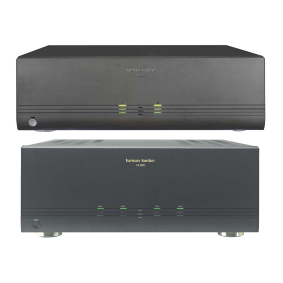
Harman Kardon PA2000 Service Manual
Multichannel amplifier
Hide thumbs
Also See for PA2000:
- Owner's manual (16 pages) ,
- Brochure & specs (40 pages) ,
- Brochure (2 pages)

Related Manuals for Harman Kardon PA2000


Summary of Contents for Harman Kardon PA2000
-
Page 1: Service Manual
PA2000 Models PA4000 MULTICHANNEL AMPLIFIER SERVICE MANUAL harman/kardon, Inc. 250 Crossways Park Dr. Woodbury, New York 11797 Rev0 11/2003... - Page 2 - CONTENTS - SPECIFICATIONS – PA2000/4000………………………..…………...……..2 PA2000 CONTROLS……………………………………………….……….…..3 PA2000 REAR PANEL………………………………………………..…….…..4 PA2000 INSTALLATION/CONNECTIONS……………………….…….……..5 PA2000 OPERATION…………………………………………………….……..9 PA2000 SERVICE & TROUBLESHOOTING……………..………..………..10 PA4000 CONTROLS……………………………………………….…………..11 PA4000 REAR PANEL……………………………………………………..…..12 PA4000 INSTALLATION/CONNECTIONS…………………………………..14 PA4000 OPERATION…………………………………………………………..19 PA4000 SERVICE & TROUBLESHOOTING……………..………………….20 PA4000 IDLE CURRENT ADJUSTMENT………………………………..…..21 PA2000 BLOCK DIAGRAM…………………………………………..………..22 PA4000 BLOCK DIAGRAM……………………………………..…………..…23 PA2000 EXPLODED VIEW……………………………………………..……..24...
-
Page 3: Specifications
PA2000/PA4000 harman/kardon SPECIFICATIONS PA2000 Power Output Normal Mode……………4 × 45 watt @ 8 ohms, 20 Hz ~ 20 kHz, < 0.07% THD, all channels driven Bridged Mode………….2 × 100 watt @ 8 ohms, 20 Hz ~ 20 kHz, < 0.07% THD, all channels driven High-Current Capability………………………………..………………………………………±45 amps... -
Page 4: Front Panel Controls And Indicators
PA2000 harman/kardon Front Panel Controls and Indicators CH 1 CH 2 Power Standby Protect Power 1 Power Switch 3 Standby Indicators 2 Power Indicators 4 Protect Indicators 1 Power Switch: Press this switch to turn the PA 2000 on for manual operation when the Power Control Mode Switch £... -
Page 5: Rear Panel Connections
PA2000 harman/kardon Rear Panel Connections 260W ¡ ™ £ ¢ £ ∞ § ¶ • ª ¡ Input Jacks § Trigger Jack ™ Output Jacks ¶ Channel 1 Output Speaker Terminals £ Power Control Mode Switches • Channel 2 Output Speaker Terminals ¢... -
Page 6: Installation And Configuration
PA2000 harman/kardon Installation and Configuration SAFETY NOTE: When making connections between any source components such 2b.To trigger the amplifier using the switched as AV receivers, surround processors or AC accessory outlet on an AV receiver or multiroom controllers and the PA 2000,... -
Page 7: Channel Configuration And Speaker Connections
PA2000 harman/kardon Channel Configuration and Speaker Connections Two-Pair Output One-Pair Output (Bridged Operation) For use in multiroom applications, the PA 2000 The PA 2000 is a bridgeable amplifier, which may be used to send the same signal feed to means that the two pairs of medium-powered two separate locations, such as living room and amplifiers may also be combined, or “bridged”,... -
Page 8: Speaker Wire Connections
PA2000 harman/kardon Speaker Wire Connections Regardless of the channel configuration used, Then, loosen the knobs of the speaker output Finally, connect the wires to the speakers, the final step of the installation process is to terminals far enough so that the pass-through again, being certain to observe proper polarity. -
Page 9: Audio Signal Connections
PA2000 harman/kardon Audio Signal Connections Audio connections for the PA 2000 are straight- forward: connect the output of the source unit, which may be the multiroom outputs of an AV receiver or “whole-house” audio system or the rear surround outputs of a processor or a receiver to the audio Input Jacks ¡. - Page 10 PA2000 harman/kardon Operation Operation of the PA 2000 is simple. In normal SAFETY NOTE: To prevent unintended opera- use, there are no controls to adjust once the tion, remember to turn the unit completely off installation is complete. when it will not be used for an extended period of time.
-
Page 11: Service Information
The items listed below are a brief guide to minor problems that may arise with audio equipment such as the PA 2000. Before taking a unit in for service, you should check to see whether any of these hints solve the problem. If these solutions do not rectify the problem or if the problem recurs, contact your dealer or an authorized Harman Kardon service depot for assistance. SYMPTOM... - Page 12 PA4000 harman/kardon Front-Panel Controls and Indicators PA 4000 CH 1 CH 2 CH 3 CH 4 Power Stand by Protect Power 1 Power Switch 3 Standby Indicators 2 Power Indicators 4 Protect Indicators 1 Power Switch: Press this switch to turn the PA 4000 on for manual operation when the Power Control Mode Switch ·...
- Page 13 PA 4000 is used in conjunction with a compati- ™ Channel 3 Speaker Terminals: Connect ble Harman Kardon AVR with multiroom capa- nected to these input jacks will be sent to all these terminals to the speaker pair that is fed by...
- Page 14 PA4000 harman/kardon Rear-Panel Connections ‹ Remote IR Sensor Inputs: When optional • When the switch is in the left position, below the phrase “BRIDGE 2”, the Channel 3 and remote IR sensors are used to control another Channel 4 amplifiers will be bridged together piece of equipment, connect them to these to operate as a single amplifier.
- Page 15 PA4000 harman/kardon Installation and Configuration SAFETY NOTE: When making connections 2a.To trigger the amplifier from a device such In this configuration, the PA 4000 will automat- between any source components such as a preamp surround processor or multi- ically turn on whenever it is receiving an audio as AV receivers, surround processors or room controller with a built-in trigger jack, input signal.
-
Page 16: Channel Configurations
PA4000 harman/kardon Channel Configurations and Audio Connections Channel Configurations, Audio where one room requires a high-power feed, “Bridge 1” should be used, with the connec- Connections and Speaker Connections while two other rooms may be fed a separate tions to the proper “+” and “–“ terminals with The PA 4000 is a versatile multichannel, multi- source with a lower power feed. - Page 17 PA4000 harman/kardon Channel Configurations and Audio Connections In addition to the speaker connections, the Two Inputs/Three Outputs are to receive this signal to the speaker ter- following steps must be followed for this con- In this configuration, there are three speaker minals marked “Bridge 1”, as shown in figuration: pair outputs, with one high-power and one...
- Page 18 PA4000 harman/kardon Channel Configurations and Audio Connections Speaker Wire Connections Then, loosen the knobs of the speaker output again, being certain to observe proper polarity. Regardless of the channel configuration used, terminals far enough so that the pass-through Remember to connect your “negative” or the final step of the installation process is to hole is revealed.
-
Page 19: System Connections
IR remote control commands from remote rooms and, where Harman Kardon AV receiver, such as the compatible, using them to control other source- AVR 7000, AVR 510 or AVR 310, you may also use the remote room IR commands to turn the control components. -
Page 20: Operation
PA4000 harman/kardon Operation Operation of the PA 4000 is simple. In normal automatic turn-on circuits from accidentally Turn-On Volume Level Limits use, there are no controls to adjust once the turning the amplifier on during your absence. In normal operation, when any channel pair in installation is complete. -
Page 21: Service And Troubleshooting
Harman Kardon recurs, contact your dealer or an authorized • Reconnect the power cord and turn the ampli- service center. - Page 22 PA4000 harman/kardon Idle Current Adjustment Procedure 1. Test Equipment Required -DC Voltmeter Note: Disconnect external Audio Generator prior to alignment. 2. Preparation 1. Confirm the AC Power Voltage. 2. Cool the Amplifier enough prior to alignment. 3. Disconnect external Audio Generator and Road Registers. 4.
- Page 23 PA 2000 BLOCK DIAGRAM...
- Page 24 PA 4000 BLOCK DIAGRAM...
- Page 25 PARTS NAME PART NO Q'TY REMARK PANNEL FRONT MEAF-06640-011 PANEL SIDE-L MJAF-09050-013 MJAF-06630-001 PANEL SUB HI-PS KNOB-POWER MJAF-17270-014 REDIATOR MAIN MEAC-05100-002 TRANSISTOR-MICA MRAG-14030-004 MICA BRACKET-RADIATOR(S) MPAC-16220-004 SECC CHASSIS-BOTTOM MPAC-04812-002 US-CO POWER-TRANS PTAP-03820-CJU CORD-AC KDAC-0578D-WGU CHASSIS-BACK MPAC-05090-012 SECC CHASSIS-TOP MPAC-04950-012 RADIATOR-IC MEAC-16960-004 PLATE-BACK MAAF-17490-004...
- Page 26 PARTS NAME PART NO Q'TY REMARK LED P. C. BOARD POWER P. C. BOARD FRONT P. C. BOARD AMP P. C. BOARD MAIN P. C. BOARD MI-COM P. C. BOARD AC-INLET P. C. BOARD INPUT P. C. BOARD 13 14 PA-4000 EXPLODED-VI E W PARTS NAME...
- Page 32 DISASSEMBLY PROCEDURE PA2000/4000 REFER TO THE EXPLODED VIEW ON PAGE (1) CHASSIS-TOP(20) REMOVAL. REMOVE 9 SCREWS (A : 5EA, J : 4EA) AND REMOVE THE CHASSIS-TOP(20) (2) FRONT PANEL ASS'Y(AA) REMOVAL. 1. REMOVE THE CHASSIS-TOP(20), REFERRING TO THE PREVIOUS STEP(1) 2.
- Page 33 DISASSEMBLY PROCEDURE CONT’D PA2000/4000 (6) INPUT P. C. BOARD(h) REMOVAL. 1. REMOVE THE CHASSIS-TOP(20), REFERRING TO THE PREVIOUS STEP(1) 2. REMOVE THE CHASSIS-BACK, REFERRING TO THE PREVIOUS STEP(5) 3. DISCONNECT THE CONNECTOR(CP2) FROM LEAD WIRE(CW102) ON THE INPUT P.C. BOARD(h) 4.
- Page 34 DISASSEMBLY PROCEDURE CONT’D PA2000/4000 (9) RADIATOR ASS'Y(AB) REMOVAL(LEFT SIDE). 1. REMOVE THE CHASSIS-TOP(20), REFERRING TO THE PREVIOUS STEP(1) 2. REMOVE THE FRONT-PANEL ASS'Y(AA), REFERRING TO THE PREVIOUS STEP(2) 3. REMOVE THE CHASSIS-FRONT, REFERRING TO THE PREVIOUS STEP(3) 4. REMOVE THE CHASSIS-SIDE, REFERRING TO THE PREVIOUS STEP(4) 5.
- Page 35 PA 2000 REF NO. PART NO. DESCRIPTION MECHANISM FGFB-O2002-831 FUSE GLASS 2A 125V 51S FGFB-O2002-831 FUSE GLASS 2A 125V 51S FGFB-O8001-831 FUSE GLASS 800mA 125V 51S F301 FGFB-O8002-831 FUSE GLASS 125V 5x20 U/C SB KDAC-0578D-WGU CORD AC KC-045,KC-003 1.8M BLK MAAF-17250-014 LENS-POWER PA-2000...
- Page 36 PA 2000 REF NO. PART NO. DESCRIPTION MECHANISM YSAP-12070-002 CUSHION-L/R YVAP-01862-014 POLY-BAG-I(G) TCS-1010 YVAP-13320-014 TOILON-SHEET PA-2000 750x1200, 0.5t 7JJG-00212-001 PACKING WRAP 500mm*1400m MAIN PCB CEET-J4R7M-CI0 CAPACITOR E/ALUMINUM 4.7uF M 50V 5x11 CCAT-J101K-AAB CAPACITOR CERAMIC 100PF K 50V B T CEET-J4R7M-CI0 CAPACITOR E/ALUMINUM 4.7uF M 50V 5x11 CCAT-J101K-AAB...
- Page 37 PA 2000 REF NO. PART NO. DESCRIPTION MAIN PCB CFMT-S104K-GI0 CAPACITOR F/POLYESTR 0.1uF K 250V 9.5x11 TL CFMT-S104K-GI0 CAPACITOR F/POLYESTR 0.1uF K 250V 9.5x11 TL CFMT-S104K-GI0 CAPACITOR F/POLYESTR 0.1uF K 250V 9.5x11 TL CFMT-S104K-GI0 CAPACITOR F/POLYESTR 0.1uF K 250V 9.5x11 TL CEEZ-L154M-SW2 CAPACITOR E/ALUMINUM 15000uF M 63V 35x60...
- Page 38 PA 2000 REF NO. PART NO. DESCRIPTION MAIN PCB CP10 KNCW-00970-3T9 CONNECTOR-WAFER JE202-1T-3P DDTS-00070-SO0 DIODE-SI 1SS133 (40V 0.11A) DO-40 T DDTS-00070-SO0 DIODE-SI 1SS133 (40V 0.11A) DO-40 T DDTR-00040-T10 DIODE-RECTIFIER 1N4004S(400V 1A 0.6mm) T DDTS-00070-SO0 DIODE-SI 1SS133 (40V 0.11A) DO-40 T DD4B-00360-VA0 DIODE-BRIDGE D15XB60H...
- Page 39 PA 2000 REF NO. PART NO. DESCRIPTION MAIN PCB TRTC-0039Y-SD0 TRANSISTOR N-H FREQ KTC3205-Y TO92L TRTC-0039Y-SD0 TRANSISTOR N-H FREQ KTC3205-Y TO92L TRTC-02050-SD0 TRANSISTOR N-H FREQ KRC120M W/RESIST TO92M TRTC-02050-SD0 TRANSISTOR N-H FREQ KRC120M W/RESIST TO92M TRTC-02050-SD0 TRANSISTOR N-H FREQ KRC120M W/RESIST TO92M TRTC-02050-SD0 TRANSISTOR N-H FREQ KRC120M W/RESIST TO92M...
- Page 40 PA 2000 REF NO. PART NO. DESCRIPTION MAIN PCB RCFT-E221J-000 RESISTOR-CARBON FILM 220ohm 1/5W 5% T RCFT-E683J-000 RESISTOR-CARBON FILM 68Kohm 1/5W 5% T RCFT-E221J-000 RESISTOR-CARBON FILM 220ohm 1/5W 5% T RCFT-E683J-000 RESISTOR-CARBON FILM 68Kohm 1/5W 5% T RCFT-E472J-000 RESISTOR-CARBON FILM 4.7Kohm 1/5W 5% T RCFT-E472J-000 RESISTOR-CARBON FILM...
- Page 41 PA 2000 REF NO. PART NO. DESCRIPTION MAIN PCB RCFT-E473J-000 RESISTOR-CARBON FILM 47Kohm 1/5W 5% T RCFT-E683J-000 RESISTOR-CARBON FILM 68Kohm 1/5W 5% T RCFT-E104J-000 RESISTOR-CARBON FILM 100Kohm 1/5W 5% T RCFT-E332J-000 RESISTOR-CARBON FILM 3.3Kohm 1/5W 5% T RCFT-E152J-000 RESISTOR-CARBON FILM 1.5Kohm 1/5W 5% T RCFT-E273J-000 RESISTOR-CARBON FILM...
- Page 42 PA 2000 REF NO. PART NO. DESCRIPTION MAIN PCB VOL1 VRBE-D033B-503 VR-ROTARY RK14K12B020653B 50KBx2 VOL2 VRBE-D033B-503 VR-ROTARY RK14K12B020653B 50KBx2 KTRE-00171-042 RESONATOR CST4.19MGW-TF01 MEAC-16960-004 RADIATOR-IC MMAC-12060-004 TERMINAL-GND XSTB-30080-ZB4 SCREW-TAPPING BHT2T 3x8 FE-ZB AMP PCB C301 CACS-S472M-200 CAPACITOR AC KH DE1310E 472M 250V P10mm C401 CEET-F220M-CI0 CAPACITOR E/ALUMINUM...
- Page 43 PA 2000 REF NO. PART NO. DESCRIPTION AMP PCB C561 CEET-J331M-HL1 CAPACITOR E/ALUMINUM 330uF M 50V 10x16 SHL T C562 CEET-J331M-HL1 CAPACITOR E/ALUMINUM 330uF M 50V 10x16 SHL T C563 CCAT-J120J-AAC CAPACITOR CERAMIC 12PF J 50V C T C564 CFMT-L334J-EGN CAPACITOR F/POLYESTR EB 0.33uF J 50V 7.2x9.5 T C565...
- Page 44 PA 2000 REF NO. PART NO. DESCRIPTION AMP PCB MPR451 RMFS-LR27J-0J0 RESISTOR-METAL PLATE 0.27ohm 5W 5% MPR-55R MPR501 RMFS-LR27J-0J0 RESISTOR-METAL PLATE 0.27ohm 5W 5% MPR-55R MPR551 RMFS-LR27J-0J0 RESISTOR-METAL PLATE 0.27ohm 5W 5% MPR-55R PCB1 PCSA-05570-11B PCB-SINGLE A1A-557 330x247x1.6t Q401 TRTA-0011G-SD0 TRANSISTOR P-H FREQ KTA1268-GR TO92...
- Page 45 PA 2000 REF NO. PART NO. DESCRIPTION AMP PCB Q561 TRSC-01540-SJ0 TRANSISTOR N-H FREQ 2SC4883A Q562 TRSA-01450-SJ0 TRANSISTOR N-H FREQ 2SA1859A Q565 TRTC-0015G-SD0 TRANSISTOR N-H FREQ KTC3200-GR TO92 Q567 TRTC-01700-SD0 TRANSISTOR N-H FREQ KRC107M W/RESIST TO92M Q568 TRTA-0011G-SD0 TRANSISTOR P-H FREQ KTA1268-GR TO92 Q569...
- Page 46 PA 2000 REF NO. PART NO. DESCRIPTION AMP PCB R465 RCFT-E561J-000 RESISTOR-CARBON FILM 560ohm 1/5W 5% T R466 RCFT-E561J-000 RESISTOR-CARBON FILM 560ohm 1/5W 5% T R467 RCFT-E472J-000 RESISTOR-CARBON FILM 4.7Kohm 1/5W 5% T R468 RCFT-E561J-000 RESISTOR-CARBON FILM 560ohm 1/5W 5% T R469 RCFT-F820J-010 RESISTOR-CARBON FILM...
- Page 47 PA 2000 REF NO. PART NO. DESCRIPTION AMP PCB R540 RCFT-E334J-000 RESISTOR-CARBON FILM 330Kohm 1/5W 5% T R541 RCFT-G152J-190 RESISTOR-CARBON FILM 1.5Kohm 1/2W 5% 2.3x6.5 T R542 RCFT-G152J-190 RESISTOR-CARBON FILM 1.5Kohm 1/2W 5% 2.3x6.5 T R543 RCFT-E225J-000 RESISTOR-CARBON FILM 2.2Mohm 1/5W 5% T R551 RCFT-E102J-000 RESISTOR-CARBON FILM...
- Page 48 PA 4000 REF NO. PART NO. DESCRIPTION ASS'Y SUB ZBNG-00400-0ZL BOND-ADHESIVE SC-306 ZBNG-01300-5ZL LOCKER-SCREW #1401B ASS'Y MECHA AC-CORD1 KDAC-0580D-WGU AC POWER CORD SET AC125V/13A 2BL POL UL/CSA LLA3-18161-000 CARD CABLE 18/160 1.25mm LLA3-22101-000 CARD CABLE 22/100 1.25mm LLA3-22101-000 CARD CABLE 22/100 1.25mm FGFB-O8002-831 FUSE GLASS...
- Page 49 PA 4000 REF NO. PART NO. DESCRIPTION ASS'Y MECHA Q414-1 TRSA-01770-SD0 TRANSISTOR P-H FREQ 2SA1943 Q414-2 TRSA-01770-SD0 TRANSISTOR P-H FREQ 2SA1943 Q459-1 TRSC-01680-SB0 TRANSISTOR N-H FREQ 2SC4137 TO-126FP Q459-2 TRSC-01680-SB0 TRANSISTOR N-H FREQ 2SC4137 TO-126FP Q463-1 TRSA-01780-SD0 TRANSISTOR N-H FREQ 2SC5200 Q463-2 TRSA-01780-SD0...
- Page 50 PA 4000 REF NO. PART NO. DESCRIPTION ASS'Y MAIN PCB C822 CEET-J1R0M-CI0 CAPACITOR E/ALUMINUM 1.0uF M 50V 5x11 C823 CEET-J1R0M-CI0 CAPACITOR E/ALUMINUM 1.0uF M 50V 5x11 C824 CEET-C471M-FI1 CAPACITOR E/ALUMINUM 470uF M 6.3V 8x11.5 U T C825 CEET-C471M-FI1 CAPACITOR E/ALUMINUM 470uF M 6.3V 8x11.5 U T C826 CFMT-N473J-GK0...
- Page 51 PA 4000 REF NO. PART NO. DESCRIPTION ASS'Y MAIN PCB KNCW-00970-4T9 CONNECTOR-WAFER JE202-1T-4P KNCW-00970-3T9 CONNECTOR-WAFER JE202-1T-3P KNCW-00970-3T9 CONNECTOR-WAFER JE202-1T-3P KNCW-00140-2TM CONNECTOR-WAFER 5267-02A 2.5mm MILK KNCW-00140-2TM CONNECTOR-WAFER 5267-02A 2.5mm MILK CP10 KNCW-00240-DT9 CONNECTOR-WAFER 53014-13 2.0mm WHT CP11 KNCW-00240-DT9 CONNECTOR-WAFER 53014-13 2.0mm WHT CP12 KNCW-00760-IT0 CONNECTOR-WAFER...
- Page 52 PA 4000 REF NO. PART NO. DESCRIPTION ASS'Y MAIN PCB R843 RCFT-E472J-000 RESISTOR-CARBON FILM 4.7Kohm 1/5W 5% T R844 RCFT-E103J-000 RESISTOR-CARBON FILM 10Kohm 1/5W 5% T R845 RCFT-E472J-000 RESISTOR-CARBON FILM 4.7Kohm 1/5W 5% T R846 RCFT-E103J-000 RESISTOR-CARBON FILM 10Kohm 1/5W 5% T R847 RCFT-E472J-000 RESISTOR-CARBON FILM...
- Page 53 PA 4000 REF NO. PART NO. DESCRIPTION ASS'Y AMP PCB C459 CEET-J331M-HL1 CAPACITOR E/ALUMINUM 330uF M 50V 10x16 SHL T C460 CFMT-L334J-EGN CAPACITOR F/POLYESTR EB 0.33uF J 50V 7.2x9.5 T C461 CFMT-L334J-EGN CAPACITOR F/POLYESTR EB 0.33uF J 50V 7.2x9.5 T C501 CEET-F220M-CI0 CAPACITOR E/ALUMINUM...
- Page 54 PA 4000 REF NO. PART NO. DESCRIPTION ASS'Y AMP PCB R403 RCFT-E271J-000 RESISTOR-CARBON FILM 270ohm 1/5W 5% T R404 RCFT-E271J-000 RESISTOR-CARBON FILM 270ohm 1/5W 5% T R405 RCFT-E201J-000 RESISTOR-CARBON FILM 200ohm 1/5W 5% T R406 RCFT-E333J-000 RESISTOR-CARBON FILM 33Kohm 1/5W 5% T R407 RCFT-E172F-000 RESISTOR-CARBON FILM...
- Page 55 PA 4000 REF NO. PART NO. DESCRIPTION ASS'Y AMP PCB R479 RMOH-H100J-100 RESISTOR-METAL OXIDE PRO1 1W 10ohm 5% R-SHAPE T R480 RCFT-E333F-000 RESISTOR-CARBON FILM 33Kohm 1/5W 1% T R481 RMOH-H330J-100 RESISTOR-METAL OXIDE PR01 1W 33ohm 5% R-SHAPE T R482 RMOH-H330J-100 RESISTOR-METAL OXIDE PR01 1W 33ohm 5% R-SHAPE T R483...
- Page 56 PA 4000 REF NO. PART NO. DESCRIPTION ASS'Y AMP PCB R569 RCFT-E183J-000 RESISTOR-CARBON FILM 18Kohm 1/5W 5% T R570 RCFT-E183J-000 RESISTOR-CARBON FILM 18Kohm 1/5W 5% T R571 RCFT-E821J-000 RESISTOR-CARBON FILM 820ohm 1/5W 5% T R572 RCFT-E821J-000 RESISTOR-CARBON FILM 820ohm 1/5W 5% T R573 RCFT-E122J-000 RESISTOR-CARBON FILM...
- Page 57 PA 4000 REF NO. PART NO. DESCRIPTION ASS'Y AMP PCB Q519 TRSC-01540-SJ0 TRANSISTOR N-H FREQ 2SC4883A Q520 TRSA-01450-SJ0 TRANSISTOR N-H FREQ 2SA1859A Q551 TRTA-0011G-SD0 TRANSISTOR P-H FREQ KTA1268-GR TO92 Q552 TRTA-0011G-SD0 TRANSISTOR P-H FREQ KTA1268-GR TO92 Q553 TRTA-0011G-SD0 TRANSISTOR P-H FREQ KTA1268-GR TO92 Q554...
- Page 58 PA 4000 REF NO. PART NO. DESCRIPTION ASS'Y INPUT PCB CCAT-J101K-AAB CAPACITOR CERAMIC 100PF K 50V B T CCAT-J101K-AAB CAPACITOR CERAMIC 100PF K 50V B T CEET-F330M-CI0 CAPACITOR E/ALUMINUM 33uF M 25V 5x11 CCAT-J101K-AAB CAPACITOR CERAMIC 100PF K 50V B T CEET-F330M-CI0 CAPACITOR E/ALUMINUM 33uF M 25V 5x11...
- Page 59 PA 4000 REF NO. PART NO. DESCRIPTION ASS'Y INPUT PCB CEET-F470M-CI0 CAPACITOR E/ALUMINUM 47uF M 25V 5x11 CEET-G471M-HN1 CAPACITOR E/ALUMINUM 470uF M 35V 13x16 U T CEET-F470M-CI0 CAPACITOR E/ALUMINUM 47uF M 25V 5x11 CFMT-N473J-GK0 CAPACITOR F/POLYESTR 0.047uF J 100V 8.9x13. T CEET-F220M-CI0 CAPACITOR E/ALUMINUM 22uF M 25V 5x11...
- Page 60 PA 4000 REF NO. PART NO. DESCRIPTION ASS'Y INPUT PCB DDTR-00040-T10 DIODE-RECTIFIER 1N4004S(400V 1A 0.6mm) T DDTR-00040-T10 DIODE-RECTIFIER 1N4004S(400V 1A 0.6mm) T DDTR-00040-T10 DIODE-RECTIFIER 1N4004S(400V 1A 0.6mm) T DDTS-00070-SO0 DIODE-SI 1SS133 (40V 0.11A) DO-40 T DDTZ-G051B-SOS DIODE ZENER MTZJ5.1B 4.94-5.20 DO34 T DDTS-00070-SO0 DIODE-SI 1SS133 (40V 0.11A) DO-40 T...
- Page 61 PA 4000 REF NO. PART NO. DESCRIPTION ASS'Y INPUT PCB RCFT-E101J-000 RESISTOR-CARBON FILM 100ohm 1/5W 5% T RCFT-E101J-000 RESISTOR-CARBON FILM 100ohm 1/5W 5% T RCFT-E102J-000 RESISTOR-CARBON FILM 1Kohm 1/5W 5% T RCFT-E104J-000 RESISTOR-CARBON FILM 100Kohm 1/5W 5% T RCFT-E104J-000 RESISTOR-CARBON FILM 100Kohm 1/5W 5% T RCFT-E821J-000 RESISTOR-CARBON FILM...
- Page 62 PA 4000 REF NO. PART NO. DESCRIPTION ASS'Y INPUT PCB RCFT-E822J-000 RESISTOR-CARBON FILM 8.2Kohm 1/5W 5% T RCFT-E152J-000 RESISTOR-CARBON FILM 1.5Kohm 1/5W 5% T RCFT-E152J-000 RESISTOR-CARBON FILM 1.5Kohm 1/5W 5% T RCFT-E104J-000 RESISTOR-CARBON FILM 100Kohm 1/5W 5% T RCFT-E152J-000 RESISTOR-CARBON FILM 1.5Kohm 1/5W 5% T RCFT-E104J-000 RESISTOR-CARBON FILM...
- Page 63 PA 4000 REF NO. PART NO. DESCRIPTION ASS'Y INPUT PCB R129 RCFT-E153J-000 RESISTOR-CARBON FILM 15Kohm 1/5W 5% T R130 RCFT-E472J-000 RESISTOR-CARBON FILM 4.7Kohm 1/5W 5% T R131 RCFT-E102J-000 RESISTOR-CARBON FILM 1Kohm 1/5W 5% T R132 RCFT-E102J-000 RESISTOR-CARBON FILM 1Kohm 1/5W 5% T R133 RCFT-E102J-000 RESISTOR-CARBON FILM...
- Page 64 PA 4000 REF NO. PART NO. DESCRIPTION ASS'Y INPUT PCB TRTC-0016Y-SD0 TRANSISTOR N-H FREQ KTC3198-Y TO92 TRTC-01700-SD0 TRANSISTOR N-H FREQ KRC107M W/RESIST TO92M TRTA-00810-SB0 TRANSISTOR P-H FREQ DTA114YSA W/RESIST SPT TRTA-00810-SB0 TRANSISTOR P-H FREQ DTA114YSA W/RESIST SPT TRTA-00810-SB0 TRANSISTOR P-H FREQ DTA114YSA W/RESIST SPT TRTC-0016Y-SD0 TRANSISTOR N-H FREQ...
- Page 65 PA4000 Ref. No. Part No. Description ASS'Y MI-COM PCB C303 CCAT-J104Z-AAF CAPACITOR CERAMIC 0.1uF Z 50V F T C305 CCAT-J104Z-AAF CAPACITOR CERAMIC 0.1uF Z 50V F T C312 CCAT-J104Z-AAF CAPACITOR CERAMIC 0.1uF Z 50V F T C314 CCAT-J104Z-AAF CAPACITOR CERAMIC 0.1uF Z 50V F T C316 CCAT-J104Z-AAF CAPACITOR CERAMIC 0.1uF Z 50V F T...
- Page 66 PA4000 Ref. No. Part No. Description ASS'Y MI-COM PCB D318 DDTS-00070-SO0 DIODE-SI 1SS133 (40V 0.11A) DO-40 T D319 DDTS-00070-SO0 DIODE-SI 1SS133 (40V 0.11A) DO-40 T D320 DDTS-00070-SO0 DIODE-SI 1SS133 (40V 0.11A) DO-40 T D321 DDTS-00070-SO0 DIODE-SI 1SS133 (40V 0.11A) DO-40 T D322 DDTS-00070-SO0 DIODE-SI...
- Page 67 PA4000 Ref. No. Part No. Description ASS'Y MI-COM PCB R364 RCFT-E271J-000 RESISTOR-CARBON FILM270ohm 1/5W 5% T R368 RCFT-E271J-000 RESISTOR-CARBON FILM270ohm 1/5W 5% T R345 RCFT-E301J-000 RESISTOR-CARBON FILM300ohm 1/5W 5% T R349 RCFT-E301J-000 RESISTOR-CARBON FILM300ohm 1/5W 5% T R351 RCFT-E301J-000 RESISTOR-CARBON FILM300ohm 1/5W 5% T R355 RCFT-E301J-000 RESISTOR-CARBON FILM300ohm 1/5W 5% T...
- Page 68 PA4000 Ref. No. Part No. Description ASS'Y MI-COM PCB R371 RCFT-E472J-000 RESISTOR-CARBON FILM4.7Kohm 1/5W 5% T R372 RCFT-E472J-000 RESISTOR-CARBON FILM4.7Kohm 1/5W 5% T R373 RCFT-E472J-000 RESISTOR-CARBON FILM4.7Kohm 1/5W 5% T R374 RCFT-E472J-000 RESISTOR-CARBON FILM4.7Kohm 1/5W 5% T R375 RCFT-E472J-000 RESISTOR-CARBON FILM4.7Kohm 1/5W 5% T R376 RCFT-E472J-000 RESISTOR-CARBON FILM4.7Kohm 1/5W 5% T...
- Page 69 PA4000 Ref. No. Part No. Description ASS'Y MI-COM PCB Q311 TRTC-02050-SD0 TRANSISTOR N-H FREQ KRC120M W/RESIST TO92M Q312 TRTC-02050-SD0 TRANSISTOR N-H FREQ KRC120M W/RESIST TO92M UD08-3M845-250 WIRE-ASS'Y UL1007#28 ORG/BLK-450 13P ASS'Y SWITCH PCB C815 CACS-S472M-201 CAPACITOR AC KH DE1307E 472M P7.5mm CP15 KNCW-00990-4T9 CONNECTOR-WAFER...
-
Page 70: Ic Block Diagrams
PA 2000 / PA 4000 IC BLOCK DIAGRAMS A6802722 BLOCK DIAGRAM... - Page 71 PA 2000 / PA 4000 KIC9482N/F BLOCK DIAGRAM...
-
Page 72: Block Diagram
PA 2000 / PA 4000 KS57P0504 BLOCK DIAGRAM BASIC WATCH TIMER TIMER RESET Xout 8-BIT P0.0 / TIMER/ I/O PORT 0 P0.1 / SO COUNTER INTERRUPT STACK P0.2 / SI CONTROL CLOCK POINTER BLOCK P3.0 / TCL0 SERIAL I/O P3.1 / TCLO0 I/O PORT 3 PROGRAM PORT... - Page 73 PA 2000 / PA 4000 TC4094BP BLOCK DIAGRAM...
- Page 74 PA2000/PA4000 harman/kardon Quad buffer/line driver; 3-state 74HC/HCT125 PIN DESCRIPTION PIN NO. SYMBOL NAME AND FUNCTION 1, 4, 10, 13 1OE to 4OE outputs enable inputs (active LOW) 2, 5, 9, 12 1A to 4A data inputs 3, 6, 8, 11...
- Page 75 PA2000/PA4000 harman/kardon KA4558C DUAL OP-AMP KA7815 +15V REGULATOR KA7808 +8V REGULATOR KA7812 +12V REGULATOR KA7915 -15V REGULATOR KTC 3198 KTD 1302 KTC 120M KTC 3467 KTC 3200 KTC 3206 KRC 107M KTC 3205 KRC120M KTA 1024 KTA 1266 KTA1268 KRA107M...
-
Page 76: Printed Circuit Boards
PA 2000 PRINTED CIRCUIT BOARDS PCB LAYOUT - AMP... - Page 77 PA 2000 PCB LAYOUT - MAIN...
- Page 78 PCB LAYOUT - INPUT PA 4000...
- Page 79 PA 4000 PCB LAYOUT - MAIN...
- Page 80 PA 4000 PCB LAYOUT - MICOM...
- Page 82 PA 2000 SCHEMATIC DIAGRAM - MAIN...
- Page 83 SCHEMATIC DIAGRAM - MAIN PART 1...
- Page 84 PA 2000 SCHEMATIC DIAGRAM - MAIN PART 2...
- Page 85 PA 2000 SCHEMATIC DIAGRAM - CH4 AMP...
- Page 86 SCHEMATIC DIAGRAM - CH4 AMP...
- Page 87 PA 2000...
- Page 88 PA 4000 SCHEMATIC DIAGRAM - INPUT...
- Page 89 SCHEMATIC DIAGRAM - INPUT PART 1...
- Page 90 SCHEMATIC DIAGRAM - INPUT PART 2 PA 4000...
- Page 91 PA 4000 SCHEMATIC DIAGRAM - MAIN...
- Page 92 SCHEMATIC DIAGRAM - MAIN PART 1...
- Page 93 SCHEMATIC DIAGRAM - MAIN PART 2 PA 4000...
- Page 94 PA 4000 SCHEMATIC DIAGRAM - CH1 (CH3) / CH2 (CH4)
- Page 95 SCHEMATIC DIAGRAM - CH1 (CH3) / CH2 (CH4)
- Page 96 PA 4000 SCHEMATIC DIAGRAM - CH1 (CH3) / CH2 (CH4) PART 2...
- Page 97 PA 4000 SCHEMATIC DIAGRAM - MICOM...
- Page 98 SCHEMATIC DIAGRAM - MICOM PART 1...
- Page 99 SCHEMATIC DIAGRAM - MICOM PART 2 PA 4000...
-
Page 100: Wiring Diagrams
PA 2000 WIRING DIAGRAMS WIRING DIAGRAM... - Page 101 PA 2000 / 230 WIRING DIAGRAM...
- Page 102 PA 4000 WIRING DIAGRAM...
-
Page 103: Packing Material
PA 2000 PACKING MATERIAL... - Page 104 PA 4000...
Need help?
Do you have a question about the PA2000 and is the answer not in the manual?
Questions and answers