
Related Manuals for Electro-Voice DC-One


Summary of Contents for Electro-Voice DC-One
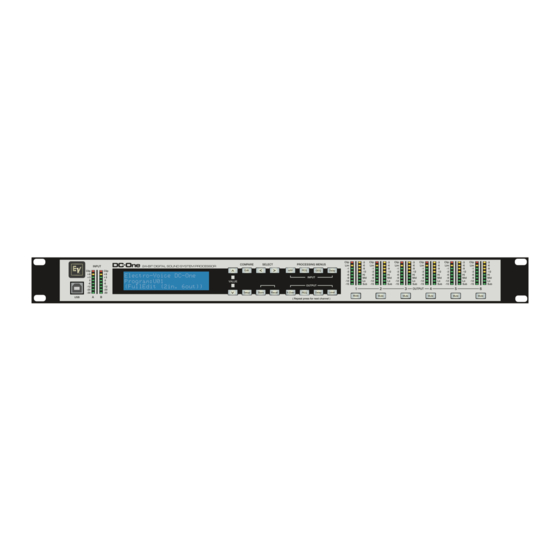
- Page 1 OWNER’S MANUAL BEDIENUNGSANLEITUNG > < Edit Delay Electro-Voice DC-One Program:U01 (FullEdit (2in. 6out)) Setup Store Recall X-Over Delay Level Mute Mute Mute Mute Mute Mute...
-
Page 2: Table Of Contents
Configurations of the DC-One ........ - Page 3 DC-One Ausstattungsmerkmale ........
-
Page 4: Important Safety Instructions
DC-One IMPORTANT SAFETY INSTRUCTIONS The lightning flash with arrowhead symbol, within an equilateral triangle is intended to alert the user to the presence of uninsulated “dangerous vol- tage“ within the product’s enclosure that may be of sufficent magnitude to constitute a risk of elec- tric shock to persons. - Page 5 DC-One Owner‘s Manual...
-
Page 6: Overview
DC-One 1 Overview Owner‘s Manual... - Page 7 DC-One Owner‘s Manual...
-
Page 8: Introduction
Recallable factory and user presets; instant system reconfiguration for differing applications and per- formances. • Easy, intuitive operation and editing with a PC and the DC-One Graphic User Interface Application. Each DC-One Digital System Processor includes the following signal processing blocks: •... - Page 9 DC-One Matrix Router / Mixer • Two inputs (stereo) • Summed left / right (mono) input • Six assignable outputs Outputs (each) • Cross-over (hi-pass / low-pass filters), with selectable filter types • 5-band parametric equalizer • Delay • Polarity •...
-
Page 10: Lcd Display
Optimal signal-to-noise performance is obtained when the nominal (average), input level consistently lights the +3dBu (green) and / or +6dBu (Yellow) LED indicators. As the DC-One is a digital audio device – and digital clipping produces very unpleasant results, the Clip (red) LED should not light. If the DC-One’s input does clip, reduce the output level of the connected mixer. - Page 11 DC-One screen. Use the Select buttons to activate the top line of the display, and the value buttons to scroll through available parameter edit screens. 4/5 – Value Up/Down Buttons Depending on the current LCD screen, the Value Up/Down Buttons performs the following function: •...
- Page 12 DC-One 10 – Store Button Pressing the Store button while in Run mode displays the Store Preset screen in the LCD display and the Store button lights. In this screen edited presets can be named and saved to a user preset location.
- Page 13 DC-One 16 – Output X-Over Button Pressing the X-Over button places the current preset in Edit mode and jumps to the first Output Channel Cross-Over screen. Subsequent button presses step through the available output channels (depending on configuration). 17 – Output PEQ Button Pressing the PEQ button places the current preset in Edit mode and jumps to the first Output Parametric Equalizer screen.
-
Page 14: Rear Panel
The button lights red as an alert. Press the Mute button again to restore the output channel’s signal. Output channels may also be muted from the DC-One Graphic User Interface Application, if the unit is connected to a PC. Muting a channel in any window of the application will light the channel Mute button on the front panel of the unit as well. - Page 15 The signal does not undergo any digital conversion or processing. These connectors are used to pass input audio to a second DC-One used as a slave or to other audio inputs in the system. 31 – Balanced XLR Inputs Each input has an electronically balanced, locking XLR connector.
-
Page 16: Power Connection
Power Connection The DC-One must be connected to A.C. power only by means of the provided IEC A.C. cable or by a power cable provided by the dealer / installer to match the configuration of your country or region. The DC- One must only be connected to a properly wired, three pin, grounded A.C. - Page 17 DC-One Un-balanced Input / Output Connections Un-balanced connections can be made to the DC-One, although induced noise from cabling may be increased. Cables should also be less than 15” (5m) in length. Unbalanced connections can be 6dB lower in level as well. To match the audio level obtained with a balanced connection, it is necessary to tie pin 3 to ground at the XLR connector.
-
Page 18: Connection To Amplifiers
Input Level Adjustment The final step in setting up, installing and connecting the DC-One is to set proper input levels to the unit. The DC-One does not itself have input level controls. Proper input level setting is accomplished by setting the output level from the (L / R) bus outputs from the connected mixer (or other audio output device). -
Page 19: Editing & Operation
The factory warranty for your DC-One is 36 months (3 years), from the date of purchase. Please save the warranty certificate and receipt; which must be presented at the time of warranty service for the factory warrantee to be valid. -
Page 20: Run-Time Mode
DC-One 5 Run-time Mode 5.1 LCD Display On power-up, the DC-One boots and displays the run-time screen. The current preset memory location and name are displayed as well as the configuration on which the preset is based. CAUTION Before operating the sound reinforcement system, and any time a new preset... -
Page 21: Output Gain Reduction Meters
Each output channel has a four-segment function display for informational purposes only. For any given configuration possible with the DC-One, an output channel may be identified as a sub, low, low/mid, mid, mid/hi, hi or full range output. One or two adjacent LED’s are displayed to indicate all possible output bandpasses. -
Page 22: Preset Store
Both Factory and User preset can be edited, but edited presets can only be stored in User preset locations. Standard Edit Mode The DC-One defaults to Standard Edit mode wherein, input and output channel parameters are appropriately linked. (Refer to “Configurations” illustrations to see which channels are parameter-linked for each configuration. -
Page 23: Parameter
Value Up and Down buttons to navigate to the Input Hi-Pass screen. The first DSP block in the DC-One’s signal flow is the stereo Hi-Pass Filter. In any sound reinforcement system, the Hi-Pass filter is crucial for maximizing the efficiency and performance of the PA system. -
Page 24: Input Channel Parametric Eq
Each band of the Input PEQ can be configured for a specific filter mode, frequency, slope or Q and gain setting. Attention must be paid to the ultimate output gain through the rest of the DC-One’s audio path, as it is possible to boost frequency ranges to the point where the internal or external audio paths of the system may be clipped. - Page 25 Keep in mind that the DC-One signal path already includes a hi-pass filter prior to the Input PEQ DSP block. Settings to this filter in most configurations may be redundant or interactive with the initial Hi-Pass filter.
- Page 26 Input GEQ screen. The DC-One’s input signal path includes a stereo 31-band graphic equalizer after the stereo 9-band PEQ in the signal path. This DSP block can be used for very precisely identifying, isolating and correcting problematic frequency ranges.
- Page 27 The DC-One crossover routes frequencies to the appropriate drivers to accurately reproduce sound. The crossover network can also be used to insure that low-frequency energy is not accidently routed to the mid-range or tweeter drivers that may result in potential damage.
- Page 28 Frequency offers a selectable frequency range from 20.0 Hz to 20,000Hz. Hi-Pass/Lo Pass The DC-One Hi-Pass and Lo-Pass filters are determined by selecting the Type from the list of parameters, (see list above) and by choosing a frequency range between 20.0 Hz to 20,000Hz. (See above) Illustration 5.2: Here the HiPass Output 2 Crossover is set to Linkwitz-Riley 24dB with the frequency set to...
- Page 29 0.40 to 2.00 Delay (Output Channels) DC-One’s output delays can be applied to output channels OUT1 - OUT6 and can be used to compensate for the positioning of cabinets or speaker arrays relative to each other or the original sound source.
- Page 30 Level parameters (-100.0dB to +6.0dB). Adjust the value by using the up/down VALUE arrows. Channel Limiter (Output Channels) DC-One‘s output channel limiters prevent audio signals from exceeding a set level. Press the Level button to change the output channel. Hold-down the Level button for some seconds - you will then be presented with the Limiter screen.
- Page 31 Limiter settings for your system and may result in system damage. If a non-Electro-Voice amplifier is used in the system, selecting “Other” from the amp list will allow the Threshold setting to be directly edited, however, the amplifier documentation should be consulted so you can calculate you limiter offset (if any) as needed.
-
Page 32: Setup
DC-One 6 Setup The Setup menu allows access DC-One’s global parameters on the LCD screen. This is where preferences for many functions can be set or adjusted. Pressing the Setup button brings up the first Setup window. Use the VALUE up/down arrows to scroll through the Setup menu: Use the <SELECT> buttons to scroll to Setup parameters to make adjustments using the VALUE up/down buttons. - Page 33 DC-One Input This window is where the global input mode is set. Use the <SELECT> key to navigate to the MODE parameter. Use the up/ down VALUE arrows to choose between Analog and Digital input. LCD settings allow the user to adjust the contrast preferences of the LCD screen to compensate for different lighting conditions that may be encountered within different venues.
- Page 34 (U## or F##), DSP Blocks and Parameters. Any or all of the DC-One’s DSP Blocks and/or individual parameters within the DSP blocks can be locked or hidden from this window by selecting the corresponding box to engage the lock icon.
- Page 35 RS-232 Port An RS-232 (DB-9 or ‘D-Sub’) connection is provided on the back panel to link to another DC-One to enable Master/Slave operation. Use the <SELECT> key to navigate to the MODE parameter and use the up/down VALUE arrows to choose between RS-232 and Contacts.
-
Page 36: Configurations Of The Dc-One
7 Configurations of the DC-One The DC-One offers 7 pre-defined configurations. A configuration is a basic setting that includes the routing of inputs and outputs, the function of the outputs (Sub, Lo, Mid, Hi, Full Range) including basic x-over filter settings, and different channel/parameter linking schemes. -
Page 37: Way Stereo + Full Range
DC-One 7.1 2-Way Stereo + Full Range This configuration generally represents a 2-way stereo frequency crossover, where IN A serves as the left input channel and IN B as the right input channel. OUT 1 is the left Low-frequency output and OUT 2 is the left High-frequency output. -
Page 38: Way Stereo
DC-One 7.2 3-Way Stereo This configuration represents a 3-way frequency crossover where IN A serves as the left input channel and IN B as the right input channel. OUTs 1 & 4 L/R are the Sub frequency channel, OUT 2 &5 L/R are Low and Mid-frequency channels, 3 &... -
Page 39: 4-Way + Fr
DC-One 7.3 4-Way + FR The 4-Way configuration is a monaural 4-way frequency x-over. Crossover channels are fed from IN A, full range channels are from IN B. OUT 1 is a mono Sub frequency channel, OUT 2 is a mono Low-frequency channel, OUT 3 is a mono Mid-frequency channel, and OUT 4 is the mono High-frequency. -
Page 40: 5-Way + Fr
DC-One 7.4 5-Way + FR The 5-Way configuration is a monaural 5-way frequency x-over. Crossover channels are fed from IN A, full range channels are fed from IN B. OUT 1 is a mono Sub frequency channel, OUT 2 the... -
Page 41: Eq Plot Images
DC-One 10 EQ Plot Images 10.1 6 dB PEQ Cuts Q Changes 10.2 6 dB-Oct Shelves at 200 Hz and 2 kHz Owner‘s Manual / Bedienungsanleitung... -
Page 42: Db Peq Cuts Q Changes
DC-One 10.3 12 dB PEQ Cuts Q Changes 10.4 12dB-Oct Shelves at 200 Hz and 2 kHz Owner‘s Manual / Bedienungsanleitung... -
Page 43: Bessel Filters
DC-One 10.5 Bessel Filters 10.6 Butterworth Filters Owner‘s Manual / Bedienungsanleitung... -
Page 44: Hi Lo Pass Filters
DC-One 10.7 Hi Lo Pass Filters 10.8 Linkwitz-Riley Filters Owner‘s Manual / Bedienungsanleitung... -
Page 45: Peq Gains
DC-One 10.9 PEQ Gains Owner‘s Manual / Bedienungsanleitung... - Page 46 DC-One Owner‘s Manual / Bedienungsanleitung...
- Page 47 Notes...
- Page 48 Notes...
- Page 49 Americas Asia & Pacific Rim Bosch Communications Systems Japan: EVI Audio Japan Ltd. 12000 Portland Ave South 5-3-8 Funabashi, Setagaya-Ku Burnsville, MN 55337, USA Tokyo, Japan 156-0055 USA: Phone:1-800-392-3497 Phone: +81 3-5316-5020 Fax: 1-800-955-6831 Fax: +81 3-5316-5031 Canada: Phone: 1-866-505-5551 Fax:1-866-336-8467 Latin America: Phone: 1-952-887-5532...
Need help?
Do you have a question about the DC-One and is the answer not in the manual?
Questions and answers