Brother HL-5240 Service Manual
Laser printer
Hide thumbs
Also See for HL-5240:
- User manual (138 pages) ,
- Quick setup manual (23 pages) ,
- Installation manual (17 pages)
Table of Contents
Advertisement
Quick Links
Advertisement
Table of Contents
Troubleshooting

Related Manuals for Brother HL-5240


Summary of Contents for Brother HL-5240
-
Page 1: Service Manual
Brother Laser Printer SERVICE MANUAL MODEL: HL-5240/5240L/5250DN/ 5270DN/5280DW Read this manual thoroughly before maintenance work. Keep this manual in a convenient place for quick and easy reference at all times. September 2005 SM-PRN057 (17) Confidential... - Page 2 Ltd., covering the latest product descriptions and specifications. The contents of this manual and the specifications of this product are subject to change without notice. Brother reserves the right to make changes without notice in the specifications and materials contained herein...
- Page 3 (hereinafter referred to as "this machine" or "the printer"). This information is vital to the service technician to maintain the high printing quality and performance of the printer. This service manual covers the HL-5240/5250DN/5270DN/5280DW printers. This manual consists of the following chapters: CHAPTER 1: GENERAL Features, specifications, etc.
-
Page 4: Table Of Contents
TABLE OF CONTENTS REGULATION.....................viii SAFETY INFORMATION................x CHAPTER 1 GENERAL ................1-1 FEATURES .......................1-1 PARTS NAMES AND FUNCTIONS ................1-3 Overview .......................... 1-3 Control Panel ........................1-5 SPECIFICATIONS.....................1-7 Printing ..........................1-7 Functions.......................... 1-8 Electronics and Mechanics .................... 1-11 Service Information ......................1-12 Network Connectivity ..................... - Page 5 HL-5240/5250DN/5270DN/5280DW SERVICE MANUAL 2.3.9 Reset circuit ........................2-5 2.3.10 Panel I/O ..........................2-5 2.3.11 Video I/O ..........................2-5 2.3.12 Power supply........................2-5 2.3.13 Wireless LAN ........................2-5 Power Supply ........................2-6 2.4.1 Low-voltage power supply....................2-6 2.4.2 High-voltage power supply ....................2-6 MECHANICS ......................2-7...
- Page 6 PAPER PROBLEMS....................4-15 Paper Loading Problems ....................4-15 Paper Jams ........................4-16 3.2.1 Paper jams and how to clear them for HL-5240/5250DN ..........4-16 3.2.2 Paper jams and how to clear them for HL-5270DN/5280DW ........... 4-18 3.2.3 Causes & countermeasures ....................4-26 Paper Feeding Problems ....................
- Page 7 7.24 New Toner Actuator ....................... 5-41 7.25 Gear 17/20/23 ........................ 5-42 7.26 Side Cover R........................5-44 7.27-1 Top Cover Printed ASSY (For HL-5240/5250DN) ............5-45 7.27-2 Panel PCB ASSY ......................5-45 7.27-3 SW Key A/B........................5-46 7.27-4 Inner Chute/Pinch Roller Holder .................. 5-47...
- Page 8 7.28-1 Top Cover 2 Printed ASSY (For HL-5270DN/5280DW) ..........5-48 7.28-2 Inner Chute/Pinch Roller Holder .................. 5-49 7.28-3 Panel PCB ASSY ......................5-50 7.28-4 SW Key A/B/C/ Set Key Printed ASSY ................ 5-51 7.28-5 LCD Holder ASSY......................5-53 7.29 Filter ..........................5-55 7.30 Laser Unit........................
- Page 9 HL-5240/5250DN/5270DN/5280DW SERVICE MANUAL CHAPTER 6 ADJUSTMENTS AND UPDATING OF SETTINGS, REQUIRED AFTER PARTS REPLACEMENT....6-1 IF YOU REPLACE THE MAIN PCB ................6-1 IF YOU REPLACE THE PERIODICAL MAINTENANCE PARTS ......6-10 CHAPTER 7 SERVICE SUPPORT SOFTWARE........7-1 CONTROL PANEL ....................7-1 Users Mode........................7-1 User Maintenance Mode....................
-
Page 10: Regulation
Laser Notice No.50, dated July 26, 2001. The label for Chinese manufactured products MANUFACTURED: Brother Corporation (Asia) Ltd. Brother Buji Nan Ling Factory Gold Garden Ind., Nan Ling Village, Buji, Rong Gang, Shenzhen, CHINA... - Page 11 HL-5240/5250DN/5270DN/5280DW SERVICE MANUAL IEC 60825 (220-240V MODEL ONLY) This printer is a Class 1 laser product as defined in IEC 60825 specifications. The label shown below is attached in countries where it is required. This printer has a laser diode which emits invisible laser radiation in the Laser Unit. The Laser Unit should not be opened without disconnecting the two connectors connected with the AC power supply and laser unit.
-
Page 12: Safety Information
SAFETY INFORMATION CAUTION FOR LASER PRODUCT (WARNHINWEIS FUR LASER DRUCKER) CAUTION: When the machine during servicing is operated with the cover open, the regulations of VBG 93 and the performance instructions for VBG 93 are valid. CAUTION: In case of any trouble with the laser unit, replace the laser unit itself. To prevent direct exposure to the laser beam, do not try to open the enclosure of the laser unit. - Page 13 HL-5240/5250DN/5270DN/5280DW SERVICE MANUAL DEFINITIONS OF WARNINGS, CAUTIONS AND NOTES The following conventions are used in this service manual: WARNING Indicates warnings that must be observed to prevent possible personal injury. CAUTION: Indicates cautions that must be observed to service the printer properly or prevent damage to the printer.
-
Page 14: Chapter 1 General
HL-5240/5250DN/5270DN/5280DW SERVICE MANUAL CHAPTER 1 GENERAL FEATURES This printer has the following features. High Resolution and Fast Print Speed True 600 x 600 dots, true 300 x 300 dots per inch (dpi), HQ1200 and 1200 x 1200 dpi for graphics with microfine toner and up to 28 pages per minute (ppm) print speed for printing on A4 size paper, and up to 30 pages per minute (ppm) print speed for Letter- size paper. - Page 15 • Network Feature (for HL-5250DN/5270DN/5280DW) The Brother printer has built in multi protocol network capability as standard. This allows multiple host computers to share the printer on a 10/100Mb wired Ethernet or IEEE 802.11b/802.11g wireless Ethernet network. Any users can print their jobs as if the printer was ®...
-
Page 16: Parts Names And Functions
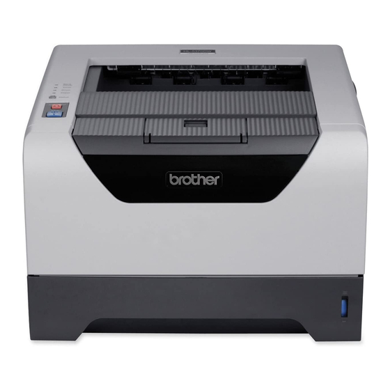
HL-5240/5250DN/5270DN/5280DW SERVICE MANUAL PARTS NAMES AND FUNCTIONS 2.1 Overview (HL-5240/5250DN) <Front View> Front cover release button Face-down output tray Front cover Control panel Face-down output tray support flap (support flap) MP tray cover ASSY Power switch Paper tray Multi-purpose tray (MP tray) Fig. -
Page 17: Front View
CHAPTER 1 GENERAL (HL-5270DN/5280DW) <Front View> Front cover release button Face-down output tray Front cover Control panel Face-down output tray support flap (support flap) MP tray cover ASSY Power switch Paper tray Multi-purpose tray (MP tray) Fig. 1-3 <Rear View> Back cover DIMM cover Duplex tray... -
Page 18: 2.2 Control Panel
HL-5240/5250DN/5270DN/5280DW SERVICE MANUAL 2.2 Control Panel (HL-5240/5250DN) There are the four Light Emitting Diodes (LEDs) (Toner, Drum, Paper and Status) and two control buttons (Go and Job Cancel) on the control panel. 1. Toner LED indicates when the Toner is low or at the end of its life. - Page 19 CHAPTER 1 GENERAL (HL-5270DN/5280DW) 1. LCD • Off: The printer is off or in sleep status. • Green (General): Ready to print. Printing Warming up Job canceling • Red (Error): There is a problem with the printer. • Orange (Setting): The printer is offline. Choosing a menu Setting number of reprints.
-
Page 20: Specifications
HL-5240/5250DN/5270DN/5280DW SERVICE MANUAL SPECIFICATIONS 3.1 Printing Print method Electrophotography by semiconductor laser beam scanning Laser Wavelength: 770 - 810nm Output: 5mW max Laser class: Class B Resolution <Windows 95, WindowsNT 4.0, Windows 98/Me, Windows 2000, ... -
Page 21: 3.2 Functions
16 MB (HL-5240) 32MB (HL-5250DN/5270DN/5280DW) <Option> DIMM (HL-5240) The HL-5240 printer has 16 MB of standard memory and one slot for optional memory expansion. You can expand the memory up to 528 MB by installing dual in-line memory modules (DIMMs). (HL-5250DN/5270DN/5280DW) The HL-5250DN/5270DN/5280DW printer has 32 MB of standard memory and one slot for optional memory expansion. - Page 22 95/98/Me, Windows NT <Macintosh > • Brother Laser Driver for Mac OS 9.1 to 9.2 and Mac OS 10.2.4 or greater • BR-Script 3 (PPD file) for Mac OS 9.1 to 9.2 and Mac OS 10.2.4 or greater...
- Page 23 CHAPTER 1 GENERAL Utilities (HL-5240) Interactive Help* (HL-5250DN/5270DN/5280DW) Interactive Help*, Driver Deployment Wizard** * Interactive Help: Instructional animations for problem solving. ** The Driver Deployment Wizard automates the installation of a printer in a peer-to-peer network. System Requirements Computer Platform & Operating...
-
Page 24: Electronics And Mechanics
Storage: 10 to 85% (non condensing) Dimensions (HL-5240/5250DN) <W x D x H> 371 x 384 x 246 mm (14.6 x 15.1 x 9.7 inches) (HL-5270DN/5280DW) <W x D x H> 393 x 384 x 259 mm (15.5 x 15.1 x 10.2 inches) -
Page 25: Service Information
Professional/XP Professional x64 Edition Professional NOTE: NC-6400h is a network controller of the printer built-in type. • NC-2100p (HL-5240) (Option) An optional network print server (NC-2100p) allows you to connect to your network through the parallel interface. Network interface 10/100BASE-TX Ethernet... - Page 26 Professional utilities 2000/XP BRAdmin Light Mac OS X 10.2.4 or greater Web BRAdmin Windows 2000 Professional / Server / Advanced Server, Windows XP Professional *1: Web BRAdmin are available as a download from http://solutions.brother.com. 1-13 Confidential...
-
Page 27: Paper
* Calculated with 80 g/m (21 lb) paper. All models Paper Output* Face-down 150 sheets * Calculated with 80 g/m (21 lb) paper. HL-5240 HL-5250DN/ 5270DN/ 5280DW Duplex Manual Duplex Automatic Duplex 3.6.2 Media specifications (1) Media types The printer loads paper from the installed paper tray or the multi-purpose tray. The feedable media type and size are different depending on the paper tray installed. - Page 28 HL-5240/5250DN/5270DN/5280DW SERVICE MANUAL Choose the Tray 1/2/3 MP Tray media type from the printer driver Plain paper Plain paper 75 g/m to 105 (20 to 28 lbs.) Recycled Recycled paper paper Bond paper Bond paper Rough paper- 60 g/m to 105...
- Page 29 CHAPTER 1 GENERAL (3) Media weights Tray 2/3 Tray 1 MP Tray Lower tray unit (Option) (LT-5300) 60 to 105 g/m 60 to 161 g/m 60 to 105 g/m 60 to 105 g/m (16 to 28 lb.) (16 to 43 lb.) (16 to 28 lb.) (16 to 28 lb.) (4) Recommended paper...
-
Page 30: Printable Area
HL-5240/5250DN/5270DN/5280DW SERVICE MANUAL Printable Area 3.7.1 PCL5e/EPSON/IBM emulation When using PCL emulation, the edges of the paper that cannot be printed on are shown below. Portrait Physical page Printable area Logical page Physical page length Maximum logical page length Distance from edge of physical page to... - Page 31 CHAPTER 1 GENERAL The table below shows the printable areas when printing on Portrait for each paper size. Size 215.9 mm 279.4 mm 203.2 mm 279.4 mm 6.35 mm 4.2 mm 8.5” 11.0” 8.0” 11.0” 0.25” 0 mm 0.16” Letter (2,550 dots) (3,300 dots) (2,400 dots)
- Page 32 HL-5240/5250DN/5270DN/5280DW SERVICE MANUAL Landscape Physical page Printable area Logical page Physical page length Maximum logical page length Distance from edge of physical page to edge of logical page NOTE: • “Logical page” shows the printable area for a PCL driver.
-
Page 33: Pcl6 Emulation
CHAPTER 1 GENERAL The table below shows the printable areas when printing on Landscape for each paper size. Size 279.4 mm 215.9 mm 269.3 mm 215.9 mm 5.0 mm 4.2 mm 11.0” 8.5” 10.6” 8.5” 0.2” 0 mm 0.16” Letter (3,300 dots) (2,550 dots) (3,180 dots) -
Page 34: Print Speeds With Various Settings
HL-5240/5250DN/5270DN/5280DW SERVICE MANUAL Print Speeds with Various Settings Print speed is up to 28 ppm for A4 size and 30 ppm for Letter size when loading A4 or Letter size paper from the paper tray in the plain paper mode. -
Page 35: Toner Cartridge Weight Information
HL-5240/5250DN/5270DN/5280DW SERVICE MANUAL Toner Cartridge Weight Information Toner Cartridge Weight (approximate weight) High yield toner cartridge From the serial number: (TN580 US, TN-3170 EUR/EEU From the first production M5JD021965D~ TN-3185 AP) Brand new Toner Cartridge Weight 727g (± 15g) 787g (± 15g) -
Page 36: Serial No. Descriptions
HL-5240/5250DN/5270DN/5280DW SERVICE MANUAL SERIAL NO. DESCRIPTIONS The descriptions below show how to understand the meanings of the numbers printed on the labels or bag of the printer and printer parts. < ID for production month > January February March April... - Page 37 CHAPTER 1 GENERAL (4) Toner cartridge: Imprinted on the aluminum bag 5 A 3 0 YEAR PRODUCTION LINE NO. MONTH FACTORY ID NO. DATE Printed on the bar code label attached on the toner cartridge CARTRIDGE M 5 J L 0 0 0 1 9 9 A PRODUCTION INFO.
-
Page 38: Chapter 2 Theory Of Operation
HL-5240/5250DN/5270DN/5280DW SERVICE MANUAL CHAPTER 2 THEORY OF OPERATION OVERALL General Block Diagram Fig. 2-1 shows a general block diagram. Control system Extended RAM SODIMM 144pin USB host Wireless LAN (HL-5280DW) (HL-5280DW) 16MB: HL-5240 32MB: HL-5250DN/ 5270DN/ 5280DW Ethernet 10/100 Base TX... -
Page 39: General Block Diagram
CHAPTER 2 THEORY OF OPERATION ELECTRONICS General Block Diagram Low-voltage power supply Main fan Toner High-voltage sensor PCB power supply (Light Rear relay Power supply fan reception) Fuser thermistor Regist front sensor Paper eject Sensor PCB DX unit sensor PCB sensor (PE+PEDGE) Regist rear... -
Page 40: Main Pcb Block Diagram
Wireless CDCC GA USB HOST REQn RSTn ISP 1362 Xtal HL-5280DW IEEE 1284 RSTn 12.00MHz 5 LED/2 SW (HL-5240/5250DN) CN (PANEL) 10 pin LCD16x1 1LED 7SW (HL-5270DN/5280DW) 2.0 High Speed VBUS USB2.0 D+/D- DX solenoid CN (DXSOL) 2 pin Xtal(for Sysclk/USB) 48.00MHz... -
Page 41: Main Pcb
16 Mbit ROM (2 MB) is fitted. (HL-5250DN) 32 Mbit ROM (4 MB) is fitted. (HL-5270DN/5280DW) 2.3.6 SDRAM 16 MB SDRAM (128 Mbits x 1) is used as the RAM. (HL-5240) 32 MB SDRAM (256 Mbits x 1) is used as the RAM. (HL-5250DN/5270DN/5280DW) 2.3.7 Optional RAM 1 DIMM (144pin) slot can be fitted as optional expansion RAM. -
Page 42: Reset Circuit
HL-5240/5250DN/5270DN/5280DW SERVICE MANUAL 2.3.9 Reset circuit The reset IC is a S-80928CLNB. The reset voltage is 2.8V (typ.) and the low period of reset is 260ms (typ.). 2.3.10 Panel I/O The interface with the panel board is connected to ASIC. -
Page 43: Power Supply
CHAPTER 2 THEORY OF OPERATION Power Supply 2.4.1 Low-voltage power supply The power supply uses a switching regulation system to generate the regulated DC power (+5V and +24V), which are converted from the AC line. The regulated output and the production code of each power supply are listed below; Regulated Output Production Code +3.3V / 1.5A... -
Page 44: Mechanics
HL-5240/5250DN/5270DN/5280DW SERVICE MANUAL MECHANICS Overview of Printing Mechanism Laser unit Eject roller ASSY Developer roller Fuser unit Back cover Drum unit Outer chute ASSY Pinch roller Halogen heater Separation roller MP Heat roller Feed roller Regist roller Pressure roller Regist actuator front... -
Page 45: Overview Of Gear
CHAPTER 2 THEORY OF OPERATION Overview of Gears Register solenoid Eject solenoid MP solenoid Main motor (Drive sub ASSY) T1 solenoid LT solenoid Fig. 2-5 Confidential... -
Page 46: Paper Transfer
HL-5240/5250DN/5270DN/5280DW SERVICE MANUAL Paper Transfer 3.3.1 Paper supply The feed roller picks up a few sheets or one sheet of paper from the paper tray every time it is rotated and feeds it to the separation roller. Pinch roller Feed roller TR... - Page 47 CHAPTER 2 THEORY OF OPERATION The plate ASSY in the paper tray is pushed up with the motor drive and not with the spring in order to maintain the constant paper feeding performance regardless the number of sheet remained in the tray. When the paper tray (Tray1 cassette) is installed into the printer, the lift gear 46 is rotated, and the motor drive is transmitted to the plate ASSY so that it is pushed up.
-
Page 48: Paper Registration
HL-5240/5250DN/5270DN/5280DW SERVICE MANUAL 3.3.2 Paper registration After the paper top position is detected by the regist actuator front, the paper, separated into individual sheets by the separation roller, is fed further for a specified time, and the paper top position reaches the regist roller so that the paper skew is adjusted. Then, the register solenoid is turned off, the paper feed roller starts turning, and the paper is fed to the transfer roller in the drum/toner ASSY. -
Page 49: Developing
CHAPTER 2 THEORY OF OPERATION 3.3.4 Developing Developing causes the toner to be attracted to the electrostatic image on the drum so as to transform it into a visible image. The developer consists of a non-magnetic toner. The developer roller is made of conductive rubber and the supply roller (which is also made of conductive sponge) rotate against each other. -
Page 50: Fixing Stage
HL-5240/5250DN/5270DN/5280DW SERVICE MANUAL 3.3.5 Fixing stage The image transferred to the paper by static electricity is fixed by heat and pressure when passing through the heat roller and the pressure roller in the fuser unit. The thermistor keeps the surface temperature of the heat roller constant by detecting the surface temperature of the heat roller and turning on or off the halogen heater lamp. -
Page 51: Paper Eject
CHAPTER 2 THEORY OF OPERATION 3.3.6 Paper eject After the printing image on the exposure drum is transferred onto the paper, the paper is fed to the fuser unit to fix unfixed toner onto the paper by the heat roller and the pressure roller in the fuser unit. -
Page 52: Duplex Printing (Hl-5250Dn/5270Dn/5280Dw)
HL-5240/5250DN/5270DN/5280DW SERVICE MANUAL 3.3.7 Duplex printing (HL-5250DN/5270DN/5280DW) After the paper exits from the eject roller ASSY with the front of sheet printed, the eject roller ASSY rotates conversely and feeds the paper to the duplex tray, where the paper skew is adjusted. -
Page 53: Paper Feeding From The Mp Tray
CHAPTER 2 THEORY OF OPERATION 3.3.8 Paper feeding from the MP tray The separation roller is connected with the feed roller through the gear in the MP roller holder ASSY. When the separation roller is driven, therefore, the feed roller is also driven. At this time, the recording paper is drawn out of the MP tray by rotation of the feed roller contacted with the recording paper. -
Page 54: Toner Cartridge
(high yield toner) A4 or Letter size single-sided pages at 5% coverage. In the case of low-duty printing, “Toner Life End” is indicated by lighting Toner LED (HL-5240/5250DN) or “TONER LIFE END” message appears on the LCD panel (HL-5270DN/5280DW) before the toner runs out because the developer roller surface or other toner sealing is worn out due to a rotation of the rollers. - Page 55 CHAPTER 2 THEORY OF OPERATION HL-5240/5250DN/5270DN/5280DW(High Capacity (7K) toner) Page/job 8,400 12,658 15,231 16,954 18,189 19,117 19,840 20,420 20,894 21,290 21,626 21,913 Cartridge life 4,620 7,831 10,191 12,000 13,430 14,589 15,548 16,354 17,041 17,634 18,150 18,604 Cartridge life+ON/OFF 7,000 7,000...
-
Page 56: New Toner Detection Mechanism
HL-5240/5250DN/5270DN/5280DW SERVICE MANUAL 3.4.2 New toner detection mechanism (1) The main motor will drive gear (4) through the interconnection of other gears. (2) When gear (4) is rotated, rib A on that gear will push against the new toner actuator; the new toner sensor will detect the actuator motion, and the toner sensor detects that a new toner cartridge has been installed. -
Page 57: Counter Reset During Indication Of "Toner Life End
CHAPTER 2 THEORY OF OPERATION When the new toner detection switch detects that the toner cartridge is replaced with a new one, the developing bias voltage is initialized at the same time. The toner used for the printer has a property that print density is light first and gradually darker in the course of usage. -
Page 58: Print Process
HL-5240/5250DN/5270DN/5280DW SERVICE MANUAL Print Process 3.5.1 Charging The drum is charged to approximately 900V by an ion charge which is generated by the primary charger. The charge is generated by ionization of the corona wire, which has a DC bias from the high-voltage power supply applied to it. The flow of the ion charge is controlled by the grid to ensure it is distributed evenly on the drum surface. -
Page 59: Transfer
CHAPTER 2 THEORY OF OPERATION 3. The laser beams reflected by the reflection mirror go straight toward the exposure drum below it, then expose the exposure drum. The area exposed to the laser beam is the image to be printed. The surface potential of the exposed area is reduced, forming the electrostatic image to be printed. -
Page 60: Sensors
HL-5240/5250DN/5270DN/5280DW SERVICE MANUAL Sensors Sensor name Type Located on Regist front sensor Photo sensor High-voltage PS PCB Regist rear sensor Photo sensor High-voltage PS PCB Paper eject sensor Photo sensor Relay rear PCB New toner sensor Photo sensor Relay front PCB... -
Page 61: Heat Control Of Fuser Unit
CHAPTER 2 THEORY OF OPERATION Heat Control of Fuser Unit The printer controls the temperature in the fuser unit in order to keep the constant image quality when printing on any type or size of paper. < Fixing temperature of each media type > Fixing temperature (°C) Media type (approximately) -
Page 62: Chapter 3 Periodic Maintenance
HL-5240/5250DN/5270DN/5280DW SERVICE MANUAL CHAPTER 3 PERIODIC MAINTENANCE To avoid creating secondary problems by mishandling, follow the warnings below during maintenance work. WARNING • If your clothes are smeared with toner, wipe the toner with a dry cloth immediately and wash the clothes in cold water to avoid stains. - Page 63 CHAPTER 3 PERIODIC MAINTENANCE <Toner Low Message> (HL-5240/5250DN) The Toner LED alternates turning on for 2 seconds and off for 3 seconds. Fig. 3-1 If the LED shows this message, the printer has nearly run out of toner. Buy a new toner cartridge and have it ready before you get a “Toner Life End”...
- Page 64 <Replacement Procedure> NOTE: * To ensure high quality printing, make sure to use genuine Brother toner cartridges. * It is recommended to clean the printer when replacing the toner cartridge. (1) Press the front cover release button and then open the front cover.
- Page 65 CHAPTER 3 PERIODIC MAINTENANCE (3) Push down the blue lock lever and take the toner cartridge out of the drum unit. Fig. 3-5 CAUTION: * Handle the toner cartridge carefully. If toner scatters on your hands or clothes, wipe or wash it off with cold water at once.
- Page 66 * If an unpacked drum unit is put in direct sunlight or room light, the unit may be damaged. * Brother strongly recommends that you do not refill the toner cartridge provided with your printer. We also strongly recommend that you continue to use only genuine Brother brand replacement toner cartridges.
- Page 67 CHAPTER 3 PERIODIC MAINTENANCE CAUTION: Make sure that you put in the toner cartridge properly or it may separate from the drum unit. (7) Clean the primary corona wire inside the drum unit by gently sliding the blue tab from right to left and left to right several times.
-
Page 68: Drum Unit
Because we have no control over the many factors that determine the actual drum life, we cannot guarantee a minimum number of pages that will be printed by your drum. * For the best performance, use only genuine Brother toner. The printer should be used only in a clean, dust-free environment with adequate ventilation. - Page 69 When you replace the drum unit with a new one, you need to reset the drum counter by completing the following steps: (HL-5240/5250DN) (1) Make sure that the printer is turned on and the Drum LED is blinking. Press the front cover release button and then open the front cover.
- Page 70 HL-5240/5250DN/5270DN/5280DW SERVICE MANUAL (HL-5270DN/5280DW) (2) Hold down Go until the message “DRUM CLEAR” is displayed on the LCD, then release Fig. 3-14 Improper Setup: Do not reset the drum counter when you only replace the toner cartridge. (3) Take out the drum unit and toner cartridge assembly.
- Page 71 CHAPTER 3 PERIODIC MAINTENANCE (4) Push down the blue lock lever and take the toner cartridge out of the drum unit. Fig. 3-16 CAUTION: * Handle the toner cartridge carefully. If toner scatters on your hands or clothes, wipe or wash it off with cold water at once.
- Page 72 HL-5240/5250DN/5270DN/5280DW SERVICE MANUAL (6) Put the toner cartridge firmly into the new drum unit until you hear it lock into place. If you put the cartridge in properly, the blue locklever will lift automatically. Fig. 3-17 CAUTION: Make sure that you put in the toner cartridge properly, or it may separate from the drum unit.
-
Page 73: Periodical Replacement Parts
CHAPTER 3 PERIODIC MAINTENANCE PERIODICAL REPLACEMENT PARTS Periodical Replacement Parts Periodical replacement parts are the parts to be replaced periodically to maintain product quality. These parts would affect the product quality greatly if they lost their function even if they do not appear to be damaged or there is no change in their appearance. The periodical replacement parts listed below should be replaced at the service center referring to the service life. -
Page 74: Procedures To Replace Periodical Replacement Parts
HL-5240/5250DN/5270DN/5280DW SERVICE MANUAL Procedures to Replace Periodical Replacement Parts 2.2.1 Fuser unit and laser unit < Uninstalling Procedure > (1) Disconnect the AC cord from the Printer. <Back side> Printer AC cord Fig. 3-19 (2) Press the front cover release button. - Page 75 CHAPTER 3 PERIODIC MAINTENANCE (5) Remove the DX feed ASSY or DX blank cover. <Back side> DX feed ASSY/ DX blank cover Fig. 3-21 (6) Close the Front cover. (7) Pull out the Paper tray. (8) Remove the paper if it is remained in the Paper tray. Front cover <Front side>...
- Page 76 HL-5240/5250DN/5270DN/5280DW SERVICE MANUAL (9) Open the Back cover. (10) Remove the Arms of the Back cover from the Pins. (11) Remove the Back cover. <Back side> Back cover Fig. 3-23 (12) Hold the Knobs on the Outer chute ASSY and pull down this to your side.
- Page 77 CHAPTER 3 PERIODIC MAINTENANCE (15) Open the Front cover, remove the two bind B M4x12 Taptite screws, and then remove the Side cover L by releasing the Hooks in the order of 15a to 15d. Taptite, bind B M4x12 Hook Side cover L <Front side>...
- Page 78 HL-5240/5250DN/5270DN/5280DW SERVICE MANUAL (17) Remove the two bind B M4x12 Taptite screws, and then remove the Side cover R by following the direction from 17a to 17d. Taptite, bind B M4x12 Hook Shield cover R Hook Taptite, bind B M4x12...
- Page 79 CHAPTER 3 PERIODIC MAINTENANCE (19) Remove the two bind B M4x12 Taptite screws from Top cover printed ASSY. (20) Release all Hooks of the Top cover printed ASSY and lift up the front side of the Top cover printed ASSY. (21) Remove the Top cover printed ASSY.
- Page 80 HL-5240/5250DN/5270DN/5280DW SERVICE MANUAL (23) Remove the Heater terminal L and Heater terminal S from the Fuser unit while holding the Fuser unit. Heater terminal L Fuser unit Heater terminal S Fig. 3-31 (24) Pull the FU harness cover 2 to the direction of 24a while pressing the Hook and pull out the FU harness cover 2 from the back of the printer.
- Page 81 CHAPTER 3 PERIODIC MAINTENANCE (25) Disconnect the connectors of the Thermistor ASSY M and Thermistor ASSY S from the Relay rear PCB ASSY, and remove the harnesses of these thermistors. Thermistor ASSY M Fuser unit Thermistor ASSY S Relay rear PCB ASSY Fig.
- Page 82 HL-5240/5250DN/5270DN/5280DW SERVICE MANUAL (27) Slide the Sub duct to the direction of 27b while pressing the three Hooks and remove the Sub duct from the Air duct. Air duct Filter Hooks Sub duct Fig. 3-35 (28) Remove the Filter from the Air duct.
- Page 83 CHAPTER 3 PERIODIC MAINTENANCE (29) Remove the Pin of the Air duct from the frame. Slide the Air duct to the direction of 29b and remove the Air duct. Laser unit Hook Hook Air duct Fig. 3-37 3-22 Confidential...
- Page 84 HL-5240/5250DN/5270DN/5280DW SERVICE MANUAL (30) Remove the six cup S M3x6 Taptite screws. (31) Remove the two Flat cable from the Main PCB. NOTE: After disconnecting flat cable(s), check that each cable is not damaged at its end or short-circuited. (32) Remove the Protective film.
- Page 85 CHAPTER 3 PERIODIC MAINTENANCE < Installing Procedure > (1) Secure the Laser unit with the six cup S M3x6 Taptite screws. (2) Put the flat cable through the Core and Protective film. (3) Install the flat cable. (Refer to “4. HARNESS ROUTING” in Chapter NOTE: When connecting flat cable(s), do not insert them at an angle.
- Page 86 HL-5240/5250DN/5270DN/5280DW SERVICE MANUAL (5) Install the Filter into the Air duct. Air duct Filter Fig. 3-41 (6) Install the Sub duct into the Air duct. Air duct Filter Hooks Sub duct Fig. 3-42 3-25 Confidential...
- Page 87 CHAPTER 3 PERIODIC MAINTENANCE WARNING • DO NOT subject the fuser unit to strong physical shocks or vibrations. • DO NOT touch the rollers and the electrodes to prevent damage to the fuser unit In the following figures. CAUTION: To prevent the deformation of the pressure roller, the fuser unit spare part is shipped with its pressure roller at low nip pressure.
- Page 88 HL-5240/5250DN/5270DN/5280DW SERVICE MANUAL (7) Secure the Fuser unit with the bind B M4x16 Taptite screw. Taptite, bind B M4x16 Fuser unit Fig. 3-43 (8) Connect the connectors of the Thermistor ASSY M and Thermistor ASSY S onto the relay rear PCB ASSY.
- Page 89 CHAPTER 3 PERIODIC MAINTENANCE (9) Install the FU harness cover 2. FU harness cover 2 Hook Fig. 3-45 (10) Install the Heater terminal L and Heater terminal S. Heater terminal L Fuser unit Heater terminal S Fig. 3-46 3-28 Confidential...
- Page 90 HL-5240/5250DN/5270DN/5280DW SERVICE MANUAL (11) Secure the FU harness cover 1 with the bind B M4x16 Taptite screw. Taptite, bind B M4x16 FU harness cover 1 Hooks Fig. 3-47 (12) Secure the Top cover printed ASSY with the two bind B M4x12 Taptite screws.
- Page 91 CHAPTER 3 PERIODIC MAINTENANCE (13) Connect the Connector of the Panel PCB. Top cover printed ASSY Panel PCB Connector Main PCB Fig. 3-49 (14) Catch the Hooks in the order of the arrows and secure the Side cover R with the two bind B M4x12 Taptite screws.
- Page 92 HL-5240/5250DN/5270DN/5280DW SERVICE MANUAL (15) Secure the Shield cover and FG harness with the four cup S M3x6 SR Taptite screws. Taptite, cup S M3x6 SR Shield cover FG harness Taptite, cup S M3x6 SR Fig. 3-51 (16) Catch the Hooks in the order of the arrows and secure the Side cover L with the two bind B M4x12 Taptite screws.
- Page 93 CHAPTER 3 PERIODIC MAINTENANCE (17) Catch the Arm of the Outer chute ASSY onto the Pin of the machine body and install the Outer chute ASSY. Outer chute ASSY Fig. 3-53 (18) Catch the Arm of the Back cover onto the Pin of the machine body and install the Back cover.
- Page 94 HL-5240/5250DN/5270DN/5280DW SERVICE MANUAL (19) Install the DX feed ASSY or DX blank cover. DX feed ASSY/ DX blank cover Fig. 3-55 (20) Install the Drum/toner ASSY into the Printer. (21) Close the Front cover. Printer Drum /toner ASSY Front cover Fig.
- Page 95 CHAPTER 3 PERIODIC MAINTENANCE (22) Put the Paper tray into the Printer. Paper tray Fig. 3-57 (23) Connect the AC cord into the Printer. Printer AC cord Fig. 3-58 3-34 Confidential...
-
Page 96: Paper Feeding Kit For Tray 1, 2, 3
HL-5240/5250DN/5270DN/5280DW SERVICE MANUAL 2.2.2 Paper feeding kit for tray 1, 2, 3 < Uninstalling Procedure > (1) Disconnect the AC cord from the Printer. <Back side> Printer AC cord Fig. 3-59 (2) Press the front cover release button. (3) Open the Front cover. - Page 97 CHAPTER 3 PERIODIC MAINTENANCE (5) Remove the DX feed ASSY or DX blank cover. <Back side> DX feed ASSY/ DX blank cover Fig. 3-61 (6) Close the Front cover. (7) Pull out the Paper tray. (8) Remove the paper from the Paper tray. Front cover <Front side>...
- Page 98 HL-5240/5250DN/5270DN/5280DW SERVICE MANUAL (9) Pull up the back side of the Separation pad ASSY. (10) Push the Hooks provided on both sides of the Separation pad ASSY inwards. (11) Pull up the Separation pad ASSY. (12) Remove the Separation pad spring.
- Page 99 CHAPTER 3 PERIODIC MAINTENANCE (13) Turn the Printer upside down. NOTE: • Pull out and put into the paper tray so that the Roller holder ASSY is lowered. • If the Roller holder ASSY is remained up, it cannot be removed. (14) Push the Lift arm to the direction of the arrow 14a and pull out the pin of the Roller holder ASSY.
- Page 100 HL-5240/5250DN/5270DN/5280DW SERVICE MANUAL < Installing Procedure > (1) Install the Roller holder ASSY. NOTE: When assembling the roller holder ASSY, align the section “A” on the shaft of the roller holder ASSY with the hole on the paper feed frame.
- Page 101 CHAPTER 3 PERIODIC MAINTENANCE (4) Install the DX feed ASSY or DX blank cover. DX feed ASSY/ DX blank cover Fig. 3-68 (5) Install the Drum /toner ASSY, and close the Front cover. Printer Drum /toner ASSY Front cover Fig. 3-69 3-40 Confidential...
- Page 102 HL-5240/5250DN/5270DN/5280DW SERVICE MANUAL (6) Set the Separation pad spring. (7) Put the Hooks of the Separation pad ASSY into the Paper tray, and turn the Separation pad ASSY to the direction of the arrow 7c to catch the Hooks into the Paper tray.
- Page 103 CHAPTER 3 PERIODIC MAINTENANCE (9) Connect the AC cord into the Printer. Printer AC cord Fig. 3-72 3-42 Confidential...
-
Page 104: 2.2.3 Paper Feeding Kit For Mp Tray
HL-5240/5250DN/5270DN/5280DW SERVICE MANUAL 2.2.3 Paper feeding kit for MP tray < Uninstalling Procedure > (1) Disconnect the AC cord from the Printer. <Back side> Printer AC cord Fig. 3-73 (2) Press the front cover release button. (3) Open the Front cover. - Page 105 CHAPTER 3 PERIODIC MAINTENANCE (5) Open the MP feed frame cover. MP feed frame MP feed frame cover Front cover Fig. 3-75 (6) Remove the Holder bearing MP. Holder bearing MP Hook MP feed frame Fig. 3-76 3-44 Confidential...
- Page 106 HL-5240/5250DN/5270DN/5280DW SERVICE MANUAL (7) Lift up the Lift arm MP to release it from the Pin of the MP roller holder ASSY. (8) Slide the MP roller holder ASSY to the direction of the arrow 8a and put it up to remove.
- Page 107 CHAPTER 3 PERIODIC MAINTENANCE < Installing Procedure > (1) Put the Hook of the Separation pad ASSY MP into the MP feed frame and pull down the Separation pad ASSY MP to the direction of the arrow 1b until it is locked. Separation pad ASSY MP MP feed frame MP frame...
- Page 108 HL-5240/5250DN/5270DN/5280DW SERVICE MANUAL (3) Put the Holder bearing MP into the MP feed frame and turn the Holder bearing MP to the direction of the arrow 3c to lock. Holder bearing MP Hook MP feed frame Fig. 3-81 (4) Close the MP feed frame cover.
- Page 109 CHAPTER 3 PERIODIC MAINTENANCE (5) Install the Drum/toner ASSY into the Printer. (6) Close the Front cover. Printer Drum /toner ASSY Front cover Fig. 3-83 (7) Connect the AC cord into the Printer. Printer AC cord Fig. 3-84 3-48 Confidential...
-
Page 110: Periodical Cleaning
HL-5240/5250DN/5270DN/5280DW SERVICE MANUAL PERIODICAL CLEANING Clean the outside and inside of the printer regularly with a dry soft cloth. When you replace the toner cartridge or the drum unit, make sure you clean the inside of the printer. If printed pages are stained with toner, clean the inside of the printer with a dry soft cloth. - Page 111 CHAPTER 3 PERIODIC MAINTENANCE (3) Take out the drum unit and toner cartridge assembly. Fig. 3-87 HOT SURFACE: After you have just used the printer, some internal parts of the printer will be extremely hot. Wait for the printer to cool down before you touch the internal parts of the printer. CAUTION: * We recommend that you put the drum unit and toner cartridge assembly on a piece of disposable paper or cloth in case you accidentally spill or scatter toner.
- Page 112 HL-5240/5250DN/5270DN/5280DW SERVICE MANUAL (4) Wipe the scanner window with a dry, lint-free cloth. Fig. 3-88 (5) Put the drum unit and toner cartridge assembly back in the printer. (6) Close the front cover. (7) Plug the printer back in, and then turn on the power switch.
-
Page 113: Cleaning The Corona Wire
CHAPTER 3 PERIODIC MAINTENANCE Cleaning the Corona Wire CAUTION: It is recommended to place the drum/toner ASSY on a piece of disposable paper or cloth in case you accidentally spill or scatter toner. If you have print quality problems, clean the corona wire as follows: (1) Press the front cover release button and then open the front cover. - Page 114 HL-5240/5250DN/5270DN/5280DW SERVICE MANUAL CAUTION: * We recommend that you put the drum unit and toner cartridge assembly on a piece of disposable paper or cloth in case you accidentally spill or scatter toner. * To prevent damage to the printer from static electricity, DO NOT touch the electrodes shown in the illustration.
-
Page 115: Chapter 4 Troubleshooting
HL-5240/5250DN/5270DN/5280DW SERVICE MANUAL CHAPTER 4 TROUBLESHOOTING INTRODUCTION Initial Check (1) Operating environment Check if : • The source voltage stays within ±10% from the rated voltage shown on the rating plate. • The printer is installed on a solid, level surface. -
Page 116: Warnings For Maintenance Work
CHAPTER 4 TROUBLESHOOTING (4) Others Condensation: When the printer is moved from a cold room into a warm room in cold weather, condensation may occur inside the printer, causing various problems as listed below: • Condensation on the optical surfaces such as the scanning mirror, lenses, the reflection mirror and the protection glass may cause the print image to be light. -
Page 117: Identify The Problem
HL-5240/5250DN/5270DN/5280DW SERVICE MANUAL Identify the Problem If you encounter any printer error or problem, first identify it referring to the chart below, then see the appropriate section. NOTE: The following troubleshooting sections contain both the actions which users should take or check and the ones which service technicians should perform. -
Page 118: Error Message
ERROR MESSAGE Operator Calls 2.1.1 Operator calls for HL-5240/5250DN When an operator call occurs, the red Status LED blinks to indicate. An ‘operator call’ which the printer indicates on the LEDs is user recoverable. Identify the error from the table below and take the corrective action described for each indication to correct it. - Page 119 HL-5240/5250DN/5270DN/5280DW SERVICE MANUAL Error clearance by pressing the Type of error Remedy Go button. Front cover is open Close the front cover of the printer. Fuser cover is open Close the back cover of the printer. Dust on drum The corona wire needs to be cleaned.
-
Page 120: Operator Calls For Hl-5270Dn/5280Dw
CHAPTER 4 TROUBLESHOOTING 2.1.2 Operator calls for HL-5270DN/5280DW An “Operator call” which the printer indicates on the LCD display is user recoverable. Identify the error from the table below and take the corrective action described for each indication to correct it. The printer automatically recovers from most errors. If not, the error is cleared by holding down the Go button on the control panel. - Page 121 HL-5240/5250DN/5270DN/5280DW SERVICE MANUAL Error message Remedy Put paper in the empty tray. If the error was not cleared when you put paper in the tray, match the size of paper that you selected in the NO PAPER application with the TRAY SIZE or set the TRAY SIZE to ANY using the control panel.
-
Page 122: Service Calls
Service Calls 2.2.1 Service calls for HL-5240/5250DN If service calls occur, all four LEDs blink on and off to notice it. In this state execute the operation described on the top of Table 1 to notify a fault location from the specific combination of ON/OFF and status color of the LED. - Page 123 HL-5240/5250DN/5270DN/5280DW SERVICE MANUAL <To show the service call type> If Go and Job Cancel buttons are pressed together, the LEDs will be lighted up as shown in the table below to identify the error. Type of service call Type of service call...
-
Page 124: Service Calls For Hl-5270Dn/5280Dw
CHAPTER 4 TROUBLESHOOTING 2.2.2 Service calls for HL-5270N/5280DW When each of the following messages appears alternately on the LCD, a user unrecoverable error may have occurred. Instruct the user to turn off the power switch, wait 5 seconds and then turn it on again. If the error is not cleared and the same service call appears, identify the error from the table on the next page and take the corrective action described for each indication to correct it. - Page 125 HL-5240/5250DN/5270DN/5280DW SERVICE MANUAL Error message Error descriptions Remedy (Print Settings) ERROR S11 UNDEFINED Turn off the printer. Wait a few seconds, then turn INTERRUPT it on again. If still remains, replace the main PCB. ERROR S12 SOFTWARE1 Turn off the printer. Wait a few seconds, then turn INTERRUPT it on again.
-
Page 126: Error Message In The Status Monitor
• Reduce the amount of paper in the paper tray, and then try again. • Make sure you use paper that meets Brother’s recommended paper specifications. Refer to 3.6 “Paper” in Chapter 1. Jam MP Tray •... - Page 127 HL-5240/5250DN/5270DN/5280DW SERVICE MANUAL Error message Remedy Dust On Drum • Refer to 3.2 “Cleaning the Corona Wire” in Chapter 3. Print Overrun • Press the Go button to print the data left in the printer. Cancel the print job if you want to delete the data remaining in the printer.
-
Page 128: Error Message Printouts
CHAPTER 4 TROUBLESHOOTING Error Message Printouts The printer will report problems by printing an error message as defined in the following table. Take the corrective actions for the error message. Error message Remedy MEMORY FULL • Press the Go button to print the data left in the printer. Cancel the print job if you want to delete the data remaining in the printer. -
Page 129: Paper Problems
HL-5240/5250DN/5270DN/5280DW SERVICE MANUAL PAPER PROBLEMS Paper Loading Problems First, make sure that you are using paper that meets Brother recommended paper specifications. Refer to 3.6 “Paper” in Chapter Problem Remedy The printer does not feed • If there is paper in the paper tray, make sure it is straight. -
Page 130: Paper Jams
NOTE: Refer to the Cautions described in the following pages. 3.2.1 Paper jams and how to clear them for HL-5240/5250DN If a paper jam occurs, the printer will flash the Paper LED as shown below. Fig. 4-4 Clear the jammed paper as follows. - Page 131 HL-5240/5250DN/5270DN/5280DW SERVICE MANUAL (13) Push down the blue lock lever and take the toner cartridge out of the drum unit. Clear the jammed paper if there is any inside the drum unit. (14) Put the toner cartridge back into the drum unit until you hear it lock into place. If you put the cartridge in properly, the blue lock lever will lift automatically.
-
Page 132: Paper Jams And How To Clear Them For Hl-5270Dn/5280Dw
CHAPTER 4 TROUBLESHOOTING 3.2.2 Paper jams and how to clear them for HL-5270DN/5280DW If paper jams inside the printer, the printer will stop. One of the following LCD messages will appear to tell you where to find the jammed paper. Fig. - Page 133 HL-5240/5250DN/5270DN/5280DW SERVICE MANUAL 1. JAM MP TRAY (Paper jam in the MP tray) JAM MP TRAY If a paper jam occurs inside the MP tray, follow these steps: (1) Press the cover release button and then open the front cover.
- Page 134 CHAPTER 4 TROUBLESHOOTING (2) Use both hands to slowly pull out the jammed paper. Fig. 4-8 (3) Put paper below the maximum paper mark ( ). While pressing the blue paper-guide release lever, slide the paper guides to fit the paper size. Make sure that the guides are firmly in the slots.
- Page 135 HL-5240/5250DN/5270DN/5280DW SERVICE MANUAL If a paper jam occurs inside the MP tray, follow these steps: (1) Press the front cover release button and then open the front cover. Fig. 4-9 (2) Slowly take out the drum unit and toner cartridge ASSY. The jammed paper will be pulled out with the drum unit and toner cartridge ASSY.
- Page 136 CHAPTER 4 TROUBLESHOOTING (3) Push down the blue lock lever and take the toner cartridge out of the drum unit. Clear the jammed paper if there is any inside the drum unit. Fig. 4-11 CAUTION: * Handle the toner cartridge carefully. If toner scatters on your hands or clothes, wipe or wash it off with cold water at once.
- Page 137 HL-5240/5250DN/5270DN/5280DW SERVICE MANUAL 4. JAM REAR (Paper jam behind the back cover) JAM REAR HOT SURFACE: After you have just used the printer, some internal parts of the printer will be extremely hot. When you open the front cover or back cover of the printer, DO NOT touch the shaded parts shown in the illustrations.
- Page 138 CHAPTER 4 TROUBLESHOOTING CAUTION: * We recommend that you put the drum unit and toner cartridge ASSY on a piece of disposable paper or cloth in case you accidentally spill or scatter toner. * To prevent damage to the printer from static electricity, DO NOT touch the electrodes shown in the illustration.
- Page 139 HL-5240/5250DN/5270DN/5280DW SERVICE MANUAL (6) Close the back cover. (7) Put the drum unit and toner cartridge ASSY back in the printer (press firmly). (8) Close the front cover. 5. JAM DUPLEX (Paper jam in the duplex tray) JAM DUPLEX If a paper jam occurs inside the duplex tray, follow these steps: (1) Pull the duplex tray completely out of the printer.
-
Page 140: Causes & Countermeasures
CHAPTER 4 TROUBLESHOOTING 3.2.3 Causes & countermeasures The causes for paper jam problems vary depending on the location of the paper jam. When a paper jam occurs inside the printer, you have to find the location of the paper jam first, remove the jammed paper and then take the appropriate countermeasure referring to the table below;... -
Page 141: Paper Feeding Problems
HL-5240/5250DN/5270DN/5280DW SERVICE MANUAL Paper Feeding Problems Even if the paper is printed and ejected without any problems such as paper jams, paper feeding problems below may appear. Users can clear these problems by following the ‘User Check’ items for each problem. Even if the same problem occurs again, follow the procedures in the table below. - Page 142 CHAPTER 4 TROUBLESHOOTING (4) Curl or Wave User Check (1) Check the paper used meets the recommended paper specifications. Both high temperature and humidity will cause paper to curl. (2) If the printer is used infrequently, the paper may have sat for too long in the paper tray. Turn over the stack of paper in the paper tray.
-
Page 143: Software Setting Problems
HL-5240/5250DN/5270DN/5280DW SERVICE MANUAL SOFTWARE SETTING PROBLEMS The printer may not print the data correctly if there are incorrect software settings. (1) “There was an error writing to LPT1: (or BRUSB) for the printer” error message appears. User Check (1) Check that the printer cable is not damaged or broken. Check also that the cable is connected to the correct interface connectors of both the printer and PC. - Page 144 CHAPTER 4 TROUBLESHOOTING (2) Although the USB driver is installed, it is unable to find the BRUSB: port. (Windows98/Me only) User Check (1) Re-install the USB driver by following the steps below; Turn the printer off. Double-click the file “Deins USB.exe” in the USB directory of the CD-ROM. iii) Re-boot the PC.
- Page 145 USB box of the Device and Check that the USB cable Volumes tab? used is the shielded twisted • Product ID: 002A (HL-5240), pair type and 5 m or less. 002B (HL-5250DN), 002C Try to connect the printer and (HL-5270DN), 002D (HL-...
-
Page 146: Malfunctions
CHAPTER 4 TROUBLESHOOTING MALFUNCTIONS When taking countermeasures for malfunctions as described in this section, check connectors for contact failure before measuring the voltage at the specified connector pins. (1) No AC power supplied Possible cause Step Check Result Remedy Supply voltage Is the correct voltage present Inform the user that the at the outlet? - Page 147 HL-5240/5250DN/5270DN/5280DW SERVICE MANUAL WARNING If you analyze malfunctions with the power plug inserted into the power outlet, special caution should be exercised even if the power switch is OFF because it is a single pole switch. (3) Main motor failure...
- Page 148 CHAPTER 4 TROUBLESHOOTING (5) Insufficient output from high-voltage power supply unit Possible cause Step Check Result Remedy High-voltage Do any of the terminals on the Clean the terminals. contact high-voltage contacts have dirt or contact burns? High-voltage Check the connections of the Replace the high-voltage power supply connector between the high-...
- Page 149 Replace the main PCB. page with the method of ‘Test Sample Page’ in Chapter Software bug Does this problem appear Inform the Brother office of when printing specific data or the used specific data, printer printing under a specific condition and system environment? environment.
- Page 150 CHAPTER 4 TROUBLESHOOTING (10) Pickup function of paper tray does not work Possible cause Step Check Result Remedy Link lever does Does the link lever work? Remove the cause of non- not move smooth operation of the link Isn't the link lever bent? smoothly.
- Page 151 HL-5240/5250DN/5270DN/5280DW SERVICE MANUAL (13) LED failure Possible cause Step Check Result Remedy Three LEDs light Is the printer in the service Check that the Go button has up after turning mode? been pressed or not. the power ON. Panel PCB Does any LED light up when Replace the panel PCB.
-
Page 152: Image Defects
CHAPTER 4 TROUBLESHOOTING IMAGE DEFECTS Image Defect Examples I-5 Dirt on back of paper I-1 Light I-2 Dark I-2 Dark I-3 Completely blank I-4 All black I-6 Black vertical I-6 Black vertical I-7 Black horizontal I-8 Black vertical I-9 White vertical streaks streaks stripes... -
Page 153: Troubleshooting Image Defect
HL-5240/5250DN/5270DN/5280DW SERVICE MANUAL Troubleshooting Image Defect Several types of the image defects can be cleared by end users. For those defects, instruct the user to check the ‘User Check’ items described in each table. Even if the same image defect appears, the following procedures should be followed in the event of specific image defects. - Page 154 CHAPTER 4 TROUBLESHOOTING (I-2) Dark User Check (1) Check the paper used meets the recommended paper specifications. (2) Check the printer’s environment. High temperature and high humidity conditions can increase the amount of background shading. (3) Clean the corona wire with the wire cleaner. (4) Try installing a new toner cartridge or drum unit.
- Page 155 HL-5240/5250DN/5270DN/5280DW SERVICE MANUAL (I-3) Completely blank Ground Possible cause Step Check Result Remedy contacts Developing bias Are the developing bias Clean the electrodes contact failure contacts between the printer at both sides. body and drum unit dirty? Drum unit Are the drum shaft and drum...
- Page 156 CHAPTER 4 TROUBLESHOOTING (I-4) All black User Check (1) Clean the corona wire of the drum unit. (2) The drum unit may be damaged. Install a new drum unit. Ground Possible cause Step Check Result Remedy contacts Corona failure Is the corona wire dirty? Clean the corona wire with the wire cleaner.
- Page 157 HL-5240/5250DN/5270DN/5280DW SERVICE MANUAL (I-5) Dirt on the back of paper Possible cause Step Check Result Remedy Clean the pressure roller Fuser unit dirty Is the pressure roller dirty? referring to the following Is any other area in the printer procedure.
- Page 158 CHAPTER 4 TROUBLESHOOTING (I-6) Black and blurred vertical streaks User Check (1) Clean the corona wire in the drum unit. (2) Check that the wire cleaner is at the home position. (3) Check that the toner cartridge is not empty. (4) The drum unit may be damaged.
- Page 159 HL-5240/5250DN/5270DN/5280DW SERVICE MANUAL (I-7) Black and blurred horizontal stripes User Check (1) The drum unit may be damaged. Install a new drum unit. (2) Check the paper used meets the recommended paper specifications. (3) Clean inside of the printer and the corona wire in the drum unit.
- Page 160 CHAPTER 4 TROUBLESHOOTING (I-9) White vertical streaks User Check (1) Try to wipe the scanner window with a soft cloth. (2) The toner cartridge may be damaged. Install a new toner cartridge. (3) Check the printer’s environment. High temperature and high humidity conditions can cause this problem.
- Page 161 HL-5240/5250DN/5270DN/5280DW SERVICE MANUAL (I-11) Faulty registration Possible cause Step Check Result Remedy Excessive paper Is the paper loaded in the Instruct the user to keep paper load paper tray more than 27mm loads below 27mm in depth. high? Print paper...
- Page 162 CHAPTER 4 TROUBLESHOOTING (I-12) Poor fixation Possible cause Step Check Result Remedy Print paper Is thick paper of more than Recommend to use the 43lb being used? specified types of paper. Nip release Does the position of the nip Return the nip release levers to lever release levers in the fuser unit the original position.
- Page 163 HL-5240/5250DN/5270DN/5280DW SERVICE MANUAL (I-13) Image distortion Possible cause Step Check Result Remedy Laser unit Is the laser unit secured to the Secure the unit correctly and installation frame incorrectly? tighten the screws. (Check if there is any play.) Scanner LD Is the laser diode or the Replace the laser unit.
- Page 164 CHAPTER 4 TROUBLESHOOTING (I-15) White spots User Check (1) If the problem is not solved after printing a few pages, the drum unit may have glue from label stock on the exposure drum surface. Refer to Step 1 in the table below and NOTE in the next page.
- Page 165 HL-5240/5250DN/5270DN/5280DW SERVICE MANUAL NOTE: Clean the drum unit as follows. (1) Put the print sample in front of the drum unit, and find the exact position of the poor print. Fig. 4-21 < Examples of poor print quality > 94 mm 94 mm (3.7 in.)
- Page 166 CHAPTER 4 TROUBLESHOOTING (I-16) Black spots User Check (1) If the problem is not solved after printing a few pages, the drum unit may have glue from label stock on the exposure drum surface. Refer to Step 1 in the table below and NOTE in the previous page.
- Page 167 HL-5240/5250DN/5270DN/5280DW SERVICE MANUAL (I-17) Black band Ground Possible cause Step Check Result Remedy contacts Corona failure Is the wire cleaner at its home Return the wire cleaner position? to its home position. Corona dirty Is the corona wire dirty? 1) Clean the corona wire.
- Page 168 CHAPTER 4 TROUBLESHOOTING (I-19) Hollow print User Check (1) Check the paper used meets the recommended paper specifications. (2) Select the ‘Thick paper mode’ in the printer driver, or use thinner paper than you are currently using. (3) Check the printer’s environment, conditions such as high humidity may cause this situation to occur.
- Page 169 HL-5240/5250DN/5270DN/5280DW SERVICE MANUAL (I-22) Light rain Ground Remedy Possible cause Step Check Result contact Drum unit failure Is the problem solved after Replace the drum replacing the drum unit? unit. Drum Is the contact between the Clean contact connection drum unit and printer body...
- Page 170 CHAPTER 4 TROUBLESHOOTING (I-24) Toner specks User Check (1) Check the paper used meets the recommended paper specifications. A rough surfaced paper may cause the problem. (2) The toner cartridge may be damaged. Install a new toner cartridge. (3) The drum unit may be damaged, or may be nearly at the end of life. Install a new drum unit.
-
Page 171: Location Of Grounding Contacts
HL-5240/5250DN/5270DN/5280DW SERVICE MANUAL Location of Grounding Contacts 6.4.1 Drum unit Toner cartridge (2) Wire cleaner Drum Unit (3) Charge (5) Grid (4) Developer roller (7) Cleaner (1) Exposure drum (6) Transfer roller Fig. 4-25 6.4.2 Printer body & paper tray... -
Page 172: Incorrect Printout
CHAPTER 4 TROUBLESHOOTING INCORRECT PRINTOUT When the data is not printed correctly as it is seen on the PC screen, follow the procedures below in the event of a specific error. (P-1) The printer prints unexpectedly or it prints garbage data. User Check (1) Check if the printer cable is not too long. - Page 173 HL-5240/5250DN/5270DN/5280DW SERVICE MANUAL (P-3) Unable to print full pages of a document with the “MEMORY FULL” message. User Check (1) Press the Go button on the control panel to print the data remaining in the printer. (2) Reduce the complexity of your document or reduce the printer resolution.
-
Page 174: Network Problem
Check the following: 1. Make sure that the printer is powered on, is on-line and ready to print. 2. Check to see if there is any LED activity. Brother print servers have two LEDs on the back panel of the printer. - Page 175 (1) From the Apple menu, open the Chooser. (2) Click the Brother Laser (IP) icon, and make sure that your print server name appears in the right frame. If it is visible, then the connection is good. Otherwise, go to Step 5.
- Page 176 NOTE: After the Brother software package is installed, enable again your Firewall. For instructions on how to re-enable your Firewall software, refer to your User’s Guide or contact the Firewall software manufacturer.
-
Page 177: Printing Problem
(1) From the Apple menu, open the Chooser. (2) Click the Brother Laser (IP) icon, and make sure that your print server name appears in the right frame. If it is visible, then the connection is good. Otherwise, go to Step (4). - Page 178 CHAPTER 4 TROUBLESHOOTING (6) Make sure that your print server appears. If it is visible, then the connection is good. Otherwise, go to Step 4. 4. If you have tried 1 to 4 above and it does not work, then reset the print server back to the default factory settings and try from the initial setup again.
-
Page 179: Protocol-Specific Troubleshooting
If you are having trouble printing on a Windows 95/98/Me, Windows NT 4.0 or later Peer-to- Peer network (LPR method), check the following: 1. Make sure that the Brother LPR Port driver is correctly installed and configured according ® ® to the Windows 95/98/Me or Windows NT 4.0 Peer-to-Peer chapters. -
Page 180: Wireless Network Troubleshooting
The following conditions may cause connection problems: - A concrete or metal framed wall is installed between the Brother printer and the access point. - Electric appliances such as televisions, computer appliances, microwave ovens, intercoms, mobile/cellular phones and the battery chargers and AC power adapters are installed close to your network. -
Page 181: Chapter 5 Disassembly And Re-Assembly
HL-5240/5250DN/5270DN/5280DW SERVICE MANUAL CHAPTER 5 DISASSEMBLY AND RE-ASSEMBLY SAFETY PRECAUTIONS To avoid creating secondary problems by mishandling, follow the warnings and precautions below during maintenance work. WARNING • Always turn off the power switch and unplug the power cord from the power outlet before accessing any parts inside the printer. -
Page 182: Packing
CHAPTER 5 DISASSEMBLY AND RE-ASSEMBLY PACKING Accessory bag AC power cord Option carton Drum/toner ASSY Printer Carton Fig. 5-1 Confidential... -
Page 183: Screw Torque List
HL-5240/5250DN/5270DN/5280DW SERVICE MANUAL SCREW TORQUE LIST Frame L/Drive Unit Parts code Parts name Location Pcs. Tightening torque N m (kgf • cm) Ejector solenoid ± ± 085311016 Taptite, bind B M3 x 10 0.1(5 Main motor ± ± 087320616 Taptite, cup S M3 x 6 0.1(7... -
Page 184: Harness Routing
CHAPTER 5 DISASSEMBLY AND RE-ASSEMBLY HARNESS ROUTING MP PE sensor ASSY Hook "A" MP feed frame Printer top side (Printer body upside down) Hole Hook "B" Hook "A" MP PE sensor ASSY MP feed frame High-voltage PS PCB ASSY Confidential... -
Page 185: Pe Eg Sensor Assy
HL-5240/5250DN/5270DN/5280DW SERVICE MANUAL PE EG sensor ASSY Hook "B" PE EG sensor ASSY Hole "A" Printer top side (Printer body upside down) Hook "B" Paper feed frame Hole "A" PE EG sensor ASSY Paper feed frame Hook "A" High-voltage PS PCB ASSY... -
Page 186: Toner Sensor Pcb Unit Assy
CHAPTER 5 DISASSEMBLY AND RE-ASSEMBLY Toner sensor PCB unit ASSY Relay front PCB ASSY Hooks Frame L Hook Hook Hook Toner sensor PCB unit ASSY Register solenoid ASSY Relay front PCB ASSY Hooks Frame L Hook Hook Hook Hook Hook Register solenoid ASSY Confidential... -
Page 187: Mp Solenoid Assy
HL-5240/5250DN/5270DN/5280DW SERVICE MANUAL MP solenoid ASSY Relay front PCB ASSY Hooks Frame L Hooks Hook MP solenoid ASSY T1 solenoid ASSY Relay front PCB ASSY Hooks Frame L Hooks Hook T1 solenoid ASSY Confidential... -
Page 188: Relay Front Pcb Assy
CHAPTER 5 DISASSEMBLY AND RE-ASSEMBLY Relay front PCB ASSY Frame L Hook Relay front PCB ASSY Main PCB Laser unit Frame L Laser unit Core Holes LD harness (Flat cable) Main PCB Hook Protective film Polygon motor (Flat cable) Gear cover Confidential... - Page 189 HL-5240/5250DN/5270DN/5280DW SERVICE MANUAL Fan motor 60 unit Frame L Hooks Fan motor 60 unit Toner LED PCB unit ASSY Fan motor 60 unit LV Hooks Hook Frame L Hook Hook Toner LED PCB unit ASSY Fan motor 60 unit LV...
- Page 190 CHAPTER 5 DISASSEMBLY AND RE-ASSEMBLY Toner LED PCB unit ASSY Hooks Frame L Hook Toner LED PCB unit ASSY Hook Hole High-voltage PS PCB ASSY Hook Hooks Printer top side (Printer body upside down) Hole 5-10 Confidential...
- Page 191 HL-5240/5250DN/5270DN/5280DW SERVICE MANUAL PS PCB unit Printer top side (Printer body upside down) Base plate LV PS PCB unit Hook SW holder ASSY Power supply switch PS PCB unit <A view> terminal <A view> Core Hooks Inlet harness ASSY FG harness...
- Page 192 CHAPTER 5 DISASSEMBLY AND RE-ASSEMBLY High-Voltage PS PCB ASSY Insulation sheet High-Voltage Hole PS PCB ASSY Main PCB HVPS PCB harness (Flat cable) Printer top side (Printer body upside down) HVPS PCB harness (Flat cable) Wireless PCB ( PCB T60H929.00 ASSY 02 ) LD harness Wireless PCB harness Hooks...
-
Page 193: Lubrication
HL-5240/5250DN/5270DN/5280DW SERVICE MANUAL LUBRICATION Gear 82R Apply grease on the cogs of the motor side Drive sub ASSY * BG2: KANTO KASEI BG- MU (2 mm dia. Ball) DEV gear 37R joint drive Gear cover * BG2: KANTO KASEI BG- MU (2 mm dia. Ball) -
Page 194: Disassembly Flow
20s / 10s 15s / 20s 15s / 15s 7.10 30s / 30s Back Cover DX Blank Cover Outer Chute ASSY (HL-5240) Tray MP ASSY MP Tray Cover ASSY/ Process Cover ASSY 35s / 40s 7.11 50s / 50s 55s / 60s 45s / 50s 7.12... -
Page 195: Disassembly Procedure
HL-5240/5250DN/5270DN/5280DW SERVICE MANUAL DISASSEMBLY PROCEDURE AC Cord (1) Disconnect the AC cord from the Printer. Printer <Back side> AC cord Fig. 5-2 Drum/Toner ASSY (1) Press the front cover release button. (2) Open the Front cover. (3) Remove the Drum/toner ASSY. -
Page 196: Dx Feed Assy
CHAPTER 5 DISASSEMBLY AND RE-ASSEMBLY DX Feed ASSY (1) Remove the DX feed ASSY. <Back side> DX feed ASSY Fig. 5-4 Paper Tray (1) Close the Front cover. (2) Pull out the Paper tray. (3) Remove the paper from the Paper tray. Front cover <Front side>... - Page 197 HL-5240/5250DN/5270DN/5280DW SERVICE MANUAL (4) Pull up the back side of the Separation pad ASSY. (5) Push the Hooks provided on both sides of the Separation pad ASSY inwards. (6) Pull up the Separation pad ASSY. Separation pad ASSY Hooks Hook Hook <Front side>...
- Page 198 CHAPTER 5 DISASSEMBLY AND RE-ASSEMBLY (8) Remove the Lift gear 46. Plate up plate Plate up plate Hook Lift gear 46 Paper tray Lift gear 46 Hook Fig. 5-8 (9) Remove the Gear 21-16. Gear 21-16 Paper tray Fig. 5-9 5-18 Confidential...
- Page 199 HL-5240/5250DN/5270DN/5280DW SERVICE MANUAL (10) Remove the Gear 15. <Front side> Gear 15 Paper tray Fig. 5-10 5-19 Confidential...
-
Page 200: Back Cover
(2) Remove the Arms of the Back cover from the Pins. (3) Remove the Back cover. Back cover Fig. 5-11 DX Blank Cover (For HL-5240) (1) Push the Hooks on both sides of the DX blank cover inwards to release them, and remove the DX blank cover. Hook... -
Page 201: Outer Chute Assy
HL-5240/5250DN/5270DN/5280DW SERVICE MANUAL Outer Chute ASSY (1) Hold the Knobs on the Outer chute ASSY and pull down this to your side. (2) Remove the Arms of the Outer chute ASSY from the Pins. (3) Remove the Outer chute ASSY. - Page 202 CHAPTER 5 DISASSEMBLY AND RE-ASSEMBLY (7) Push the Hook of the Sub outer chute (indicated by the arrow 7a), and move the Eject actuator to the direction of 7b. (8) Lift up the Eject actuator to remove. (9) Remove the Eject actuator spring. Eject actuator spring Eject actuator Sub outer chute...
-
Page 203: Fuser Unit
HL-5240/5250DN/5270DN/5280DW SERVICE MANUAL Fuser Unit (1) Remove the bind B M4x16 Taptite screw. Release the Hooks in the order of 1a, 1b and 1c. Remove the FU harness cover 1. 1a 1b Taptite, bind B M4x16 FU harness cover 1 Hooks Fig. - Page 204 CHAPTER 5 DISASSEMBLY AND RE-ASSEMBLY (3) Pull the FU harness cover 2 to the direction of 3a while pressing the Hook and pull out the FU harness cover 2 from the back of the printer. FU harness cover 2 Hook Fig.
-
Page 205: Tray Mp Assy
HL-5240/5250DN/5270DN/5280DW SERVICE MANUAL (5) Remove the cup B M4x16 Taptite screw, and then remove Fuser unit. Taptite, cup B M4x16 Fuser unit Fig. 5-21 Tray MP ASSY (1) Open the MP tray cover ASSY. (2) Release the Bosses of the Tray MP ASSY from the MP tray cover ASSY. -
Page 206: Mp Tray Cover Assy/Process Cover Assy
CHAPTER 5 DISASSEMBLY AND RE-ASSEMBLY 7.10 MP Tray Cover ASSY/Process Cover ASSY (1) Push the front cover release button. (2) Open Process cover ASSY. (3) Release the Hook to remove the Process cover stopper. Process cover ASSY Drive release link Hook MP tray cover ASSY Process cover stopper... - Page 207 HL-5240/5250DN/5270DN/5280DW SERVICE MANUAL (5) Pull the Arm outwards and remove the Process cover ASSY from the MP tray cover ASSY. Process cover ASSY MP tray cover ASSY Fig. 5-25 (6) Remove the cup B M4x10 Taptite screw, and then remove the Process cover stopper.
-
Page 208: Access Cover/Side Cover L
CHAPTER 5 DISASSEMBLY AND RE-ASSEMBLY 7.11 Access Cover/Side Cover L (1) Remove the Access cover. Access cover <Left side> Fig. 5-28 (2) Remove the two bind B M4x12 Taptite screws, and then remove the Side cover L by releasing the Hooks from 2a to 2d. Taptite, bind B M4x12 Hook Side cover L... -
Page 209: Main Pcb
HL-5240/5250DN/5270DN/5280DW SERVICE MANUAL 7.12 Main PCB (1) Remove the four cup S M3x6 SR Taptite screws, remove the FG harness and then remove the Shield cover. Taptite, cup S M3x6 SR Shield cover FG harness Taptite, cup S M3x6 SR Fig. -
Page 210: Gear Plate Calking Assy Al/Develop Joint/Main Motor Assy Al
CHAPTER 5 DISASSEMBLY AND RE-ASSEMBLY (3) Remove the four cup S M3x6 SR Taptite screws and two Screws to remove the Main PCB by following the direction of 3a and 3b. Main PCB Screws Taptite, cup S M3x6 SR FG harness Fig. - Page 211 HL-5240/5250DN/5270DN/5280DW SERVICE MANUAL (4) Remove the four cup S M3x6 Taptite screws, and then remove the Main motor ASSY AL. Taptite, cup S M3x6 Main motor ASSY AL Taptite, cup S M3x6 Gear plate calking ASSY AL Taptite, cup S M3x6 Fig.
-
Page 212: Main Shield Plate Assy
CHAPTER 5 DISASSEMBLY AND RE-ASSEMBLY 7.14 Main Shield Plate ASSY (1) Remove the Insulation sheet. Insulation sheet Frame L Fig. 5-36 (2) Remove the bind B M4x12 Taptite screw. (3) Remove the bind B M4x12 Taptite screw, and then remove the Plate. Taptite, bind B M4x12 Plate Frame L... - Page 213 HL-5240/5250DN/5270DN/5280DW SERVICE MANUAL (4) Remove the three bind B M4x12 Taptite screws and cup S M3x6 Taptite screw, and then remove the Main shield plate ASSY. Taptite, bind B M4x12 Taptite, bind B M4x12 Taptite, cup S M3x6 Main shield plate ASSY Frame L Fig.
-
Page 214: Relay Rear Pcb Assy/Connector
CHAPTER 5 DISASSEMBLY AND RE-ASSEMBLY 7.15 Relay Rear PCB ASSY/Connector (1) Remove the Relay rear PCB ASSY. Relay rear PCB ASSY DX sensor (For HL-5250DN/5270DN/5280DW) Hook Frame L Fig. 5-40 (2) Remove the Connector harness. (3) Disconnect the LT connector while pressing the Hook inwards. Connector harness LT connector Hook... - Page 215 HL-5240/5250DN/5270DN/5280DW SERVICE MANUAL Assembling Note: When assembling the LT connector, ensure that its direction is correct referring to the figure below. Frame L LT connector Boss Fig. 5-42 5-35 Confidential...
-
Page 216: Relay Front Pcb Assy
CHAPTER 5 DISASSEMBLY AND RE-ASSEMBLY 7.16 Relay Front PCB ASSY (1) Remove the Relay front PCB ASSY. (2) Disconnect the five connectors from the Relay front PCB ASSY. Relay front PCB ASSY Hook Frame L Hook Fig. 5-43 Register solenoid connector Inter lock SW connector MP solenoid connector... -
Page 217: Mp Solenoid Assy
HL-5240/5250DN/5270DN/5280DW SERVICE MANUAL 7.17 MP Solenoid ASSY (1) Remove the cup B M3x8 Taptite screw, and then remove the Spring. Frame L Taptite, cup B M3x8 Spring Fig. 5-45 Assembling Note: When assembling the Spring, ensure that its direction is correct referring to the figure below. -
Page 218: Drive Release Link
CHAPTER 5 DISASSEMBLY AND RE-ASSEMBLY (2) Remove the bind B M3x10 Taptite screw. (3) Remove the MP solenoid ASSY, Solenoid release spring P/R and MP solenoid lever. Taptite, bind B M3x10 Solenoid release spring P/R MP solenoid lever MP solenoid ASSY Frame L Fig. -
Page 219: T1 Solenoid Assy
HL-5240/5250DN/5270DN/5280DW SERVICE MANUAL 7.19 T1 Solenoid ASSY (1) Remove the bind B M3x10 Taptite screw. (2) Remove the T1 solenoid ASSY and the Solenoid release spring. Taptite, bind B M3x10 Solenoid release spring T1 solenoid ASSY T1 solenoid lever Frame L Fig. -
Page 220: Register Solenoid Assy
CHAPTER 5 DISASSEMBLY AND RE-ASSEMBLY 7.21 Register Solenoid ASSY (1) Remove the bind B M3x10 Taptite screw. (2) Remove the Register solenoid ASSY and the Solenoid release spring. Taptite, bind B M3x10 Solenoid release spring Register solenoid ASSY Register solenoid lever Frame L Fig. -
Page 221: Interlock Sw Assy
HL-5240/5250DN/5270DN/5280DW SERVICE MANUAL 7.23 Interlock SW ASSY (1) Remove the Interlock SW ASSY from the Frame L. Interlock SW ASSY Frame L Hooks Fig. 5-54 7.24 New Toner Actuator (1) Remove the New toner actuator and the New toner actuator spring. -
Page 222: Gear 17/20/23
CHAPTER 5 DISASSEMBLY AND RE-ASSEMBLY 7.25 Gear 17/20/23 (1) Remove the Gear 23. Hook Gear 23 Frame L Fig. 5-57 (2) Remove the Gear 20. Hook Gear 20 Frame L Fig. 5-58 5-42 Confidential... - Page 223 HL-5240/5250DN/5270DN/5280DW SERVICE MANUAL (3) Remove the Gear 17 (black). Hook Gear 17 (black) Frame L Fig. 5-59 (4) Remove the Gear 17 (white). Hook Gear 17 (white) Frame L Fig. 5-60 5-43 Confidential...
-
Page 224: Side Cover R
CHAPTER 5 DISASSEMBLY AND RE-ASSEMBLY 7.26 Side Cover R (1) Remove the two bind B M4x12 Taptite screws, and then remove the Side cover R by following the direction from 1a to 1d. Taptite, bind B M4x12 Hook Side cover R Hook Taptite, bind B M4x12 Hooks... -
Page 225: Top Cover Printed Assy (For Hl-5240/5250Dn)
HL-5240/5250DN/5270DN/5280DW SERVICE MANUAL 7.27-1 Top Cover Printed ASSY (For HL-5240/5250DN) (1) Remove the two bind B M4x12 Taptite screws from the Top cover printed ASSY. (2) Release all Hooks of the Top cover printed ASSY and lift up the front side of the Top cover printed ASSY. -
Page 226: 7.27-3 Sw Key A/B
CHAPTER 5 DISASSEMBLY AND RE-ASSEMBLY 7.27-3 SW Key A/B (1) Remove the SW key A from the Top cover printed ASSY. SW key A Top cover printed ASSY Fig. 5-64 (2) Remove the SW key B from the Top cover printed ASSY. SW key B Top cover printed ASSY Fig. -
Page 227: 7.27-4 Inner Chute/Pinch Roller Holder
HL-5240/5250DN/5270DN/5280DW SERVICE MANUAL 7.27-4 Inner Chute/Pinch Roller Holder (1) Remove the bind B M4x12 Taptite screws, and then remove the Inner chute. (2) Release all Hooks of the Inner chute and lift up the front side of the Inner chute. -
Page 228: Top Cover 2 Printed Assy (For Hl-5270Dn/5280Dw)
CHAPTER 5 DISASSEMBLY AND RE-ASSEMBLY 7.28-1 Top Cover 2 Printed ASSY/Panel Plate Printed ASSY (For HL-5270DN/5280DW) (1) Remove the bind B M4x12 Taptite screws from the Top cover 2 printed ASSY. (2) Release all Hooks of the Top cover 2 printed ASSY and lift up the front side of the Top cover 2 printed ASSY. -
Page 229: 7.28-2 Inner Chute/Pinch Roller Holder
HL-5240/5250DN/5270DN/5280DW SERVICE MANUAL 7.28-2 Inner Chute/Pinch Roller Holder (1) Remove the seven bind B M4x12 Taptite screws, and then remove the Inner chute. (2) Release all Hooks of the Inner chute and lift up the front side of the Inner chute. -
Page 230: 7.28-3 Panel Pcb Assy
CHAPTER 5 DISASSEMBLY AND RE-ASSEMBLY 7.28-3 Panel PCB ASSY (1) Disconnect the LCD panel PCB harness and Back light PCB harness from the LCD panel PCB ASSY. NOTE: - After disconnecting the flat cable(s), check that each cable is not damaged at its end or short-circuited. -
Page 231: 7.28-4 Sw Key A/B/C /Set Key Printed Assy
HL-5240/5250DN/5270DN/5280DW SERVICE MANUAL 7.28-4 SW Key A/B/C /Set Key Printed ASSY (1) Remove the SW key A from the Top cover 2 printed ASSY. SW key A Top cover 2 printed ASSY Fig. 5-73 (2) Remove the SW key B from the Top cover 2 printed ASSY. - Page 232 CHAPTER 5 DISASSEMBLY AND RE-ASSEMBLY (4) Remove the Set key film. Set key film Set key printed ASSY Top cover 2 printed ASSY Fig. 5-76 (5) Remove the Set key printed ASSY from the Top cover 2 printed ASSY. Set key printed ASSY Top cover 2 printed ASSY Fig.
-
Page 233: 7.28-5 Lcd Holder Assy
HL-5240/5250DN/5270DN/5280DW SERVICE MANUAL 7.28-5 LCD Holder ASSY (1) Remove the LCD holder from the Top cover 2 printed ASSY. LCD holder Top cover 2 printed ASSY Fig. 5-79 (2) Remove the Back light PCB ASSY from the LCD holder. Back light PCB ASSY LCD holder Fig. - Page 234 CHAPTER 5 DISASSEMBLY AND RE-ASSEMBLY (3) Remove the LCD from the LCD holder. LCD holder Fig. 5-82 (4) Remove the Back light film from the LCD holder. Back light film LCD holder Fig. 5-83 Confidential 5-54...
-
Page 235: Filter
HL-5240/5250DN/5270DN/5280DW SERVICE MANUAL 7.29 Filter (1) Slide the Sub duct to the direction of 1b while pressing the three Hooks and remove the Sub duct from the Air duct. Air duct Filter <Back side> Hooks Sub duct Hook Fig. 5-83 (2) Remove the Filter from the Air duct. -
Page 236: Laser Unit
CHAPTER 5 DISASSEMBLY AND RE-ASSEMBLY 7.30 Laser Unit (1) Remove the Hooks of the Air duct from the frame. Slide the Air duct to the direction of 1b and remove the Air duct. Laser unit Hook Hook Hook Hook Air duct Hook Fig. -
Page 237: Ps Pcb Unit
HL-5240/5250DN/5270DN/5280DW SERVICE MANUAL 7.31 PS PCB Unit (1) Turn the Printer upside down. (2) Remove the five bind B M4x12 Taptite screws, and then remove the Base plate LV. (3) Remove the Screw pan (S/P washer) M3.5x6 from the Base plate LV to remove the PS PCB unit terminal. - Page 238 CHAPTER 5 DISASSEMBLY AND RE-ASSEMBLY (5) Remove the bind B M4x12 Taptite screw, and then remove the SW holder ASSY. (6) Float the Fan motor 60 unit LV from the Frame R. NOTE: Do not remove the Fan motor 60 unit LV at the above step. Frame R <Right side>...
- Page 239 HL-5240/5250DN/5270DN/5280DW SERVICE MANUAL (9) Remove the harness of the fuser unit and power supply harness. (10) Put each harness through the space where the fan 60 unit is assembled and remove the PS PCB unit. (11) Remove the harness from the PS PCB unit.
-
Page 240: High-Voltage Ps Pcb Assy
CHAPTER 5 DISASSEMBLY AND RE-ASSEMBLY 7.32 High-Voltage PS PCB ASSY (1) Remove the four bind B M4x12 Taptite screws, and then remove the Base plate HV. Taptite, bind B M4x12 Base plate HV Taptite, bind B M4x12 <Front side> Fig. 5-92 (2) Remove the bind B M4x12 Taptite screw, and then remove the HV insulation sheet. - Page 241 HL-5240/5250DN/5270DN/5280DW SERVICE MANUAL (3) Remove the bind B M4x12 Taptite screw, and then remove the High-voltage PS PCB ASSY. (4) Disconnect the three connectors from the High-voltage PS PCB ASSY. High-voltage PS PCB ASSY Taptite, bind B M4x12 Pins Fig. 5-94...
-
Page 242: Toner Led Pcb Unit Assy
CHAPTER 5 DISASSEMBLY AND RE-ASSEMBLY 7.33 Toner LED PCB Unit ASSY (1) Release the two Hooks to remove the Toner LED PCB unit ASSY from the Frame R. (2) Disconnect the two connectors from the Toner LED PCB. Frame R Hook Pins Toner LED PCB unit ASSY... -
Page 243: Fan Motor 60 Unit
HL-5240/5250DN/5270DN/5280DW SERVICE MANUAL 7.34 Fan Motor 60 Unit (1) Remove the Fan motor 60 unit from the Frame R. Frame R <Right side> Fan motor 60 unit Fig. 5-98 7.35 Fan Motor 60 Unit LV (1) Remove the Fan motor 60 unit LV from the Frame R. -
Page 244: Frame L
CHAPTER 5 DISASSEMBLY AND RE-ASSEMBLY 7.36 Frame L (1) Remove the six bind B M4x12 Taptite screws from the Frame L. (2) Remove the Frame L. Taptite, bind B M4x12 Taptite, bind B M4x12 Taptite, bind B M4x12 Under bar Frame L Taptite, bind B M4x12 Under bar... -
Page 245: Mp Unit
HL-5240/5250DN/5270DN/5280DW SERVICE MANUAL 7.38 MP Unit Cut the Binder bundling the harnesses with nippers. Binder Paper feed frame PE EG sensor connector MP PE sensor connector Fig. 5-102 (2) Remove the two bind B M3x8 Taptite screws. (3) Lift up the back side of the MP feed frame and pull up the MP feed frame to remove. - Page 246 CHAPTER 5 DISASSEMBLY AND RE-ASSEMBLY (4) Open the MP feed frame cover. MP feed frame cover MP feed frame Fig. 5-104 (5) Release the Hook to remove the Holder bearing MP from the MP feed frame. Holder bearing MP Hook MP feed frame Fig.
- Page 247 HL-5240/5250DN/5270DN/5280DW SERVICE MANUAL (6) Slide the MP roller holder ASSY to the direction of 6a and pull it up to remove. Lift arm MP MP feed frame Hook MP roller holder ASSY Fig. 5-106 (7) Turn the MP feed frame upside down.
- Page 248 CHAPTER 5 DISASSEMBLY AND RE-ASSEMBLY (9) Turn the PE actuator MP to the direction of 9a and pull it up to remove. PE actuator MP MP feed frame Fig. 5-108 (10) Remove the bind B M3x8 Taptite screw, and then remove the MP PE sensor ASSY. Taptite, bind B M3x8 MP PE sensor ASSY MP feed frame...
- Page 249 HL-5240/5250DN/5270DN/5280DW SERVICE MANUAL (11) Lift up the back of the Separation pad ASSY MP to the direction of 11a and pull up the Separation pad ASSY MP to remove. Separation pad ASSY MP MP frame Fig. 5-110 (12) Remove the MP separation spring from the MP frame.
-
Page 250: Regist Actuator Rear/Regist Actuator Spring
CHAPTER 5 DISASSEMBLY AND RE-ASSEMBLY Assembling Note: When assembling the MP separation spring, ensure that its direction is correct referring to the figure below. MP separation spring Bosses Fig. 5-112 7.39 Regist Actuator Rear/Regist Actuator Spring (1) Turn the Paper feed unit upside down. (2) Release the Hook A of the Actuator cover to pull up the Actuator cover to remove. - Page 251 HL-5240/5250DN/5270DN/5280DW SERVICE MANUAL (3) Slide the Regist actuator rear to the direction of 3b while pressing the Hook to the direction of 3a and pull up the Regist actuator rear to remove. Then, remove the Regist actuator spring from the Regist actuator rear.
-
Page 252: Regist Actuator Front/Regist Actuator Spring
CHAPTER 5 DISASSEMBLY AND RE-ASSEMBLY 7.40 Regist Actuator Front/Regist Actuator Spring (1) Slide the Regist actuator front to the direction of 1b while pressing the Hook to the direction of 1a and pull up the Regist actuator front to remove. Then, remove the Regist actuator spring from the Regist actuator front. -
Page 253: Roller Holder Assy
HL-5240/5250DN/5270DN/5280DW SERVICE MANUAL 7.41 Roller Holder ASSY (1) Push the Lift arm to the direction of 1a and pull out the pin of the Roller holder ASSY. Then, turn the Roller holder ASSY to the direction of 1b. Lift arm... -
Page 254: Pe Actuator/Edge Actuator/Edge Actuator Spring
CHAPTER 5 DISASSEMBLY AND RE-ASSEMBLY 7.42 PE Actuator/Edge Actuator/Edge Actuator Spring (1) Remove the Edge actuator spring. Edge actuator spring Paper feed frame Edge actuator Hooks Fig. 5-120 (2) Release the hook and remove the Separation R shaft bearing. Separation R shaft bearing Hook Paper feed frame Fig. - Page 255 HL-5240/5250DN/5270DN/5280DW SERVICE MANUAL (3) Pull out the Separation roller drive shaft to the direction of the arrow and remove the Edge actuator and PE actuator. Edge actuator PE actuator Separation roller drive shaft Paper feed frame Fig. 5-122 5-75 Confidential...
- Page 256 CHAPTER 5 DISASSEMBLY AND RE-ASSEMBLY 7.43 PE EG Sensor ASSY (1) Remove the two bind B M3x8 Taptite screws, and then remove the MP frame. Taptite bind B M3x8 MP frame Taptite bind B M3x8 Paper feed frame Fig. 5-123 (2) Remove the bind B M3x8 Taptite screw, and then remove the PE EG sensor ASSY.
-
Page 257: Wireless Pcb (Pcb T60H929.00 Assy 02) (For Hl-5280Dw)
HL-5240/5250DN/5270DN/5280DW SERVICE MANUAL 7.44 Wireless PCB (PCB T60H929.00 ASSY 02) (For HL-5280DW) (1) Disconnect the connector from the Wireless PCB harness. (2) Remove the Wireless PCB (PCB T60H929.00 ASSY 02) and Wireless PCB holder from the Frame R. Hook Frame R... -
Page 258: Disassembly Procedure (Lt-5300)
CHAPTER 5 DISASSEMBLY AND RE-ASSEMBLY DISASSEMBLY PROCEDURE (LT-5300) Paper Tray (1) Pull out the Paper tray from the LT-5300. Paper tray Fig. 5-127 (2) Pull up the back side of the Separation pad ASSY. (3) Push the Hooks provided on both sides of the Separation pad ASSY inwards. (4) Pull up the Separation pad ASSY. - Page 259 HL-5240/5250DN/5270DN/5280DW SERVICE MANUAL (5) Remove the Separation pad spring. Separation pad spring Paper tray Fig. 5-129 (6) Remove the Lift gear 46. Plate up plate Plate up plate Hook Lift gear 46 Lift gear 46 Paper tray Hook Fig. 5-130...
- Page 260 CHAPTER 5 DISASSEMBLY AND RE-ASSEMBLY (7) Remove the Gear 21-16. Gear 21-16 Paper tray Fig. 5-131 (8) Remove the Gear 15. Gear 15 Paper tray Fig. 5-132 5-80 Confidential...
-
Page 261: Lt Front Cover Assy
HL-5240/5250DN/5270DN/5280DW SERVICE MANUAL LT Front Cover ASSY (1) Remove the two bind B M4x12 Taptite screws. (2) Remove the LT front cover ASSY. LT front cover ASSY Taptite, bind B M4x12 Fig. 5-133 (3) Remove the LT front paper guide from the LT front cover ASSY while pulling the two hooks inwards. -
Page 262: Lt Rear Cover
CHAPTER 5 DISASSEMBLY AND RE-ASSEMBLY LT Rear Cover (1) Remove the two cup S M3x6 Taptite SR screws. (2) Remove the LT rear cover. Taptite, cup S M3x6 SR LT rear cover <Back side> Fig. 5-135 LT Side Cover L (1) Remove the bind B M4x12 Taptite screw. -
Page 263: Lt Side Cover R
HL-5240/5250DN/5270DN/5280DW SERVICE MANUAL LT Side Cover R (1) Remove the bind B M4x12 Taptite screw. (2) Remove the cup S M3x6 Taptite SR screw. (3) Release the Hooks in the order of the arrows and remove the LT side cover R. -
Page 264: Lt Pcb Assy
CHAPTER 5 DISASSEMBLY AND RE-ASSEMBLY LT PCB ASSY (1) Disconnect the connectors from the LT PCB ASSY. (2) Remove the bind B M4x12 Taptite screw, and then remove the LT PCB ASSY. Hook LT PCB ASSY LT frame L <Left side> Taptite, bind B M4x12 LT PCB ASSY LT sensor PCB connector... -
Page 265: Connector: 55533-1219
HL-5240/5250DN/5270DN/5280DW SERVICE MANUAL Connector: 55533-1219 (1) Remove the LT sensor harness ASSY 1 from the Connector: 55533-1219. (2) Disconnect the Connector: 55533-1219 while pressing the Hooks inwards. Connector: 55533-1219 Hook Hook LT sensor harness ASSY 1 LT frame L Fig. 5-139 Connector: 54702-1219 (1) Remove the LT sensor harness ASSY 2 from the Connector: 54702-1219. -
Page 266: Gear 24Lt
CHAPTER 5 DISASSEMBLY AND RE-ASSEMBLY Gear 24 LT (1) Place the LT so that the LT frame L is at the top. (2) Release the Hook to remove the Gear 20 T1 roller drive from the LT frame L. LT frame L Hook <Left side>... -
Page 267: Collar 6
HL-5240/5250DN/5270DN/5280DW SERVICE MANUAL 8.10 Collar 6 (1) Remove the Gear plate ground spring from the LT frame L. LT frame L Gear plate ground spring Fig. 5-143 (2) Remove the cup S M3x6 Taptite SR screw, and then remove the Feed roller ground plate. - Page 268 CHAPTER 5 DISASSEMBLY AND RE-ASSEMBLY (3) Remove the T1 sector gear spring LT from the LT frame L. T1 sector gear spring LT LT frame L Fig. 5-145 Assembling Note: When assembling the T1 sector gear spring LT, ensure that its direction is correct referring to the figure below.
- Page 269 HL-5240/5250DN/5270DN/5280DW SERVICE MANUAL (4) Remove the LT solenoid harness from the hooks of the LT drive unit. LT drive unit Hooks Hooks LT solenoid harness LT solenoid ASSY Fig. 5-147 (5) Remove the cup S M3x6 Taptite screw. (6) Remove the four bind B M4x12 Taptite screws, and then remove the LT drive unit.
- Page 270 CHAPTER 5 DISASSEMBLY AND RE-ASSEMBLY (7) Remove the Clutch spring from the LT drive unit. Clutch spring LT drive unit Fig. 5-149 (8) Remove the Collar 6. (9) Remove the Clutch arm ASSY from the LT drive unit. Collar 6 Clutch arm ASSY LT drive unit Fig.
-
Page 271: Lt Solenoid Assy
HL-5240/5250DN/5270DN/5280DW SERVICE MANUAL 8.11 LT Solenoid ASSY (1) Remove the bind B M3x10 Taptite screw, and then remove the LT solenoid ASSY. (2) Remove the Solenoid release spring P/R from the LT solenoid ASSY. LT frame L Solenoid release spring P/R... -
Page 272: Roller Holder Assy
CHAPTER 5 DISASSEMBLY AND RE-ASSEMBLY 8.12 Roller Holder ASSY (1) Push the Lift arm to the direction of the arrow 1a and pull out the pin of the Roller holder ASSY. Then, turn the Roller holder ASSY to the direction of the arrow 1b. Lift arm Roller holder ASSY LT paper feed frame... -
Page 273: Edge Actuator Spring
HL-5240/5250DN/5270DN/5280DW SERVICE MANUAL 8.13 Edge Actuator Spring (1) Remove the Edge actuator spring. Edge actuator spring LT paper feed frame Edge actuator Hooks Fig. 5-155 5-93 Confidential... -
Page 274: Pe Actuator, Edge Actuator
CHAPTER 5 DISASSEMBLY AND RE-ASSEMBLY 8.14 PE Actuator , Edge Actuator (1) Release the Hook and remove the Separation R shaft bearing. Separation R shaft bearing Hook LT paper feed frame Fig. 5-156 (2) Pull out the Separation roller drive shaft to the direction of the arrow and remove the Edge actuator and PE actuator. -
Page 275: Lt Sensor Pcb Assy
HL-5240/5250DN/5270DN/5280DW SERVICE MANUAL 8.15 LT Sensor PCB ASSY (1) Remove the two bind B M4x12 Taptite screws. (2) Remove the four cup S M3x6 Taptite SR screws, and then remove the LT frame L. Taptite, cup S M3x6 SR Under bar... - Page 276 CHAPTER 5 DISASSEMBLY AND RE-ASSEMBLY (4) Remove the two cup B M3x12 Taptite screws, and then remove the LT front beam. Taptite, cup B M3x12 LT front beam LT paper feed frame Fig. 5-160 (5) Remove the bind B M3x8 Taptite screw, and then remove the LT sensor PCB ASSY. Taptite, bind B M3x8 LT sensor PCB ASSY LT paper feed frame...
-
Page 277: Required After Parts Replacement
HL-5240/5250DN/5270DN/5280DW SERVICE MANUAL CHAPTER 6 ADJUSTMENTS AND UPDATING OF SETTINGS, REQUIRED AFTER PARTS REPLACEMENT IF YOU REPLACE THE MAIN PCB The table below shows the ROM type of each main PCB. Main PCB (For a supplied part) Model ROM 0... - Page 278 1) Computer (Windows XP/2000 or later) Create the “hl5200” folder in the C drive, for example. 2) HL-5240/5250DN/5270DN/5280DW target printer 3) USB cable (one piece) 4) FILEDG32.EXE file Copy the installed program into the “hl5200” folder that has been created in the C drive.
- Page 279 HL-5240/5250DN/5270DN/5280DW SERVICE MANUAL Installing the printer driver To identify terminals connected via USB interface, the PC requires the corresponding virtual USB devices to be implemented by driver. If you connect any number of printers to your PC, therefore, the same number of virtual USB devices will be automatically configured on your PC.
-
Page 280: Chapter 6 Adjustments And Updating Of Settings, Required After Parts Replacement
CHAPTER 6 ADJUSTMENTS AND UPDATING OF SETTINGS, REQUIRED AFTER PARTS REPLACEMENT 4. Select “Search for a suitable driver for my device (recommended)” and click Next. 5. Select “Specify a location” and click Next. 6. Select the “BR_DEVELOP” folder in the C drive, then click OK. Confidential... - Page 281 HL-5240/5250DN/5270DN/5280DW SERVICE MANUAL 7. Click Next. 8. To proceed, click Yes. 9. If the driver is successfully installed, the following message window appears. Click Finish to return Windows. Confidential...
- Page 282 Rewriting the firmware (ROM) of the printer (HL-5240/5250DN) 1) Connect the PC and printer with the USB cable. 2) Turn the power supply of the printer on while holding down the Go button and the Job Cancel button.
- Page 283 HL-5240/5250DN/5270DN/5280DW SERVICE MANUAL (HL-5270DN/5280DW) 1) Connect the PC and printer with the USB cable. 2) Turn the power supply of the printer on while holding down the Set key and the Back key. Select the appropriate mode by pressing the ◄ ►keys.
- Page 284 “AL_CHN.pjl” (A4 size, Thin paper for China) in the same folder and drop it onto the icon of the applicable model in FILEDG32. When the Status LED (HL-5240/ 5250DN) or the Data LED (HL-5270DN/5280DW) of the printer lights up for an instant and goes off immediately after dropping it, the setting is completed.
- Page 285 HL-5240/5250DN/5270DN/5280DW SERVICE MANUAL 11) Check the port (USB) that the printer is connected through and click “Serial No.” in the lower box. Fig. 6-3 Enter the serial number (the last nine digits) of the printer into the box at the right hand side.
-
Page 286: If You Replace The Periodical Maintenance Parts
1) Computer (Windows XP/2000 or later) Create the “hl5200” folder in the C drive, for example. 2) HL-5240/5250DN/5270DN/5280DW target printer 3) MAINTE.EXE Download the above files from the databank and copy it into the “hl5200” folder that has been created in the C drive. Extract the copied file and run the “brmainte.exe” file by double-clicking. - Page 287 HL-5240/5250DN/5270DN/5280DW SERVICE MANUAL 10) Select “Input Information” from Menu. 11) Select the applicable model name. And check the port (USB) that the printer is connected through. 12) Select the item of each periodical maintenance parts and check “ON” and click OK.
- Page 288 CHAPTER 6 ADJUSTMENTS AND UPDATING OF SETTINGS, REQUIRED AFTER PARTS REPLACEMENT Item Periodical Maintenance Parts Name Fuser Unit Reset Fuser Counter Laser Unit Reset Laser Counter Paper feeding kit for Tray 1 Reset PF Kit 1 Counter Paper feeding kit for Tray 2 Reset PF Kit 2 Counter Paper feeding kit for Tray 3 Reset PF Kit 3 Counter...
-
Page 289: Chapter 7 Service Support Software
HL-5240/5250DN/5270DN/5280DW SERVICE MANUAL CHAPTER 7 SERVICE SUPPORT SOFTWARE CONTROL PANEL Various modes can be used if the power switch is set to ON while the Go button is held. There are two types of modes: Users Mode and Service Mode. - Page 290 * Each mode starts 2 seconds after pressing the Go button. * Both “Network Factory Reset 1” and “Network Factory Reset 2” functions are not available for HL-5240. Explanation of functions of each Users Mode is shown below. < Functions of each “Users Mode” >...
-
Page 291: User Maintenance Mode
HL-5240/5250DN/5270DN/5280DW SERVICE MANUAL User Maintenance Mode This section describes what the user should do when replacing the consumable parts. <Resetting the drum counter> The printed image may deteriorate when using the drum unit to a certain degree. The printer detects how much the drum unit is used with the drum counter and lights up the Drum LED... - Page 292 CHAPTER 7 SERVICE SUPPORT SOFTWARE <Initializing the developing bias> When replacing the toner cartridge with a new one, the new toner sensor detects that the toner cartridge is replaced, and the developing bias is initialized automatically. Therefore, the user is not necessary to initialize the developing bias. If replacing the toner cartridge which contains enough toner with a used one, the new toner sensor cannot detect that the toner cartridge is replaced so that the developing bias is not initialized.
-
Page 293: Service Mode
HL-5240/5250DN/5270DN/5280DW SERVICE MANUAL Service Mode Operation procedure of Service Mode is shown below. The function change depends on number of times the Go button is pressed. <HL-5240/5250DN> 1. Check that the front cover is open. 2. Turn ON the power switch while the Go button is held. - Page 294 Number of times of pressing the Go button Press the Go button for 2 seconds PIT3 Inspection Mode (long push). * Factory use. (HL-5240/5250DN) Check that Paper LED is lighted. (HL-5270DN/5280DW) Check that the “PIT3 MODE” message is shown. NOTE: * Each mode starts 2 seconds after pressing the Go button.
- Page 295 HL-5240/5250DN/5270DN/5280DW SERVICE MANUAL < Functions of each “Service Mode” > Factory Inspection Mode This mode is to check each sensor at the assembly line. < Sensor Inspection Check Procedure > Print “Print Settings” by clicking the Go button three times. If a failure such as paper jams occurs, activate each sensor manually when the machine goes into the inspection mode.
- Page 296 CHAPTER 7 SERVICE SUPPORT SOFTWARE Activate each sensor listed below manually and verify that the Status LED (HL- 5240/5250DN) or the Data LED (HL-5270DN/5280DW) is lit. In the inspection mode, the LED blinks once when the state of a sensor of a switch is changed from ON to OFF, or from OFF to on.
- Page 297 HL-5240/5250DN/5270DN/5280DW SERVICE MANUAL RAM Check This is to execute a stricter RAM check than a standard one. If the result turns out unaccepted, it considers an error, and all the LEDs blink. If it turns out accepted, the Ready LED keeps blinking.
- Page 298 If you want to know the drum unit life or the number of printed pages, you should print out the Print Settings. Contents overview The “Print Settings” is configured with two pages for HL-5240 and more than three pages for HL-5250DN/5270DN/5280DW. All pages have following terms in common:...
- Page 299 HL-5240/5250DN/5270DN/5280DW SERVICE MANUAL 7-11 Confidential...
- Page 300 CHAPTER 7 SERVICE SUPPORT SOFTWARE < Page 1 > This page includes various setting information of the printer. Each term is indicated when it fulfills the condition. < Page 2 > This page includes the printer and maintenance information in the following order. Printer information The following terms are indicated in the order.
- Page 301 Tray3, MP tray and Duplex tray. (For the Duplex tray, the number of occurrence is printed only for the models supporting the Duplex tray, and it is not printed for HL-5240.) The paper jam which occurs when the printer is turned ON is not counted.
- Page 302 CHAPTER 7 SERVICE SUPPORT SOFTWARE • Error history The error history including the 10 latest errors and the number of pages when these errors occur are indicated. The errors such as Cover Open, Manual Feed, No Paper XX and No Tray XX are not included.
-
Page 303: Hidden Function Menus
HL-5240/5250DN/5270DN/5280DW SERVICE MANUAL HIDDEN FUNCTION MENUS The three hidden function menus are provided for the HL-5270DN/5280DW printer with the LCD. • Professional Menu: by pressing the Go and Set buttons at the same time. • Reset Parts Life Menu: by pressing the Go and + buttons at the same time. -
Page 304: Professional Menu
CHAPTER 7 SERVICE SUPPORT SOFTWARE Professional Menu The main purpose of the professional menu is to customize the printer function which is opened to the users as per request. How to enter the Professional Menu Turn the machine on. Press the Go switch and Set switch together to enter the Professional Menu. How to access the Required Menu Use either “+”... - Page 305 HL-5240/5250DN/5270DN/5280DW SERVICE MANUAL < Function Table > Title & Subtitle Item to be Set Description TRAY SETTING MANUAL FEED PAPER IN=CONT* Feeds paper automatically when printing using the manual feed function. PAPER IN=STOP Feeds paper by pressing the Go button when printing using the manual feed function.
- Page 306 CHAPTER 7 SERVICE SUPPORT SOFTWARE Title & Subtitle Item to be Set Description FONT SELECT SCALABLE FONT FONT=ALL* Enables all scalable fonts when selecting PCL font setting. (Only when the LaserJet emulation is FONT=LJ4 Disables the fonts below when selected.) selecting PCL font setting.
- Page 307 HL-5240/5250DN/5270DN/5280DW SERVICE MANUAL Title & Subtitle Item to be Set Description FONT SELECT BRO FONT SELECT BROBITM=DISABLE* Disables the internal brougham bitmap fonts of 10 and 12 pitches. BROBITM=ENABLE Enables the internal brougham bitmap fonts of 10 and 12 pitches.
- Page 308 CHAPTER 7 SERVICE SUPPORT SOFTWARE Title & Subtitle Item to be Set Description PS QUOTE BINARY PS QUOTEBIN=OFF* Not accept the binary data even with special codes. PS QUOTEBIN=ON Accepts the binary data with special codes. PS IMAGE MASK PS IMAGEMSK=OFF* Does not rewrite the IMAGEMSK procedure.
- Page 309 HL-5240/5250DN/5270DN/5280DW SERVICE MANUAL Title & Subtitle Item to be Set Description MP CAS ADJUST MPTRAY YADJUST Adjusts the position of starting scanning in each paper tray. PCTRAY YADJUST -50 to 50 dot (300dpi) DUPLEX YADJUST MPTRAY XADJUST Adjusts the position of starting scanning in each paper tray.
- Page 310 DEF PCL ERRPRT DEF ERRPRT=AUTO* Identifies the model and determines the default value automatically. Sets the default value of HL-5240/5250DN: ON PCL error print. The HL-5270DN/5280W: OFF setting value is reflected on the setting value of DEF ERRPRT=OFF Sets the default value of PCL error PCL error print when print to OFF.
-
Page 311: Reset Parts Life Menu
HL-5240/5250DN/5270DN/5280DW SERVICE MANUAL Reset Parts Life Menu The reset parts life menu is used when the service personnel replace the periodical replacement parts. This menu is divided into the service menu described in the next section since it is supposed that a user replaces such parts if the replacement operation is easy. To enter the reset parts life menu, press the Go and + buttons at the same time until the menu “RESET PARTS LIFE”... -
Page 312: Service Menu
CHAPTER 7 SERVICE SUPPORT SOFTWARE Service Menu The main purpose of the service menu is to provide the service personnel with the printer information. How to enter the Service Menu Turn the machine on. Press the + and Set buttons in this order while holding down the Go button. How to access the Required Menu Use either “+”... - Page 313 HL-5240/5250DN/5270DN/5280DW SERVICE MANUAL < Function Table > Title Subtitle Description SERVICE INFO PAGE COUNT Displays the number of printing pages. JAM COUNT Displays the number of jam occurrence. JAM MP TRAY JAM TRAY1 JAM TRAY2 JAM TRAY3 JAM INSIDE JAM REAR...
- Page 314 CHAPTER 7 SERVICE SUPPORT SOFTWARE Title Subtitle Description LIFE PERIOD DRUM UNIT Displays the drum unit life period. (page) PF KIT Displays the PF kit life period. (page) FUSER UNIT Displays the fuser unit life period. (page) LASER UNIT Displays the laser unit life period. (image) DRUM LIFE Sets up the timing of showing “CHANGE DRUM CHK %...
- Page 315 HL-5240/5250DN/5270DN/5280DW SERVICE MANUAL Title Subtitle Description RESET COUNT CLEAR COVERAGE Initialize average coverage counter. CLEAR ERROR HIST Initialize error history. NV-RAM DEBUG NV-RAM HEX PRINT Prints NV-RAM HEX dump. PPDS SUBSET ON/OFF Supports the PPDS Subset command in the FX Emulation mode.
- Page 316 CHAPTER 7 SERVICE SUPPORT SOFTWARE Title Subtitle Description MAINTENANCE Always prints the maintenance and consumable PRINT parts information on the second page of the Print Settings. <Developing Bias: xxx V> is added to the end of the page. The xxx characters show 400 V when the developer counter is 0 page, and it is designed that they are changed gradually from 400V to 300V at 4,000 pages (for standard cartridge) or...
-
Page 317: Nvram Default Value
HL-5240/5250DN/5270DN/5280DW SERVICE MANUAL NVRAM DEFAULT VALUE The default values for the main items to be set in NVRAM are as follows; Items Descriptions Timing of Drum LED ON 25,000 pages (Counted from the drum unit life.) Development switching The developing bias is switched from 400V to 300V gradually... - Page 318 HL-5240/5250DN/5270DN/5280DW SERVICE MANUAL Appendix 1. Main PCB Circuit Diagram, HL-5240/5250DN/5270DN/5280DW (1/7) Main Asic (Valkyrie) MAIN ASIC(2/3) MAIN ASIC(1/3) C103 (1608) C208 R135 R245 R243 (1608) R156 TP500 TP258 C22P TP502 TP220 TP254 BLM11P300SPB TP255 1 (1608) TP223 BLM11P300SPB TP191 1 (1608)
-
Page 319: Appendix
APPENDIX Appendix 1. Main PCB Circuit Diagram, HL-5240/5250DN/5270DN/5280DW (2/7) SDRAM,SODIMM,EEPROM 1-3E SD_ADR[12-0] 45MHz IMA[12-0] 45MHz SD_ADR[0] RA30 IMA[0] SD_ADR[1] TP179 TP145 IMA[1] SD_ADR[2] TP143 TP56 IMA[2] 144PIN SO-DIMM 144PIN SO-DIMM SDRAM(128Mbit/256Mbit) 144PIN SO-DIMM SD_ADR[3] IMA[3] TP144 TP57 CN12 CN12 CN12... -
Page 320: Main Pcb Circuit Diagram
HL-5240/5250DN/5270DN/5280DW SERVICE MANUAL Appendix 1. Main PCB Circuit Diagram, HL-5240/5250DN/5270DN/5280DW (3/7) ROM, Reset IC, Board id FLASH ROM1 MIRROR FLASH (64/32Mbit) ROM0 (128/64Mbit) @U14 @U15 1-3A ROM1_CS_N +3.3V ROM0_CS_N +3.3V 1-3A/3A/4-1A 1-3A TP312 TP321 IO_WR_N IO_WR_N @C253 @C251 1-3A/2A/4-1A 1-3A/3A/4-1A... - Page 321 APPENDIX Appendix 1. Main PCB Circuit Diagram, HL-5240/5250DN/5270DN/5280DW (4/7) LAN I/F, CDCC I/F, USB I/F, Debug Serial I/F CDCC CN13 @C27 SMD-49 TP505 25.00MHz XTAL1 R501 1.5k @C59 @R95 10k @C32 CDCC_GA +5.0V C104 C104 +3.3V @R57 C196 SGND C192...
- Page 322 HL-5240/5250DN/5270DN/5280DW SERVICE MANUAL Appendix 1. Main PCB Circuit Diagram, HL-5240/5250DN/5270DN/5280DW (5/7) Other PCB I/F Conector (LVPS HVPS LD PANEL RELAY_F RELAY_R TNR_SEN DX_SOL LT(opt.) LVPS +3.3V CN18 R140 10k (200mA) RLYOFFN RELAYOFFN 1-6E C105 COVER/VDD5I SGND C102 C175 TP161 R139 10k...
- Page 323 APPENDIX Appendix 1. Main PCB Circuit Diagram, HL-5240/5250DN/5270DN/5280DW (6/7) REGURATOR, MOTOR DRIVER 1.5V(FOR ASIC) REGULATOR RB751V-40 MAIN MOTOR DRIVER 1.5V LD1117DT-R TP239 +3.3V +1.5V RA11 TP264 (TO Main ASIC Logic) HA1+ OUT1_A MAIN_UOUT TP298 TP207 R146 C103 OUT1_B MAIN_VOUT C504...
- Page 324 HL-5240/5250DN/5270DN/5280DW SERVICE MANUAL Appendix 1. Main PCB Circuit Diagram, HL-5240/5250DN/5270DN/5280DW (7/7) C806 SMD-49 12.00MHz U800 C27P TP840 X800 X1in R800 3.3k SGND TP808 WLAN_CS_N TP841 1-3A +3.3V TP842 U801 R803 TP809 IO_RD_N X2out TP846 1-3A/3-2A/3-3A/4-1A +5.0V TP810 TP828 R818 C807...
-
Page 325: Low-Voltage Power Supply Pcb Circuit Diagram (100V, 200V
APPENDIX Appendix 2. Low-voltage Power Supply PCB Circuit Diagram (100V) NAME Low-voltage PS Circuit (100V) Confidential... - Page 326 HL-5240/5250DN/5270DN/5280DW SERVICE MANUAL Appendix 2. Low-voltage Power Supply PCB Circuit Diagram (200V) NAME Low-voltage PS Circuit (200V) Confidential...
- Page 327 APPENDIX Appendix 3. High-Voltage Power Supply Circuit Diagram NAME High-Voltage PS Circuit A-10 Confidential...
-
Page 328: Point To Point Connection Diagram
HL-5240/5250DN/5270DN/5280DW SERVICE MANUAL APPENDIX 4 POINT TO POINT CONNECTION DIAGRAM Parallel DIMM Interface CN13 CN12 CN16-9 CN2-12 +24V LT2_PEDG RELAY_ LT(OPTION) T1_SOL LT2_PE FRONT LT2_SOL REG_SOL LT_DET3 MP_SOL LT_DET2 LT_DET1 PNEW_SEN LT1_PEDG TNR_SEN LT1_PE F_COV_SEN LT1_SOL CN3-6 +24V THM_EDGE 24VRET... -
Page 329: Gear Layout Drawing
APPENDIX APPENDIX 5 GEAR LAYOUT DRAWING 1. HL-5240 LM5053001 REGISTER LM5101001 LM5052001 GEAR 48 LM5016001 LM5055001 GEAR 23 LM5475001 REGISTER CARRIER EJECTOR REGISTER EJECTOR GEAR 21 LM5461001 GEAR 16 GEAR 159/43 GEAR 44SX CENTER REGISTER INTERNAL DIFFERENTIAL LM5065001 MP GEAR 55/60... - Page 330 HL-5240/5250DN/5270DN/5280DW SERVICE MANUAL 2. HL-5250DN/ 5270DN/ 5280DW LM5053001 LM5015001 LM5016001 REGISTER LM5101001 EJECTOR LM5052001 EJECTOR GEAR 48 GEAR 23 SWITCH LM5055001 REGISTER GEAR 16 CARRIER REGISTER LM5461001 GEAR 21 LM5016001 GEAR 159/43 REGISTER CENTER EJECTOR INTERNAL DIFFERENTIAL GEAR 16 LM5065001...
-
Page 331: Readmarks
1. Error codes (HL-5270DN/5280DW) (Refer to “2.2.2 Service calls for HL-5270N/5280DW”, Chapter 2. Error message HL-5240/5250DN (Refer to “2.1.1 Operator calls for HL-5240/5250DN”, Chapter HL-5270DN/5280DW (Refer to “2.1.2 Operator calls for HL-5270DN/5280DW”, Chapter 3. Reset parts life HL-5240/5250DN (Refer to “2. -
Page 332: Location Of The Ferrite Core
HL-5240/5250DN/5270DN/5280DW SERVICE MANUAL APPENDIX 7 LOCATION OF THE FERRITE CORE It is necessary to place the ferrite core correctly in order to comply with the EMI (Electromagnetic interface) standard when assembling. Refer to the following chart as well to know the necessary ferrite core depending on models. - Page 333 ○ ○ ○ HL-5240 RUS ○ ○ ○ HL-5240 PAN-NORDIC ○ ○ ○ HL-5240 BEL/FRA/NL ○ ○ ○ HL-5240 EEU GENERAL ○ ○ ○ HL-5240 MOF BEL ○ ○ ○ HL-5240 CONSIP ITA ○ ○ ○ HL-5250DN US ○ ○...
- Page 334 HL-5240/5250DN/5270DN/5280DW SERVICE MANUAL Models Ferrite Core 1 Ferrite Core 2 Ferrite Core 3 Ferrite Core 4 HL-5270DN GER ○ ○ ○ HL-5270DN UK ○ ○ ○ HL-5270DN ARL ○ ○ ○ HL-5270DN SWI ○ ○ ○ HL-5270DN SPA/POR ○ ○...
-
Page 335: Hl-5240L
Approx. 2,000 pages A4 @ 5%coverage *1 From the standard paper tray and optional paper tray 2. *2 The toner cartridge supplied with the HL-5240 is able to print approx. 3,500 A4 pages at 5% coverage. Print Speeds with Various Settings... - Page 336 HL-5240/5250DN/5270DN/5280DW SERVICE MANUAL <Information for the Starter Toner Cartridge> Toner Cartridge Weight Information Also refer to “3.9 Toner Cartridge Weight Information”, Chapter 1. Brand New Toner Cartridge Weight: 629g (± 15g) Toner Weight at Brand New Toner Cartridge: 100g (± 2.5g) Toner Cartridge Weight at Toner Near Empty: 606g (±...
- Page 337 APPENDIX New Toner Detection Mechanism Also refer to “3.4.2 New toner detection mechanism”, Chapter 2. The starter toner does not have parts for the new toner detection. When turning on the HL-5240L for the first time after shipment, it is premised on that the starter toner cartridge is attached. Developer Roller Counter Reset 3 (For the starter toner) Also refer to “Developer Roller Counter Reset”, Chapter 7.
Need help?
Do you have a question about the HL-5240 and is the answer not in the manual?
Questions and answers