Table of Contents
Advertisement
Your miter saw has been engineered and manufactured to our high standard for dependability, ease of operation, and
operator safety. When properly cared for, it will give you years of rugged, trouble-free performance.
WARNING:
To reduce the risk of injury, the user must read and understand the operator's manual before using
this product.
Thank you for your purchase.
SAVE THIS MANUAL FOR FUTURE REFERENCE
OPERATOR'S MANUAL
12 in. Compound Miter Saw
TS1553 - Double Insulated
Advertisement
Table of Contents

Related Manuals for Ryobi TS1553


Summary of Contents for Ryobi TS1553
- Page 1 OPERATOR’S MANUAL 12 in. Compound Miter Saw TS1553 - Double Insulated Your miter saw has been engineered and manufactured to our high standard for dependability, ease of operation, and operator safety. When properly cared for, it will give you years of rugged, trouble-free performance.
-
Page 2: Table Of Contents
The replacement power tool will be covered by the limited warranty for the balance of the two year period from the date of the original purchase. WHAT THIS WARRANTy COVERS: This warranty covers all defects in workmanship or materials in your RYOBI power ®... -
Page 3: General Safety Rules
GENERAL SAFETy RULES SECURE WORK. Use clamps or a vise to hold work WARNING: when practical, it is safer than using your hand and frees both hands to operate the tool. Read and understand all instructions. Failure to follow ... -
Page 4: Specific Safety Rules
GENERAL SAFETy RULES NEVER USE IN AN EXPLOSIVE ATMOSPHERE. DO NOT USE TOOL IF SWITCH DOES NOT TURN IT ON AND OFF. Have defective switches replaced by an Normal sparking of the motor could ignite fumes. authorized service center. ... - Page 5 SPECIFIC SAFETy RULES NEVER hand hold a workpiece that is too small to be ALWAyS STAy ALERT! Do not allow familiarity (gained clamped. Keep hands clear of the cutting area. from frequent use of your saw) to cause a careless mistake.
-
Page 6: Symbols
SyMBOLS The following signal words and meanings are intended to explain the levels of risk associated with this product. SyMBOL SIGNAL MEANING Indicates an imminently hazardous situation, which, if not avoided, will result DANGER: in death or serious injury. Indicates a potentially hazardous situation, which, if not avoided, could result WARNING: in death or serious injury. -
Page 7: Electrical
ELECTRICAL DOUBLE INSULATION EXTENSION CORDS Double insulation is a concept in safety in electric power tools, When using a power tool at a considerable distance from which eliminates the need for the usual three-wire grounded a power source, be sure to use an extension cord that has power cord. -
Page 8: Glossary Of Terms
GLOSSARy OF TERMS Anti-Kickback Pawls (radial arm and table saws) Non-Through Cuts A device which, when properly installed and maintained, Any cutting operation where the blade does not extend is designed to stop the workpiece from being kicked back completely through the thickness of the workpiece. toward the front of the saw during a ripping operation. -
Page 9: Features
FEATURES PRODUCT SPECIFICATIONS Cutting Capacity with Miter at 0°/Bevel 0°: Maximum nominal lumber sizes ..... 2 x 8, 4 x 4 Arbor ................. 5/8 in. Cutting Capacity with Miter at 45°/Bevel 0°: Blade Inner Washer ............. 1 in. Maximum nominal lumber sizes .......2 x 6 Blade Diameter ............ -
Page 10: Know Your Compound Miter Saw
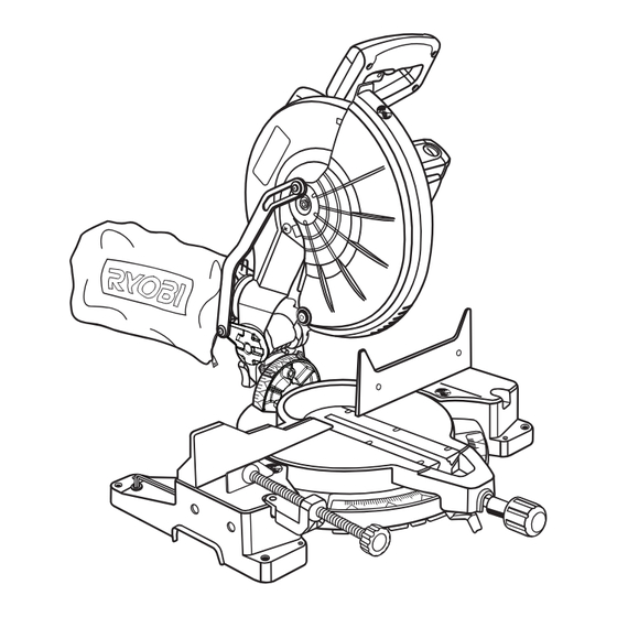
FEATURES KNOW yOUR COMPOUND MITER SAW carrYing See Figure 1. handLe “d” handLe The safe use of this product requires an understanding of the information on the tool and in this operator’s manual as well as a knowledge of the project you are attempting. Before use of this product, familiarize yourself with all operating features and safety rules. -
Page 11: Tools Needed
FEATURES POSITIVE STOPS ON MITER TABLE ELECTRIC BRAKE Positive stops have been provided at 0°, 15°, 22-1/2°, 31.62°, An electric brake has been provided to quickly stop blade and 45°. The 0°, 15°, 22-1/2°, 31.62°, and 45° positive stops rotation after the switch is released. have been provided on both the left and right side of the MITER FENCE miter table. -
Page 12: Loose Parts List
LOOSE PARTS LIST The following items are included with your compound miter saw: Miter Lock Handle Dust Bag Work Clamp Blade Wrench Operator’s Manual dust work cLaMp Miter Lock handLe bLade wrench Fig. 6 WARNING: The use of attachments or accessories not listed might be hazardous and could cause serious personal injury. -
Page 13: Assembly
ASSEMBLy UNPACKING WARNING: This product requires assembly. Do not attempt to modify this tool or create accessories Carefully lift saw from the carton by the carrying handle not recommended for use with this tool. Any such altera- and the saw base, and place it on a level work surface. tion or modification is misuse and could result in a hazard- NOTE: This tool is heavy. - Page 14 ASSEMBLy MITER LOCK HANDLE See Figure 8. To install the miter lock handle, place the threaded stud on the end of the miter lock handle into the threaded hole in the control arm under miter table. Turn clockwise to tighten. tighten DUST BAG See Figure 9.
- Page 15 ASSEMBLy TO INSTALL / REPLACE THE BLADE See Figures 11 - 12. WARNING: A 12 in. blade is the maximum blade capacity of the saw. Never use a blade that is too thick to allow outer blade washer to engage with the flats on the spindle. Larger blades will come in contact with the blade guards, while thicker blades will prevent the blade bolt from secur- ing the blade on the spindle.
- Page 16 ASSEMBLy NOTE: Many of the illustrations in this manual show only portions of the compound miter saw. This is intentional so Miter that we can clearly show points being made in the illustra- FraMing Fence sQuare tions. Never operate the saw without all guards securely Miter tabLe in place and in good operating condition.
- Page 17 ASSEMBLy socket head socket head screw(s) screw(s) Miter Fence bLade Fence FraMing Miter Miter Miter sQuare Lock Lock tabLe handLe pLate view oF bLade sQuare with Fence Fig. 17 Fig. 16 Miter Fence SQUARING THE BLADE TO THE FENCE See Figures 17 - 19. ...
-
Page 18: Assembly
ASSEMBLy SQUARING THE BLADE TO THE MITER TABLE beveL See Figures 20 - 23. Lock knob Unplug the saw. Pull the saw arm all the way down and engage the lock Miter pin to hold the saw arm in transport position. Fence ... -
Page 19: Operation
OPERATION CUTTING WITH yOUR COMPOUND WARNING: MITER SAW Do not allow familiarity with tools to make you care- less. Remember that a careless fraction of a second is WARNING: sufficient to inflict serious injury. When using a work clamp or C-clamp to secure your workpiece, clamp workpiece on one side of the blade WARNING: only. - Page 20 OPERATION Lift and hold the miter lock plate then rotate the miter table Miter cut until the pointer aligns with zero on the miter scale. Release the miter lock plate. NOTE: You can quickly locate 0°, 15°, 22-1/2°, left or right, 31.62°...
- Page 21 OPERATION Loosen the bevel lock knob and move the saw arm to coMpound Miter cut the left to the desired bevel angle. Bevel angles can be set from 0° to 45°. Align the indicator point for the desired angle. ...
- Page 22 OPERATION Place the workpiece flat on the miter table with one edge securely against the fence. If the board is warped, place the convex side against the fence. If the concave edge of a board is placed against the fence, the board could collapse on the blade at the end of the cut, jamming the blade.
-
Page 23: Cutting Compound Miters
OPERATION CUTTING COMPOUND MITERS To aid in making the correct settings, the compound angle setting chart below has been provided. Since compound cuts are the most difficult to accurately obtain, trial cuts should be made in scrap material, and much thought and planning made, prior to making the required cut. -
Page 24: Cutting Crown Molding
OPERATION CUTTING CROWN MOLDING When setting the bevel and miter angles for compound miters, remember that the settings are interdependent; changing This compound miter saw does an excellent job of cutting one angle changes the other angle as well. crown molding. In general, compound miter saws do a better Keep in mind that the angles for crown molding are very job of cutting crown molding than any other tool made. -
Page 25: Operation
OPERATION Bevel Angle Type of Cut Setting Left side, inside corner 1. Top edge of molding against fence 33.85° 2. Miter table set right 31.62° 3. Save left end of cut Right side, inside corner 1. Bottom edge of molding against fence 33.85°... -
Page 26: Adjustments
ADJUSTMENTS POSITIVE STOP ADJUSTMENTS WARNING: See Figure 35. NOTE: These adjustments were made at the factory and Before performing any adjustment, make sure the tool is normally do not require readjustment. unplugged from the power supply. Failure to heed this warning could result in serious personal injury. -
Page 27: Maintenance
MAINTENANCE WARNING: brush When servicing, use only identical replacement parts. Use of any other parts may create a hazard or cause brush product damage. asseMbLY brush WARNING: asseMbLY Always wear safety goggles or safety glasses with side shields during power tool operation or when blowing brush dust. - Page 28 When ordering repair parts, always give the following information: TS1553 • MODEL NUMBER • SERIAL NUMBER Ryobi is a registered trademark of Ryobi Limited used under license. ® ONE WORLD TECHNOLOGIES, INC. 1428 Pearman Dairy Road, Anderson, SC 29625 Phone 1-800-525-2579 www.ryobitools.com...
Need help?
Do you have a question about the TS1553 and is the answer not in the manual?
Questions and answers