Table of Contents
Advertisement
Quick Links
Advertisement
Table of Contents

Subscribe to Our Youtube Channel
Related Manuals for Avid Technology VENUE


Summary of Contents for Avid Technology VENUE
- Page 1 VENUE Profile Guide and VENUE Software 2.9 9322-62809-00 REV A 08/10...
- Page 2 Guide Part Number 9322-62809-00 REV A 08/10 Documentation Feedback At Avid, we are always looking for ways to improve our documentation. If you have comments, corrections, or suggestions regarding our documentation, email us at techpubs@avid.com.
-
Page 3: Table Of Contents
Unpacking and Assembling VENUE Profile ........ - Page 4 Assigning and Using VCAs ............... 86 VENUE Profile Guide...
- Page 5 VENUE System Information Export ........
- Page 6 Assigning Hardware Inserts to Channels ............167 VENUE Profile Guide...
- Page 7 Part V Shows Chapter 20. Shows and File Management ............171 Creating Shows .
- Page 8 VENUE Profile Systems: Output Signal Flow........
- Page 9 Connecting a Wireless Router or WAP to VENUE........
- Page 10 VENUE Profile Guide...
-
Page 11: Part I Overview And Installation
Part I: Overview and Installation... -
Page 13: Chapter 1. Introduction To Venue Profile
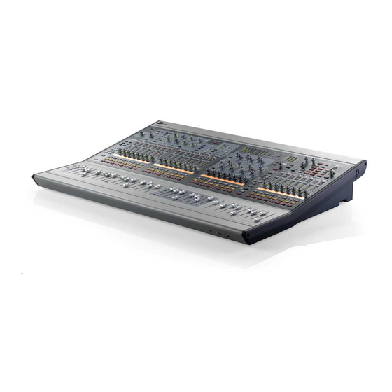
I/O scheme, powerful digital processing, and expansion options for integrated Pro Tools recording and artist-controlled monitor mixing. VENUE Profile Systems and Features The VENUE Profile console can be used with one Mix Rack, or with FOH Rack and Stage Rack units. Figure 1. VENUE Profile console Profile Console Control Features Console I/O •... - Page 14 • 100 BaseT Ethernet (ECx) port for remote control. FOH Rack houses the CPU, DSP, hard drive and CD-ROM drive that run the VENUE software on your VENUE system. System CPU, DSP, and System Drives software is installed at the factory. The CD-ROM drive lets you...
-
Page 15: System Components
Stage Racks are used with an FOH Rack, and provide all stage The following components must be purchased separately: audio I/O for VENUE Profile systems. Up to two Stage Racks • Video Display (15-inch or greater flat-panel VGA display can be used simultaneously, supporting up to 96 total inputs. - Page 16 Personal Q The Personal Q (PQ) monitoring system lets per- VENUE MADI Card This option card lets you send or receive up formers adjust their monitor mix being sent from VENUE us- to 64 channels of MADI digital audio. The VENUE MADI card ing a PQ Controller unit.
-
Page 17: Operational Requirements
Cleaning and Maintenance VENUE Profile Systems Use a dry cloth to clean the VENUE Profile top surface when Connection between the FOH Rack and the Stage Rack is made needed. Do not apply any cleaning solutions, spray cleaners, with the Digital Snake cable (not included). Cables can be pur- or abrasives to the surface. -
Page 18: System Requirements And Compatibility
Conventions Used in This Guide Compatibility All of our guides use the following conventions to indicate menu choices and key commands: Avid can only assure compatibility and provide support for hardware and software it has tested and approved. Convention Action For complete system requirements and a list of qualified com- File >... -
Page 19: About Www.avid.com
Devel- opment Partners and their plug-ins, applications, and hard- ware. News and Events Get the latest news from Avid or sign up for a product demo. Pro Tools Accelerated Videos Watch the series of free tutorial videos. - Page 20 VENUE Profile Guide...
-
Page 21: Chapter 2. Configuring And Connecting Profile
Chapter 2: Configuring and Connecting Profile The chapter shows how to connect the components of a To assemble the Video Monitor Mount: VENUE Mix Rack and VENUE Profile system. Remove the Video Monitor Mount components from their packaging. Unpacking and Assembling... - Page 22 Tighten all screws to secure the monitor in its new position. the mount with the front panel USB and Headphone ports so they remain accessible. Tighten the lock nuts to secure the assembled Trackball Mount to the console. VENUE Profile Guide...
- Page 23 Using the Trackball Mount The Trackball Mount can be removed and set up quickly. Always disconnect USB and headphones from the front panel before removing or attaching the Trackball Mount. To remove the Trackball Mount: Holding the Trackball Mount in one hand, loosen the lock nuts that secure it to the front of the console.
-
Page 24: Connections For Venue Mix Rack Systems
Connections for VENUE Mix Rack Systems This section describes system and audio connections for VENUE Mix Rack systems. (For VENUE Profile systems, see “Connections for VENUE Profile Systems” on page 17). To connect the Profile console to a Mix Rack: Connect one end of the FOH Link cable to the FOH Link port on the back panel of the Profile console. - Page 25 Stage Inputs 1–48 (Analog Mic/Line XLR Inputs) The Stage Input section provides 48 channels of analog mic/line inputs (XLR), to connect stage input sources. Use a standard an- alog snake cable to run lines from the stage to the Mix Rack (analog snake cable not included). Then connect the snake to Stage inputs 1–48.
- Page 26 The FOH Link port connects the Profile console to the system rack (Mix Rack, or FOH Rack in conjunction with one or more Stage Racks). Word Clock I/O The Word Clock In and Word Clock Out ports let you inte- grate external digital devices with Mix Rack. VENUE Profile Guide...
-
Page 27: Connections For Venue Profile Systems
Connections for VENUE Profile Systems This section describes system and audio connections for FOH Rack and Stage Rack systems. (For VENUE Mix Rack systems, see “Connections for VENUE Mix Rack Systems” on page 14). VENUE Profile FOH Link Cable FOH Rack (Front) -
Page 28: Connecting The Stage Rack To The Foh Rack
Connect the return snake to the Stage 1 Out port on the FOH Rack, and to the Stage 1 In port on the Stage Rack. The connectors on Avid’s Digital Snake cable are color coded, so that the white cable connects to the white-outlined ports. - Page 29 Connecting a Second Stage Rack If a second Stage Rack is used, an additional Snake Card must be installed in the FOH Rack. See the Snake Card Guide for more information. To connect a second Stage Rack: Using a BNC cable (included with the additional Snake card), connect the Word Clock Out port on the first Snake card to the Word Clock In port on the second Snake card.
-
Page 30: Audio Connections
SRO Card. Digital I/O If your Stage Rack includes a digital I/O option, see “Digital In- puts and Sample Rate Conversion” on page 24. VENUE Profile Guide... - Page 31 (AES/EBU and S/PDIF Connectors) Switch the 2-Track digital I/O between AES/EBU and S/PDIF If you are integrating digital devices with your VENUE system, by moving the 2-Track Digital Format selector switch to the make the necessary Word clock connections and settings. For corresponding position.
-
Page 32: Profile Console Connections
Adjust talkback send level by pressing the Talkback switch VENUE Profile provides USB ports on the top panel (near the in the Talkback/Osc section and turning the level knob. meters) and on the back panel. Use these ports to connect iLok Smart Keys, USB flash disks or other compatible USB devices. -
Page 33: Powering Up The System
• Mix Rack VENUE Profile console Setting the System Clock When you first work with a VENUE system, make sure the sys- tem clock time, date and time zone are set appropriately. The system clock setting can affect data synchronization with por- table storage devices. -
Page 34: Enabling A Second Stage Rack
The types of digital I/O and connectivity available varies de- pending on your system components and their configuration: Mix Rack The VENUE Mix Rack provides a pair of digital (AES) 2-Track inputs and outputs. The Mix Rack can also be ex-... - Page 35 Click the channel’s SRC OFF button until it turns off. DSI card AES (or ADAT) Auto-Detecting The DSI card (or other VENUE digital card) automatically de- tects whether an external device connected to a DSI input is Set device to slave to synchronized to the VENUE system. Here, “synchronized”...
- Page 36 External digital device DSI card AES (or ADAT) Set device to slave to incoming Word Clock FOH Rack House clock source Word Clock In Using a distributed house (master) to clock a VENUE system and an external device VENUE Profile Guide...
-
Page 37: Part Ii System Description
Part II: System Description... -
Page 39: Chapter 3. Venue Profile Control Overview
Profile provides 24 bankable input channel strips in Input Channel sections, an Assignable Channel Section (ACS), eight bankable output channel strips plus a Mains fader in the Output Masters section, as well as global controls and comprehensive metering. Chapter 3: VENUE Profile Control Overview 29... -
Page 40: Input Channels And Faders
Auto Safe Mode If the Safe LED is lit, the channel will not re- spond to Snapshot-driven changes. If the LED is off, that channel will respond to any applicable changes driven by Snapshots (subject to the current Recall Safe settings, if Recall Safe is enabled). VENUE Profile Guide... - Page 41 For LED scales, see “Gate Status LED” on page 115. ments. A flashing LED indicates that the channel is assigned to the corresponding Mute Group (1–8). Stereo Pan LED This LED indicates when the channel is assigned to a stereo Groups bus. Chapter 3: VENUE Profile Control Overview 31...
- Page 42 When the send is on, all LEDs light in a clockwise se- holding the encoder initiates Gain Guess, in which the quence from the lower left to the send level. VENUE system automatically sets a nominal input gain level based on the incoming signal. VENUE Profile Guide...
- Page 43 Flip to Faders Aux (n) Level and Pan (stereo-linked sends 25–48, and so on. only) FX Returns Banks FX Return channels 1–8 to Input faders 1–8, or FX Returns 9–16 to Input faders 9–16. Chapter 3: VENUE Profile Control Overview 33...
-
Page 44: Assignable Channel Section
The Bus Assigns switches are the primary routing controls for the currently selected channel, letting you bus it directly to the Mains (L–R) bus or to any other mono or stereo group. L–R C/Mono Group 1–8 Stereo Pan Bus assign switches VENUE Profile Guide... - Page 45 The Selected Channel display section include two 10-segment Selected Channel meters, a 6-character LCD display and LEDS for Status and Solo state. EQ section and controls See Chapter 17, “EQ.” LCD Display Meters LEDs Selected Channel meters, displays and LEDs Chapter 3: VENUE Profile Control Overview 35...
-
Page 46: Output Masters
Output encoders select and adjust plug-ins. levels. Groups Assigns the Output Faders to Group levels. When in Variable Groups mode, this switch assigns the Output Faders to control Variable Groups. VCAs Assigns the Output Faders to VCAs. VENUE Profile Guide... -
Page 47: Master And Global Controls
Chapter 22, “Events.” Console Mode The Config Mode switch toggles the system between Config Cancel and Show modes. This switch cancels the current operation, such as Multi-Select or Multi-Assign modes. Console Mode Chapter 3: VENUE Profile Control Overview 37... -
Page 48: Meters
Mains The Mains meters provide constant level indication of the house (Mains) output. For more information, see Chapter 13, “Metering.” Top panel USB port and status LEDs For more information, see Chapter 28, “Troubleshooting.” VENUE Profile Guide... -
Page 49: Chapter 4. Basic Commands And Modes
Chapter 4: Basic Commands and Modes Tool Tips Control Overview With the mouse or trackball, place the cursor over a screen Most features and controls that are used during a performance item to see a brief explanation in the banner display. are available from both the console and on-screen. -
Page 50: Config Mode And Show Mode
• Perform system tests and diagnostics You can add your own custom images to display in place of the default VENUE logo. See “Customizing the System Some Config mode operations interrupt audio throughput. Lock Display” on page 41 for information. -
Page 51: Global Modifier Switches
Customizing the System Lock Display Multi-Select Switch You can manually add one or more custom images to display during System Lock, rather than the default VENUE logo back- The Multi-Select (Shift) switch lets you select multiple Input ground. Channels and then apply an action to all selected channels. -
Page 52: Software Screen Pages And Tabs
Double-press the Fine switch. The switch LED lights. Viewing pages Select or adjust one or more channels, parameters, or pro- cessors. Press the Fine switch again to exit latching mode. User The User switch is reserved for future use. VENUE Profile Guide... - Page 53 Overview of Software Pages Filing The software screen provides the following pages and tabs. Load, save, and transfer shows and presets, and access the con- sole History. Inputs Select, name, configure, and adjust parameters for input chan- nels and FX Returns. Filing (Load tab) See Chapter 20, “Shows and File Management.”...
- Page 54 Configure system, routing and metering options, set interac- tion, hardware and general preferences, install plug-ins, and access the Events window. Patchbay (Outputs tab) Options page (System tab for VENUE Mix Rack system shown) See Chapter 12, “Patchbay.” Plug-Ins See Chapter 6, “Options.”...
-
Page 55: Chapter 5. Navigating And Selecting Channels
The FX Returns switches bank FX Return channels 1–8 or 9–16 Returns to input faders 1–8 or 9–16, respectively. Many VENUE configurations utilize more physical inputs When only one FX Return bank is selected, other input faders than input faders. To navigate to channels beyond the num- remain banked on their current input channels. - Page 56 Show file. Enabling and Using Bank Safe Mode Bank Safe mode can be enabled on-screen from the Options > Interaction page. To enable Bank Safe mode on-screen: Go to the Options > Interaction page. VENUE Profile Guide...
- Page 57 Click the channel Safe buttons on-screen, located at the top • Splitting a stereo strip(s) of each input channel strip. • Opening a Show file that was saved on a VENUE system that used a different console. Safe buttons Priority for Replacing Bank Safe Assignments...
-
Page 58: Banking The Output Section
To select multiple channels on-screen: Press and hold the Multi-Select switch (or hold Shift on the Each VENUE channel strip has a channel Select switch. The keyboard) and click the fader strips on-screen. Select switch targets that channel for routing or processing as- signment. -
Page 59: Targeting Plug-In Inserts
– or – Channel Numbers and Names • Click Cancel in the on-screen Multi-Assign dialog box. VENUE SC48 channel numbers are “absolute” channel num- See Chapter 8, “Outputs and Output Routing.” bers. Renaming changes the displayed name associated with each channel, but the absolute channel number remains fixed. -
Page 60: Screen Controls
Any offset between the faders is maintained until at least one of the faders is minimized (moved to –INF) or maximized (set to +12 dB). Adjusting a parameter value by dragging over its text box Selected channels Dragging multiple faders on-screen VENUE Profile Guide... -
Page 61: Screen Shortcuts
To copy and paste channel settings on-screen: Screen Shortcuts Do one of the following: The on-screen Fader display provides the following right-click • Right-click on a channel fader in the fader display across shortcuts. the lower half of the screen and choose Copy. –... - Page 62 A blank strip can be right-clicked to reveal its context menu. channel, or splits a selected stereo channel into two mono channels. VENUE must be in Config mode to change the ste- reo status of a channel. Move Selected Strip Moves a selected strip from its current position to a new loca- tion.
- Page 63 Automatically Inserting Blank Strips using Make Stereo depending on the current system configuration and the num- VENUE automatically creates blank strips when you use the ber of stereo channels used in the configuration. This number Make Stereo command in order to preserve the current chan- can be calculated as: nel layout.
-
Page 64: Input Channel Presets
Presets can only be loaded into a single channel at a time. put Channel Presets. Input Channel Presets can be previewed, recalled and transferred just like other VENUE preset files, let- Click the Channel Presets icon. ting you quickly configure channels from among a library of If necessary, click the Folders icon and select the appropriate favorite setups. - Page 65 Channel Presets to a USB key disk or other storage device for backup and transfer to other systems. Input Channel Presets are supported on all systems running VENUE software 2.5 or later, including the Standalone soft- ware. For more information, see Chapter 20, “Shows and File Management.”...
- Page 66 VENUE Profile Guide...
-
Page 67: Chapter 6. Options
Mains and Aux/Group busses, • The Devices screen provides status, diagnostics, and op- reset the system (clear console), and quit (shut down VENUE). tions for hardware components. This chapter shows you how to manage the most important... - Page 68 This setting enables L–C–R mode, which lets you mix in channels. “3-across-the-front” mode. • You can configure a VENUE Mix Rack system to use 16, Changing the Main Bus mode will restart the system soft- 24, 32, 48, or 64 input processing channels.
-
Page 69: Devices
Simulating a VENUE Configuration with the Standalone Software With the VENUE Standalone software, you can use the De- vices page to simulate a VENUE system of any size for pur- poses of preparing shows and training. See “Simulating a VENUE Configuration” on page 224. -
Page 70: Other Options And Settings
Link option for the corresponding pair. the Mains fader. • Specify the panning for channels routed to Aux bus pairs with the Follows Channel Pan option. • Click to select the pickoff point for each bus (Pre-EQ, Pre-Mute, or Pre-Fader). VENUE Profile Guide... - Page 71 “Matrix and Personal Q Mixers.” Off No Delay Compensation is applied. Panning/Center Divergence Mix Only VENUE automatically compensates for delays in- The Panning section provides control over center channel di- curred by the use of Groups routed to the Mains busses.
- Page 72 MIDI channel. For more information, see Chapter 21, “Snapshots.” MIDI Snapshot Output Safe Safes (shuts off) VENUE MIDI out- put when snapshots are recalled. This does not affect sending of Bank Select and Program Change commands with the Snap- The options in the PRE section let you specify which parame- shots Send on Channel option.
- Page 73 Misc Routing Osc, 2-Track and Talkback The Miscellaneous page provides utility and other settings. Use the Patchbay to assign the Oscillator, 2-Track inputs, or Talkback input to an Input or FX Return fader. You can use the on-screen Route buttons to route oscillator, 2-track and talkback signals to outputs.
- Page 74 Targeting Changes View Mode The Targeting Changes View Mode option updates the on-screen display to show the page for the channel targeted. When this option is deselected, the on-screen display does not update when a channel is targeted. VENUE Profile Guide...
- Page 75 Network Settings These settings let you configure ECx Ether- Ballistics This option lets you choose RMS or Peak ballistics net Control to remotely control VENUE over a wireless Ether- for the control surface and on-screen meters. net network.
- Page 76 Options > Events page Plug-Ins The Plug-Ins tab of the Options page is used to install plug-ins on the VENUE system. The Plug-Ins tab is available on com- plete VENUE systems only. It is not available in the Stand- alone software.
-
Page 77: Part Iii Signal Routing
P a r tI I I : S i g n a l R o u t i n g... -
Page 79: Chapter 7. Inputs And Input Routing
Configuring FX Returns • Adjust input channel parameters VENUE Mix Rack and Profile systems provide up to 16 stereo FX returns. You can choose to use either 8 or 16; choosing fewer FX Returns leaves more DSP available for plug-ins. For Configuring Inputs details, see “Configuring FX Returns”... -
Page 80: Assigning Input Sources To Channels
2-Track sources to input channels (see “Routing the Oscilla- grid and type a name; press Tab on the keyboard to go to the tor” on page 128). next channel and Shift+Tab to go to the previous channel. VENUE Profile Guide... -
Page 81: Routing Input Channels
Routing Channels to Aux Sends Routing Input Channels Input channels and FX Returns can be routed to Aux sends us- Input channels and FX Returns can be routed to the Mains, ing the input encoders, using the ACS, or on-screen. Groups/Var Groups, Auxes, Matrix mixers and PQ busses. -
Page 82: Using Built-In Dynamics And Eq
Configuring Aux Busses (Aux Sends) – or – VENUE systems can be configured to have 8 or 16 Aux busses as part of the overall Aux/Group bus configuration. Mono Aux Select another VCA to confirm the current assignment but re- buses can be linked in odd/even pairs to function in stereo (see main in Multi Assign mode for the newly targeted VCA. -
Page 83: Using Inserts On Channels
Compressor/Limiter To adjust Expander/Gate controls from the ACS: Target a channel by pressing its Select switch. To engage the built-in Compressor/Limiter on the selected Press the Select switch next to the Exp/Gate In switch and channel: meter in the ACS Dynamics section. The switch lights to indi- Press the Comp/Lim In switch in the ACS Dynamics sec- ... - Page 84 Assigning Hardware Inserts to Inputs You can assign hardware inserts to Input channels and FX Re- turns directly from the Inputs page or from the Patchbay. Click to set HW Insert location Setting a hardware insert location in the Inputs page VENUE Profile Guide...
-
Page 85: Adjusting Input Controls
Activating and Bypassing Inserts Setting Input Gain After hardware and plug-in inserts are assigned, they can be Gain can be controlled from individual channel strips or from the ACS section. activated and bypassed from the from the ACS section or the corresponding Input page controls. - Page 86 L–R. Width controls are not available on mono channels. switch lights when the pad is applied to the Stage input. The Gain Guess feature turns the Pad on or off as needed to accommodate incoming signal level VENUE Profile Guide...
- Page 87 Input Polarity (Phase) Invert Channel Solo The polarity of any input channel or FX return signal can be Three Solo modes are available: Solo In Place (SIP), Pre-Fader inverted. With stereo channels, only the left channel is in- Listen (PFL), and After-Fader Listen (AFL), and several options verted.
-
Page 88: Using Input Direct
Go to the Inputs page. Click the Input Direct button in the Config section of the In- puts page for the selected channel. The button flashes to indi- cate Input Direct mode is active. Input Direct Input Direct button VENUE Profile Guide... -
Page 89: Chapter 8. Outputs And Output Routing
Chapter 8: Outputs and Output Routing This chapter shows how to do the following: Click Edit. • Configure and name Mains, outputs and busses • Assign outputs and busses to hardware outputs in the Patchbay • Route outputs to Mains, Groups, Aux Sends, and Matrix mixers •... -
Page 90: Assigning Busses To Hardware Outputs
Go to the Patchbay page and click the Outputs tab. Selecting a bus configuration To the left of the channel grid, click the Mains, PQ, Mtx (Ma- Click Apply. The system restarts with the new bus configura- trix), Aux or Grp (Groups) tab. tion. VENUE Profile Guide... -
Page 91: Routing Group Outputs To The Mains Busses
Click in the channel grid to assign a bus or Matrix/PQ mixer In the Bus Assigns section, press the L–R (left and right) or output (listed on the left) to a hardware output (listed across C/Mono (center/mono) switch so that it is lit. the top). -
Page 92: Using Inserts On Output Busses
In the Inserts section of the Outputs page, do one of the fol- vated. (Hardware insets cannot be bypassed from the Profile lowing: console; use the on-screen control instead.) • Click the Hardware Insert pop-up menu and choose an insert destination directly from the menu. – or – VENUE Profile Guide... -
Page 93: Adjusting Output Controls
Inserting the Built-In Graphic EQs on Output Busses A built-in 31-band Graphic EQ can be inserted on any of the Output Fader Output bus types. A maximum of 24 Graphic EQs are avail- assignment able, depending on the how they are configured. For more in- switches formation on configuring and using Graphic EQs, see “Graphic EQ for Outputs”... -
Page 94: Adjusting Main Bus Controls
Left, Right, or Center/Mono out- put strips to assign control of the corresponding busses to the Mains Fader. Press the Mute switch to toggle the mute status of the as- Fader signed busses. Mains Fader and controls in the Output section VENUE Profile Guide... -
Page 95: Direct Outputs
Main Bus Automatic Delay Compensation Select the pickoff point for the Direct Output by clicking the VENUE systems automatically compensate for delays incurred letter to the right of the channel or bus name and choosing by the use of Groups and insertion of plug-ins in the signal from the pop-up menu. -
Page 96: Matrix Mixers
See Chapter 11, “Matrix and Personal Q Mixers.” or output channels you want to assign to the VCA. Press the flashing Multi-Assign switch to confirm the assign- ment, or press the Cancel switch to cancel the assignment. VENUE Profile Guide... - Page 97 On-Screen VCA Indication Displays settings in the Options > Interaction page. VENUE displays effective gain as a second, transparent fader To turn channel VCA indication off or on: cap on-screen in the fader displays of both the Inputs and Out- Go to the Options >...
- Page 98 • Press the FX Returns 1-8 switch. • Press a GEQ switch. • In the on-screen dialog, click Exit VCA Spill. Selecting Other VCAs While Spilled Selecting another VCA while spill mode is active automati- cally spills that VCA. VENUE Profile Guide...
-
Page 99: Chapter 9. Groups
Chapter 9: Groups This chapter shows how to do the following: To route channels to any number of Group busses: • Configure Group busses Target one or more channels. • Route Groups In the Bus Assigns section, press any of the Group switches •... -
Page 100: Managing Group Bus Assignments
Un- used channel strips are left blank and inactive. If the Group contains more than 16 members only the first 16 members are shown. VENUE Profile Guide... - Page 101 Click the Input Assign pop-up menu at the bottom of the Viewing Group Bus Assignments On-Screen Members list, choose Replace With Mix From, then choose the When a Group bus channel is targeted on-screen, its members Group whose assignments you want to copy to the currently are shown in a list on the right side of the Outputs page.
-
Page 102: Group Bus Signal Flow Options
Group pan to the Output encoders. contribution to the odd and even sides of the bus pair. Turn a rotary encoder to adjust the pan for the correspond- ing mono Group. VENUE Profile Guide... -
Page 103: Simple And Expert Operational Modes
To control stereo Group output balance and width: To set the link status of individual mono Group busses on a channel (Expert Mode only): Press the Pan switch in the Output encoder section. Make sure Stereo Group Panning is set to Expert Mode. Turn a rotary encoder to adjust the balance for the corre- Select an input channel or FX return whose signal you want sponding stereo Group. - Page 104 VENUE Profile Guide...
-
Page 105: Chapter 10. Aux Sends And Variable Groups
Chapter 10: Aux Sends and Variable Groups This chapter explains the following Aux Sends operations: Click Edit. • Configuring Aux Send busses • Routing to Aux Sends • Adjusting Aux Send parameters • Managing Auxes Bus Pair Links Configuring Aux and Variable Group Busses Up to 16 Aux busses are available. -
Page 106: Routing Inputs To Aux Busses
Activating Pre pickoff for an Aux Send (Inputs page shown) • Press the Flip to Faders switch, then adjust the channel When the Pre button is lit, the selected Pre pickoff point is fader. used. When the Pre button is off, the pickoff point is Post-Fader. VENUE Profile Guide... -
Page 107: Routing Aux Busses To Outputs And Plug-Ins
To route channels to Aux Sends busses using the ACS: Routing Aux Busses to Outputs and Do either of the following: Plug-Ins • To select a single channel, press its Select switch. Aux and Var Group busses can be routed to hardware outputs •... -
Page 108: Adjusting Aux Send Controls
To set the Aux Send pan to follow Channel pan: Go to the Options page and click the Busses tab. On any linked bus pairs, select the Follows Channel Pan op- tion. This setting is applied globally to the corresponding Aux Send. VENUE Profile Guide... -
Page 109: Managing Aux Bus Assignments
Copying Assignments Between Busses Managing Aux Bus Assignments You can copy the current input assignments from one Aux or Variable Group bus (or Mains) to another bus of either type. If Viewing Aux and Variable Group Bus the busses are linked, assignments can be copied from other Assignments linked busses. - Page 110 VENUE Profile Guide...
-
Page 111: Chapter 11. Matrix And Personal Q Mixers
Chapter 11: Matrix and Personal Q Mixers The Outputs section offers 8 mono Matrix mixers and 8 stereo Personal Q (PQ) mixers for setting up alternate mixes, fill and delay feeds, and cue, monitor or press mixes. Matrix Mixers Each of the 8 available Matrix mixers can receive up to 12 channels of input. Input sources can be any combination of Auxes, Groups or Mains busses, or any of the eight available Matrix User Sends. -
Page 112: Personal Q Mixers
With the optional Personal Q Controller system, performers can adjust the controls in the Personal Q mixer from a remote location. See the VENUE Personal Q Guide for details. If no PQ Controllers are used, the PQ mixers are still avail- able for use as stereo Matrix mixers controllable from the console. -
Page 113: Configuring Matrix And Pq Mixers
To stereo link Matrixes: Configuring Matrix and PQ Mixers Put the system into Config mode. The 12 Inputs for each Matrix and PQ mixer can be any com- Go to the Options > Busses page. bination of these 35 potential sources: In the Matrix section, click Edit. - Page 114 Toggling one channel from Off to On results in both channels switching On; toggling one of the linked channels from On to Off results in both channels switching Off. VENUE Profile Guide...
- Page 115 For any assigned User Inputs, click the Pickoff pop-up menu Configuring User Inputs and choose the desired pickoff for that User Input source. You can assign up to eight User Inputs to be available globally Choices include Top of Channel, Insert Return, and to the Matrix mixers and, separately, up to eight User Inputs Pre/Post-Fader (for Input Channels) or Top of FX Return and to be available globally to the PQ mixers.
-
Page 116: Adjusting Matrix And Pq Mixer Input Controls
Press the Pan switch located below the Prev Page and Next Page switches. Adjust the Output Encoder 1–8 to adjust pan on Matrix in- puts 1–8. To access inputs 9–12 for the current mixer, press the Next Page switch. VENUE Profile Guide... -
Page 117: Adjusting Matrix And Pq Mixer Output Controls
Delay Compensation with Matrix and Adjusting Matrix and PQ Mixer Output PQ Mixers Controls VENUE automatically compensates for the delay offsets that can arise when combining different signal paths within a Ma- Matrix and PQ Mixer Output Levels trix or PQ mixer. -
Page 118: Working With A Pq Controller
Working with a PQ Controller When an optional Personal Q remote control system is con- nected to a VENUE system, it can be used to adjust the con- trols in the Personal Q mixers from a remote location. For complete instructions on connecting and using PQ Con- trollers, refer to the Personal Q Controller Guide, included with the PQ Controller system. -
Page 119: Chapter 12. Patchbay
Chapter 12: Patchbay The main tools and sections of the Patchbay screen are the Accessing the Patchbay following: To show the Patchbay screen: Tabs Press the Patchbay switch, located in the View Modes sec- The Patchbay is navigated using the following tabs. tion, or click the Patchbay tab on-screen. - Page 120 The Patching Grid shows hardware I/O across the top, and assignments to unavailable hardware I/O. VENUE channels down the left side. The available channel The VENUE Standalone software provides additional display tabs and choices are determined by the currently selected I/O options for hardware I/O (including unavailable I/O).
-
Page 121: Navigating The Patchbay
Avoid giving channels names that begin with numbers dif- ferent from the absolute channel number. When you type a number, VENUE navigates to absolute channel numbers re- Scrolling the Patching Grid by right-clicking and dragging gardless of the channel name. - Page 122 Click the Inputs tab and navigate to the input channel being fed from the DSI input. On VENUE Mix Rack systems, choosing the 64 channel set- Click the ADAT button on-screen, in the channel Input con- ting gives you additional input processing channels beyond trols section.
-
Page 123: Warning When Stealing Inputs Or Outputs In The Patchbay
Go to the Options > System page. on-screen). Click the Info button. Export VENUE System Information button in Options > System Do any of the following: • If you have more than one USB key disk connected, make sure the correct USB key disk is selected. If it is not, click... -
Page 124: Patch List Export
System Configuration Lists information found on the Options tents include the following: > System tab. VENUE Patch List DSP Usage Lists the processes assigned to each DSP of each Mix Engine card. Information is sub-divided by Mix Engine as Show Name, file path, date and time of most recently loaded displayed on the Options >... -
Page 125: Chapter 13. Metering
Chapter 13: Metering VENUE provides signal metering on the channels, in the me- Compressor/Limiter Gain Reduction Meter tering section, and on-screen. The LEDs in the Compressor/Limiter meter show the amount of gain reduction being applied to the input channel by the... -
Page 126: Acs Input And Dynamics Meters
0 dB Green 12 dB Green -3 dB Green 21 dB Green -9 dB Green 36 dB Yellow -15 dB Green 6 (left) 60 dB Yellow -21 dB Green -30 dB Green 10 (bottom) -60 dB Green VENUE Profile Guide... -
Page 127: Metering Section
Selecting Output Meter Display Metering Section To select an output type for metering: The Metering section includes Bus and Main Outputs meters. Press the Select switch in the metering section to cycle through available choices (Auto, Aux 1–8, Aux 9–16, Personal Qs, Matrixes or Groups). -
Page 128: Metering Options
When Key Listen is activated, the left and right channels of the Solo bus are metered on the Selected Channel meters, VENUE meter clip indicators are proximity warnings that pre-Solo Trim control. show when an input or output signal reaches or exceeds the configured Clip Margin. -
Page 129: Chapter 14. Solo And Monitor Busses
Chapter 14: Solo and Monitor Busses Solo Bus Modes Selecting a Solo Mode Three Solo modes are offered: Pre-Fader Listen (PFL), The Solo mode can be selected from the Solo/PFL section or After-Fader Listen (AFL) and Solo In Place (SIP). on-screen. -
Page 130: Solo Operation Options
Auto Cancel Off, Input Priority Off Solos are additive, and so- loed inputs and outputs are heard together Auto Cancel Off, Input Priority On Solos are additive, and so- loed inputs temporarily replace soloed outputs. VENUE Profile Guide... -
Page 131: Solo Bus Operation
Soloing VCAs Solo Bus Operation When you solo a VCA, its member channels are soloed. If the VCA members include a combination of input and output Soloing Channels channels, their solo status follows any Solo switch options. See “Solo Operation Options” on page 120. Solo operation depends on the type of channel being soloed, and on any selected Solo switch options. -
Page 132: Monitor Bus Operation
2-Track return with- out having to disable Mix to Monitors. Assigning monitor output to a bus-fed plug-in Mix to Monitors The Mains mix (the signal present on the Mains busses) can be sent to the Monitor bus. VENUE Profile Guide... - Page 133 The following diagrams show the signal flow for PFL and AFL Sending the Main Mix to the Monitor Bus modes. Monitor Output from an L-C-R Main Mix Level Trim (PFL) The stereo Mix to Monitors signal is derived from the L–C–R Input Channel Main mix by adding a –3 dB signal from the Center channel to Solos (PFL)
- Page 134 You can set up an Event to toggle Cue on Mains on or off. See Chapter 22, “Events.” While Cue on Mains is enabled, the Mains busses remain available on-screen, and can be targeted to the ACS. VENUE Profile Guide...
-
Page 135: Talkback, 2-Track And Oscillator Controls
Talkback, 2-Track and Oscillator Controls Talkback Mic You can assign Talkback microphone input, 2-Track source in- connector puts, and the built-in Oscillator to any Input Channel or FX Return. Talkback, 2-Track, and built-in Oscillator output can Talkback be routed to any output busses. switch Level control 2-Track... - Page 136 To the left of the channel grid, click the Channels tab or the • AR (Analog Right) FX Returns tab. • DL (Digital Left) At the top of the channel grid, click the FOH tab. • DR (Digital Right) VENUE Profile Guide...
- Page 137 Activating 2-Track Input and Setting Level Routing to the 2-Track Outputs You can route any output bus or Direct Output to the 2-Track To feed 2-Track input to the Monitor and Mains busses: outputs. Go to the Options > Misc screen. To route any output bus to the 2-Track outputs: In the 2-Track section, click the Input Fed to Monitors and Masters pop-up and select Analog 2-Track or Digital 2-Track.
-
Page 138: Routing The Oscillator
If you select Variable Sine, you can set the sine wave fre- quency with the on-screen frequency control (directly to the right of the Signal pop-up). Click the on-screen In button in the Oscillator section. Set oscillator level by slowly raising the on-screen Level en- coder. VENUE Profile Guide... -
Page 139: Chapter 15. Muting And Mute Groups
Chapter 15: Muting and Mute Groups Muting Mute Groups Channels can be muted in three ways: explicitly (lit solid), Channels can be assigned to any of the 8 available Mute with the channel mute switch; implicitly (flashing), as a result Groups. - Page 140 Mute Groups, VCAs and Explicit Mutes Channels can be muted in three ways: Explicitly Using the channel Mute switch. Implicitly As a member of a Mute Group or VCA. – and – Implicitly As a result of another channel being soloed. VENUE Profile Guide...
-
Page 141: Function Switches
Press a flashing Mute switch to explicitly unmute the chan- Function Switches nel. Its Mute switch is now unlit. VENUE Profile provides 8 Function switches (F keys). Press the same (now unlit) Mute switch again to explicitly mute the channel. Its Mute switch is now lit solid. - Page 142 VENUE Profile Guide...
-
Page 143: Part Iv Processing
Part IV: Processing... -
Page 145: Chapter 16. Dynamics
Chapter 16: Dynamics VENUE Mix Rack and Profile systems offer the following dy- Built-In Compressor/Limiter namics features: • A built-in Compressor/Limiter and Expander/Gate is One built-in Compressor/Limiter (Comp/Lim) is available on available on each input channel. each input channel. The Comp/Lim defaults to compression, •... -
Page 146: Built-In Expander/Gate
Attack Increases or decreases the attack time for the Exp/Gate. Adjusting Dynamics Gate Hold Increases or decreases the time the gate holds. The VENUE Profile console provides Dynamics controls in in- put channel strips, the ACS, and on-screen. Release Increases or decreases the release time for the Exp/Gate. - Page 147 To adjust Threshold from an input strip: Software Screen Dynamics Controls Press an Encoder Assign switch (Comp/Lim, or Exp/Gate). The software screen lets you adjust built-in or plug-in dynam- ics on-screen, with simultaneous access to Comp/Lim and Rotate a channel encoder to adjust Threshold. Exp/Gate parameters (including their side-chain settings).
-
Page 148: Channel Modes Affecting Dynamics
• If the plug-in does not map to the ACS, press the Insert Mode switch in the Output section. Use the Output en- coders to adjust parameters; use the Previous Page and Next page switches to access other parameters. VENUE Profile Guide... -
Page 149: Dynamics Settings And Presets
Click the Comp/Lim or Exp/Gate Presets icon on-screen. Dynamics Settings and Presets Presets Comp/Lim Built-in Dynamics settings can be copied and pasted between channels. Settings can also be stored, loaded, and transferred as dynamics Presets. Presets Exp/Gate Copying and Pasting Dynamics Settings To copy and paste dynamics settings: Built-in dynamics Presets buttons Right-click anywhere in the Comp/Lim or Exp/Gate areas of... - Page 150 Key Listen on a Dynamics plug-in does not route the signal the Key signal is sourced. The top of channel pickoff can be to the Solo bus, but to the plug-in output. Use caution. as much as 18 dB louder than other pickoff points and sources. VENUE Profile Guide...
- Page 151 Chapter 16: Dynamics 141...
- Page 152 VENUE Profile Guide...
-
Page 153: Chapter 17. Eq
Chapter 17: EQ The following EQ features are available: Built-In EQ Parameters • A built-in EQ is available on each input channel and FX return. • Graphic EQs are available for use on output channels. • EQ plug-ins can be used on input and output channels. Each input channel provides a fourth-order high-pass filter •... -
Page 154: Adjusting Eq
EQ with variable Q. When in Shelf mode, the Hi module is a high-shelf EQ, and the Lo module is a low-shelf EQ. For in- In/Out structions on configuring these bands for Bell or Shelf mode, EQ controls in the ACS see “Adjusting EQ” on page 144. VENUE Profile Guide... - Page 155 To adjust EQ parameters from the ACS: Software Screen EQ Controls Target a channel by pressing its Select switch. You can adjust the built-in EQ using dedicated on-screen but- tons for band in/out and bell/shelf toggling. Press the EQ In switch to enable built-in EQ on that chan- nel.
-
Page 156: Channel Modes Affecting Eq
Insert Mode switch in the Output section. Use the Output encoders to adjust parameters; use the Previous Page and Next page switches to access other pages, bands, and parameters. For more information, see Chapter 18, “Plug-Ins.” VENUE Profile Guide... - Page 157 Configuring Graphic EQs Graphic EQ Controls Input faders 1-16 provide control of Graphic EQ frequency To configure the number of Graphic EQs: bands. You can also adjust graphic EQs on-screen. Put the system into Config mode. Go to the Options page and click the System tab. Click the Edit button on-screen.
-
Page 158: Eq Settings And Presets
• To load a preset and close the Presets window, dou- ble-click the preset. • To save the current graphic EQ settings as a new preset, click New and enter a name for the preset file. • To cancel without changing settings, click Cancel. VENUE Profile Guide... - Page 159 0 dB ±15 dB 0 dB Q/Bandwidth 10 to 0.5 Shelf only none Fader Banks and Graphic EQ Frequency Bands VENUE Profile Fader Banks and Graphic EQ Frequency Bands Bank 1 20 to 630 Hz) Fader Freq 20 Hz 25 Hz 31.5 Hz...
- Page 160 VENUE Profile Guide...
-
Page 161: Chapter 18. Plug-Ins
When in Show mode, any operations that might interrupt audio throughput For complete information on VENUE-compatible plug-ins, are locked out and unavailable. visit the Avid website (www.avid.com). - Page 162 If a plug-in does not appear in the Plug-Ins to Install list, it • Choose Previous Installs to access any plug-in installers af- may not have a fully compatible VENUE installer and must be ter a system update. manually installed. This is required the first time you install •...
-
Page 163: Managing Plug-Ins On The System
(install an older version over a newer version). It is not possible to connect a VENUE system to the Internet directly. See the VENUE plug-in pages on the Avid website (www.avid.com) for the most up to date information. - Page 164 • Click Save to proceed and export system info to the se- page 155.) lected USB disk. The list of plug-ins you see in VENUE software is updated au- • Click Cancel to dismiss the dialog without exporting. tomatically each time you load a Show file to keep plug-in lists Click OK to confirm the export procedure.
-
Page 165: Overview Of Working With Plug-Ins
Right-click the specific plug-in name from the right-hand Click the Device selector and choose Previous Installs. list and choose the Uninstall option for the selected plug-in. Right-click Device selector Choosing a Device Select the plug-in and choose Install. If the desired plug-in is not listed, it must be re-installed from the original CD-ROM or other media. -
Page 166: Plug-In Racks
This lets you quickly see what plug-ins Plug-Ins can be placed in any rack slot. Use the different are available, and adjust their routing. racks to organize processing functions such as Dynamics, EQ, Reverb, or Group Inserts. VENUE Profile Guide... - Page 167 • The plug-in has been disabled manually. VENUE provides other ways to jump to a plug-in view. For more information, see ““Jump To” Plug-Ins” on page 163. To view DSP resource allocation, see “DSPs Available for Plug-Ins”...
- Page 168 Power turns the rack slot on or off. When off, the plug-in con- into that rack slot. Plug-Ins are arranged by process type (such sumes no DSP. as EQ, Dynamics, and Delay). For more information, see “As- signing and Routing Plug-Ins” on page 159. VENUE Profile Guide...
-
Page 169: Assigning And Routing Plug-Ins
Snapshots Menu Plug-In Formats The Snapshots menu provides tools to manage snapshot-re- Plug-Ins inserted on channels must be symmetrical (in other lated plug-in features from within the Plug-Ins screen. Using words, mono in/out or stereo in/out). Plug-Ins on busses can the Snapshots menu, you can quickly check to see which ex- be asymmetrical (mono-in/stereo or multichannel out). - Page 170 Clicking the Channel Insert selector (top) The plug-in appears in the Inserts list for that channel. To open the window for an inserted plug-in, click its name in the channel Inserts list. A plug-in assigned to a rack slot VENUE Profile Guide...
-
Page 171: Adjusting Plug-Ins
On the Console serve Aux busses for other uses, with control over send level VENUE Profile provides plug-in controls in the ACS and Out- using the channel Direct Out level control. put encoder sections for real-time interaction with plug-ins. - Page 172 To view encoder values and bus names for Input or FX Return channels: Press the Source switch, located in the Display section to the left of the input Mute/Solo/Select switches. Insert Mode switch Encoders and Insert mode switch in the Output section VENUE Profile Guide...
- Page 173 Bypassing Plug-Ins Plug-ins On-Screen The software screen can be used to patch, route, or re-route To bypass a plug-in from the console: plug-ins during a performance, even while in Show mode. Select the channel on which the plug-in is inserted. Plug-Ins must be installed on the system and assigned to a In the Insert Processing section of the ACS, press the In/Out rack slot to be available while mixing.
-
Page 174: Plug-In Presets And Snapshots
Click the New button at the left of the screen. Do one of the following: • To leave the folder at its default name, press Enter. – or – • Type a new name and press Enter. VENUE Profile Guide... -
Page 175: Plug-In Dsp Usage
Plug-In Levels tions: • Plug-Ins cannot be installed in the Standalone Software. VENUE systems display levels in meters in dBVU, with 0 dBVU =+4dBu analog out = –20dBFS. • A Show file must be transferred from a console on which plug-ins were previously installed. -
Page 176: Plug-In Latency And Processing Delay
#1 latency + 2 + plug-in #2 latency + 2 + 3. If plug-in #1 has 12 samples of latency, and plug-in #2 has 15, total latency will be 34 samples (12 + 2 + 15 + 2 + 3). VENUE Profile Guide... -
Page 177: Chapter 19. Hardware Inserts
Chapter 19: Hardware Inserts Mix Rack and FOH Racks let you route signals to and from external devices as hardware inserts. Hardware inserts can be used on input channels, FX returns, Groups, Auxes, Matrixes, Personal Qs, and Mains. Mix Rack and FOH Rack provide 8 analog hardware insert channels. Up to 16 analog and 8 digital hardware inserts can be used with an FOH Rack (requires an I/Ox expansion option). - Page 178 In the Inserts section of the Outputs page, click the hard- ware insert indicator so that it lights red. Click to set HW Insert location In/Out Setting a hardware insert location in the Inputs page VENUE Profile Guide...
- Page 179 Part V: Shows...
-
Page 181: Chapter 20. Shows And File Management
Chapter 20: Shows and File Management Data can be stored, recalled and transferred between VENUE Creating Show Folders systems. There are three types of information files that can be managed separately, as follows: To create a new Show Folder: Go to the Filing page and click the Save tab. -
Page 182: Loading Shows
You can load Show files using the Load tab of the Filing page. To update or overwrite an existing Show file: Shows cannot be loaded onto the destination VENUE system In the Shows column, right-click the Show file name you ... -
Page 183: Working With Presets
Show files include VENUE system configuration settings (such Built-in 4-band EQ, 31-band Graphic EQ, Compressor/Lim- as the type of console (VENUE Profile or VENUE D-Show Main iter, Expander/Gate, and Input Channel Presets and Sidecars); the number of Mix Engines; Number of Input Channels, FX Returns, and EQs;... - Page 184 To delete a Preset file: In the left column, click a Preset file name to select it. Click the Delete button. You can also right-click a Preset file name and choose De- lete to delete the Preset. VENUE Profile Guide...
-
Page 185: Transferring Settings, Shows And Presets
Synchronizing Settings, Shows and Presets Instead of transferring data in one direction between the VENUE system and a portable storage device, you can syn- chronize all data in both columns of the Transfer tab in a sin- gle operation. -
Page 186: Undoing Changes Using The History Feature
Snapshots, and save Shows and Presets. You can then In the Shows column, click the name for the Show you want transfer your data to a USB disk for use on a VENUE sys- load. tem. See Chapter 24, “Using the Standalone Software.”... -
Page 187: Chapter 21. Snapshots
Chapter 21: Snapshots Snapshots let you flexibly store and recall a wide range of mixing parameters. Snapshots are commonly used to store the mixer setup and levels for individual scenes, songs or sound cues in a performance. Snapshots store information about channels and mix parameters, and can also include MTC, tempo, and crossfade instructions. - Page 188 Edit Enables Edit mode. Lets you adjust parameters freely and apply those changes to one or more snapshots. Changes can Data type be applied in Absolute or Relative fashion. Notes not currently scoped (gray) Data Type Scope buttons showing different scope states VENUE Profile Guide...
- Page 189 Channel Scope Controls Selected Channel Indication Channels are included or excluded from snapshots by clicking The Snapshots page indicates the currently selected channel. them on-screen in the Snapshot Channel Faders display. The If the selected channel is not scoped in the currently se- ...
-
Page 190: Snapshot Controls On The Console
This switch mirrors the Recall Previ- show the tempo value associated with each tempo, along ous button in the Snapshots page. with a Tempo On/Off toggle icon. (See “Adding Tempo Data to Snapshots” on page 196.) VENUE Profile Guide... - Page 191 • If the system includes a Pro Tools record/playback op- Snapshot Function Keyboard Shortcut tion, snapshots can be configured to create a Marker in the Pro Tools recording whenever that snapshot is re- Recall Targeted Snapshot Ctrl+R called. (See “Pro Tools Markers and Snapshots” on Store Targeted Snapshot Ctrl+S page 196.)
-
Page 192: Creating Snapshots
(displayed in red). Click to select-/de-select bank Adding channels to the scope of a snapshot To quickly select (or de-select) banks of channels, click their blue labels below the Channel Faders in the Snapshots page. VENUE Profile Guide... -
Page 193: Recalling Snapshots
For each parameter of the scoped channels you want af- Recalling Snapshots fected when the snapshot is later recalled, click the corre- sponding Data Type button so that it is scoped (displayed in red). Targeting Snapshots Targeting a snapshot lets you preview which data types and channels will be affected by that snapshot before recalling it. -
Page 194: Recall Safe And Channel Automation Safe
(such as EQ) from some or all snapshots. This action can be undone using the Undo button. Channel Snapshot List, Parameter matrix Type Recall, and Store tabs Displays and controls in the Recall Safe page VENUE Profile Guide... - Page 195 Parameter Matrix The master On button toggles the entire Recall Safe feature on The parameter matrix is a scrollable grid in which you can safe or off globally. When lit (blue), Recall Safe is active. When parameters and channels. You can undo and redo parameter dark, Recall Safe is suspended.
- Page 196 Safe controls. For more information, see “Automation Safing Channels” on page 187. Enabling recall safe for channel 1 fader To safe multiple parameters or channels at a time: Click and drag in a column, across a row, or at an angle. VENUE Profile Guide...
- Page 197 Do any of the following: MIDI • To preview an existing Scope Set, click its name in the To enable Recall Safe for MIDI Snapshot output: Scope Sets window. Click the MIDI Snapshot Output Safe button, located above • To load the currently selected Scope Set, press Enter or ...
-
Page 198: Managing Snapshots
They cannot be overwritten, renamed, rescoped or oth- available for that snapshot, and subsequent incoming MIDI erwise changed. New and duplicated snapshots default to un- messages are not captured. locked. Lock status can be changed at any time, including while in Preview mode. VENUE Profile Guide... - Page 199 Available Operations with Locked Snapshots Duplicating Snapshots The following table details which operations can or can not be Snapshots can be duplicated from the Snapshots list. You can performed on a locked snapshot. undo Duplicate commands. Summary of allowed/disallowed operations when locked To duplicate snapshots: Operation Allowed...
-
Page 200: Making Changes To Snapshots
ESC key on your computer key- solute fashion; all dB parameters can be edited in relative fash- board. ion. The selected snapshots are updated according to your changes and your choice of Absolute or Relative edit. VENUE Profile Guide... -
Page 201: Preview Mode
Using Propagate Mode Preview Mode You can use the Propagate command to capture changes and Preview mode lets you recall, store and edit snapshots without apply them to existing snapshots. Propagate mode is most affecting the current mix. useful when you realize during the course of mixing that you want to capture your current settings to use in other snap- When enabled, Preview mode takes the console offline from shots. - Page 202 F1 (or click the on-screen Preview button). Exiting Preview mode without storing will discard the changes made while in Preview mode (Preview mode is cleared each time you exit). You must explicitly store changes to update the associated snapshots. VENUE Profile Guide...
- Page 203 Available and Unavailable Functions in Not Available in Preview Mode Preview Mode The only controls not available while in Preview mode are those controls which are not able to be stored or recalled via In order to maintain essential mix indicators and controls snapshots.
-
Page 204: Undoing Snapshot Commands
Click the green Enable icon in the row for the desired snap- mance. shot so that it is unlit. Click the Disable/Enable icon again to re-enable the snap- shot. You can similarly suspend Tempo on a per snapshot basis (see “Adding Tempo Data to Snapshots” on page 196). VENUE Profile Guide... -
Page 205: Adding Midi Messages To Snapshots
Click Add and choose a message from the pop-up menu. Adding MIDI Messages to Snapshots No MIDI message data is captured when a snapshot is first cre- ated. MIDI messages are added to existing snapshots directly from the MIDI list. You can store up to 20 MIDI messages in each snapshot. -
Page 206: Adding Tempo Data To Snapshots
Pro Tools Markers and Snapshots Tempo is displayed in BPM (beats per minute) or milliseconds, On systems with VENUE Link enabled, snapshots can be con- as set in the Options > Misc page. figured to create a marker (Memory Location) in the Pro Tools timeline when that snapshot is recalled. -
Page 207: Adding Plug-In Data To Snapshots
Adding Plug-Ins to Snapshots Adding Plug-In Data to Snapshots To add a plug-in to one or more snapshots from the Snapshots No Plug-In data is captured when a snapshot is first created. page: Plug-In data is added to existing snapshots from the Plug-Ins Select an individual snapshot, or create a multi-selection of list or from the Plug-In rack. -
Page 208: Snapshot Options
Click to scope Fader and/or Pan as needed in the appropriate snapshots. (For a listing of parameters by data type, see “Pan, Balance and Width Crossfade Reference” on page 200.) VENUE Profile Guide... - Page 209 Special Cases for Crossfade Bypass Incoming MIDI Commands The snapshot crossfade is not bypassed if a MIDI Program Change message recalling the same snapshot is received dur- ing the crossfade. The snapshot crossfade is not bypassed if a MTC trigger recall- ing the same snapshot occurs during the crossfade.
- Page 210 Aux FX buttons to classify it as a monitor send or effects send, respectively. Classifying Aux Sends Setting Pre parameters Aux Pre/Post State Select this option to include the pickoff point pre-fader or post-fader state of each Aux Send in snapshots. VENUE Profile Guide...
-
Page 211: Snapshot Data Types And Parameters
Snapshot Data Types and Parameters Table 22. Snapshot data types and parameters included in each data type Snapshot Data Type Included Parameters (for Each Scoped Channel Strip) Fader Main volume level Mute Mute state EQ type selection (analog/digital); EQ in-circuit state; 4 bands (2 bands on FX Returns) of gain, freq, Q, bell/shelf selection (digital only), band on/off Compressor/Limiter in-circuit state;... - Page 212 VENUE Profile Guide...
-
Page 213: Chapter 22. Events
Chapter 22: Events This chapter introduces the Events window, and explains how Terminology to use the Event List. Event A user-defined combination of one or more triggers and one or more actions. Each event serves as a type of software “macro”... -
Page 214: The Events Window
Multiple events can be selected to test, reset, duplicate, Event List items, commands and displays clear or delete them, but only one new event can be created at one time. VENUE Profile Guide... - Page 215 Triggers Actions The Triggers list shows the name and properties of each trigger The Actions list shows the actions defined in the currently se- defined for the currently selected event, as well as commands lected event, as well as commands to create and manage ac- to create and manage triggers.
-
Page 216: Creating Events
To duplicate an event: Events selected in the Event List Select one or more events in the Event List. Click the Duplicate button on-screen. Or, right-click a se- lected event and choose Duplicate. VENUE Profile Guide... -
Page 217: Creating Triggers
Disabling an active event does not automatically de-activate Deleting and Clearing an Event any associated actions configured for While Active behavior. Deleting an event removes it permanently from the Event List. Use the Reset command instead (see “Resetting Events” on Clearing an event leaves the named Event in the Event List but page 210). - Page 218 To choose a logical operator for the current event: Select the desired event to display its assigned triggers. Click the Operators pop-up menu (by default, this pop-up menu displays “OR”) and choose AND, OR, or XOR. VENUE Profile Guide...
-
Page 219: Creating Actions
Managing Triggers in the Triggers List Creating Actions Triggers in the list can be edited, duplicated and deleted. Each event can have up to eight actions. You create new ac- tions by selecting them from the Add pop-up menu. Once Editing Triggers added, you can customize actions by editing their properties, as available. -
Page 220: Testing Events
Event List. For more information, see “Selecting Events” on page 206. Ready Event is currently false (not triggered) Disabled Event is disabled and can not be triggered Test Event has been manually triggered VENUE Profile Guide... -
Page 221: Snapshots And Events
To reset an event: Snapshot Modes and Event Status Select one or more events in the Event List. (See “Selecting While in Propagate or Edit modes, events-driven snapshot re- Events” on page 206.) call is suspended. Click the Reset button. Or, right-click an event and choose While in Preview mode, triggers that occur in the online state Reset to reset an Active or in-Test event back to a Ready state. -
Page 222: Default Settings, Templates And Examples
Closed Mute Ch 1 While Active Toggle Input Safe Switch mode Function Switch 1 Pressed Input Safe Switch Mode Tap Tempo Function Switch 1 Pressed Tap Tempo Cue on Mains Function Switch 1 Pressed Cue on Mains VENUE Profile Guide... -
Page 223: Tap Tempo For Plug-Ins
A preconfigured Event for tap tempo is installed in the following. Demo Shows folder when you install VENUE software. To Double-click the Talkback action in the Actions list to access use the example Event, go to the Filing page and click the its editable properties. - Page 224 The delay time of all Tempo Sync-enabled plug-ins change to match the system tempo. While tapping, the calculated tempo is also shown in the Status area of the screen. VENUE Profile Guide...
-
Page 225: Trigger Types
Trigger Types The following table lists the available trigger types and properties, along with a description of each. Table 23. Trigger List, with default settings Trigger Type Property 1 Property 2 Description Fader Above Channel name/number Fader level –inf to +12 dB Fader moved above threshold level (Default: –60 dB) Fader Below... -
Page 226: Action Types
Absolute Edit Mode Enters Edit mode when trigger is true; exits via Absolute when trigger Toggle (default) goes false Relative Edit Mode Enters Edit mode when trigger is true; exits via Relative when trigger Toggle (default) goes false VENUE Profile Guide... - Page 227 While Active Both Toggle (default) Variable Groups Mode Latch (default) Toggles Variable Groups Mode on/off (VENUE Profile and D-Show only) While Active (only if console config is 24-bus Toggle (default) mode) Input Safe Switch Mode Cycles through Input Safe Switch...
- Page 228 VENUE Profile Guide...
-
Page 229: Chapter 23. Synchronization
Generating MIDI Time Code Go to the Options page and click the Snapshots tab. You can set the VENUE system to generate MIDI Time Code Under MTC Mode, click Read. A MIDI Time Code display ap- and automate the recall of snapshots based on MTC playback. - Page 230 To capture the current MTC value in an existing snapshot: Right-click the snapshot in the Snapshots list and choose With the VENUE system set to generate or read MIDI Time Set Timecode To. Code, you can assign time code values to snapshots by enter- ing values manually, or by capturing MTC playback values.
-
Page 231: Remote Control Of Snapshot Recall
Remote Control of Snapshot Recall With time code values assigned to snapshots, you can then The VENUE system can be set to recall snapshots in response enable snapshots for recall with time code playback. to MIDI control messages sent from an external device such as an AV controller system. -
Page 232: Triggering Of External Devices On Snapshot Recall
Sending MIDI Messages on Snapshot Snapshot Recall Recall The VENUE system can be set to send MIDI Bank and Program You can add up to 20 specific MIDI messages to each snap- Change messages whenever a snapshot is recalled, to trigger shot. -
Page 233: Chapter 24. Using The Standalone Software
Chapter 24: Using the Standalone Software VENUE Standalone software lets you do all of the following to System Requirements preconfigure performances, wherever you can use your lap- top: The following are the minimum system requirements for us- • Learn the basics of the VENUE software interface in prep- ing the VENUE Standalone software: aration for working at a full VENUE system. -
Page 234: Simulating A Venue Configuration
Input and Output cards Connect a USB storage device to a VENUE USB port. on the destination system. Use the Save tab of the Filing page to save VENUE data to disk. Go to the Filing page and click the Transfer tab. - Page 235 Connect the USB storage device to an available USB port on the complete system. Use the Transfer tab of the Filing page to transfer the VENUE data from the USB storage device. Use the Load tab of the Filing page to load the transferred data.
-
Page 236: Exporting System Information And Patchbay Information
Go to the Options > System tab. Click the Info button and follow the on-screen instructions to print a complete system description. For more information, see “VENUE System Information Ex- port” on page 113. To export Patchbay names: Go to the Patchbay page you want to export. -
Page 237: Part Vi Specifications
Part VI: Specifications... -
Page 239: Chapter 25. Mechanical Specifications
Chapter 25: Mechanical Specifications VENUE Profile Console Mechanical Specifications Maximum Height (front) 3.2 inches (81 mm) Maximum Height (rear) 6.8 inches (169 mm) Maximum Width 45.21 inches (1150 mm) with endcaps 44 inches without endcaps Maximum Depth 31.11 inches (790 mm) Weight 90 lbs (40.8 Kg) - Page 240 VENUE Profile Guide...
-
Page 241: Chapter 26. Audio Specifications
Mix Rack, FOH Rack, and Stage Rack For audio specifications on Mix Rack, FOH Rack, or Stage Rack, see the guide that came with that rack. If your racks include any VENUE expansion op- tions, see the guide that came with each option. - Page 242 VENUE Profile Guide...
-
Page 243: Chapter 27. Signal Flow Diagrams
Chapter 27: Signal Flow Diagrams VENUE Profile Systems: Input Signal Flow Chapter 27: Signal Flow Diagrams 233... -
Page 244: Venue Profile Systems: Output Signal Flow
VENUE Profile Systems: Output Signal Flow VENUE Profile Guide... -
Page 245: Chapter 28. Troubleshooting
Problem Solving The following table provides descriptions of situations that may arise while operating a VENUE system and includes common questions, symptoms and error messages, along with possible solutions. Table 29. Troubleshooting Errors and Messages... - Page 246 Clear the console from the Options > System Config page and see if problems persist. If necessary, you can reinstall VENUE software (see “Updat- ing or Re-Installing” on page 241). If you suspect problems with the system hard drive, or the system software, you can do a complete restore (see “Full...
-
Page 247: In Case Of System Failure
Incorrect system time can affect data transfer and plug-in authorizations. If clock problems persist, the battery may need to be replaced in the system rack or console (contact VENUE sup- port if you suspect this is occurring). Sample Rate Conversion A sample rate mismatch or lack of clock has No immediate action required;... - Page 248 Shortly after you confirm that you want the racks brought (such as a break between songs, intermission, or similar). back online, plug-ins resume processing audio and all param- eters become available for editing. VENUE Profile Guide...
-
Page 249: Performing A Soft Reset
Performing a Soft Reset In the Plug-In Racks Reset dialog, click Reset to begin the plug-in rack re-initialization. If your VENUE system ever needs to be reset, do the following: To restart the system: Go to the Options > System page. -
Page 250: Hardware Monitoring Window
Some VENUE hardware can be reset from the Options > De- vices screen, or by power-cycling the component. It is recom- The Hardware Monitoring window is not available in the mended that you perform a reset if, for example, the Hardware Standalone version of VENUE software. -
Page 251: Using The System Restore Cd To Update Or Restore The System
To start, update, or restore a system using the System Restore CD: Make sure outputs, speakers, and power amps are muted. Insert the System Restore CD into the VENUE system CD-ROM drive. Go to the Options > System page. Resetting a unit in the Options > Devices page Alt-click the Shut Down button. - Page 252 To cancel without changing any installed software: Press E to exit from the Welcome to VENUE System Restore screen. The system resumes starting up using the currently in- stalled version. If you cancel a full system restore or an update, you may ex- perience installation errors about unavailable space.
-
Page 253: Part Vii Reference
Part VII: Reference... -
Page 255: Chapter 29. Control Surface Reference
Chapter 29: Control Surface Reference This chapter describes the ports and connectors on the VENUE Profile console. VENUE Profile Console USB port Back Panel Connectors Talkback USB (2) and Headphones Figure 20. VENUE Profile connectors Top Panel USB Port Front USB Ports Two USB 1.1 ports are provided on the front of console. -
Page 256: Gpi (General Purpose Interface)
Options > Events page. USB Port A single USB 1.1 port is provided on the back panel for inter- facing with iLoks, keyboards, pointing devices or key disks. Console Lights These two XLR3-F jacks connect to the included console lights. VENUE Profile Guide... - Page 257 GPI Input Connector Pin Assignments GPI Output Specifications The D-Show Profile GPI Input is a male DB-25 connector. A 25-pin, female D-Sub connector provides a total of 8 Gen- eral Purpose Interface (GPI) Outputs. GPI Input Connector Pin Assignments • Outputs are isolated, floating relay contacts (contact clo- Pin Number Function Comments...
-
Page 258: Gpi Wiring Diagrams
All ground pins are con- iary power nected together internally Reserved Do not use DB25F Pinout Wiring a Relay to Drive GPI DB25F No ground reference needed Pinout for Profile DB25F GPI Output port (looking at back of console) between systems. VENUE Profile Guide... - Page 259 Wiring a Logic Signal to Drive GPI GPI Output Driving and Powering an LED DB25F DB25M Ground reference needed between systems. Connect one side of the relay to Ground. GPI Output Examples GPI Output Driving an Externally Powered LED The following diagrams depict wiring examples for a cus- tomer-provided DB25 male connector, to connect to the fe- male GPI Output connector on D-Show Profile.
- Page 260 GPI Output Driving a Logic Input DB25M Ground reference needed between systems. GPI Output Driving a Relay Using an External Power Supply DB25M External Power Supply VENUE Profile Guide...
-
Page 261: Chapter 30. Ecx
• Install the ECx client software on your remote computer. ECx provides the following: • Remote control of a VENUE system from a client com- If you need to uninstall the ECx host software from your puter, including a laptop or Tablet PC VENUE system, see “Uninstalling ECx Host Software”... - Page 262 Reinstalling ECx Host Software The ECx Ethernet Control Software installer CD-ROM con- If ECx is installed on your VENUE system, you will have to re- tains remote control applications for both Windows and Mac. install the ECx host software after performing a System Re- store or an Update.
-
Page 263: Overview Of Ecx Setup And Configuration
Overview of ECx Setup and Connecting a Wireless Router or WAP Configuration to VENUE You can control your VENUE system (the “host”) with a re- VENUE systems work with standard wireless routers or WAP mote computer (the “client”) using standard VNC (Virtual devices. -
Page 264: Setting Venue And Client Ip Addresses
Setting VENUE and Client IP Addresses • IP address: 10.0.0.1 • Subnet Mask: 255.255.255.0 You can set the IP addresses of your VENUE system and client computer manually or automatically. Do one of the following • Default Gateway: 10.0.0.1 depending on the configuration of your network: If you are connecting a computer directly to your VENUE ... - Page 265 To manually set the IP address on a Mac: To set the IP address of your VENUE system automatically: Launch System Preferences > Network. In the VENUE software, go to the Options page and click the Interaction tab. Do one of the following: Under Ethernet Control, click Network Settings.
- Page 266 (up to two minutes). If no DHCP server is found, the VENUE system will self-assign an IP address. Make a note of the IP address assigned to your VENUE sys- tem, as you will need to enter it into the client software .
-
Page 267: Establishing A Wireless Connection
Right-click the Wireless Network Connection icon and choose Properties. Entering an SSID and choosing settings in Windows Click OK. The VENUE SSID should appear in the list of avail- able wireless networks. Go to “Enabling Remote Operation” on page 258. -
Page 268: Enabling Remote Operation
In order to enable remote operation of your VENUE system, Choose Airport from the network connections services list. you need to have obtained valid IP addresses for your VENUE From the Network Name pop-up menu, choose your net- system and your client computer. If you are using a wireless work. -
Page 269: Disconnecting Ecx
To enable remote operation with a Mac client computer: Double-click the “Chicken of the VNC” icon to launch the application. Enter the IP address of the ECx host (your VENUE system). Enter the password (VENUE’s default password is “pass- word”) and click Connect. - Page 270 VENUE Profile Guide...
-
Page 271: Appendix A. Compliance Information
Appendix A: Compliance Information Environmental Compliance EMC (Electromagnetic Compliance) Avid declares that this product complies with the following standards regulating Disposal of Waste Equipment by Users in the emissions and immunity: • FCC Part 15 Class B European Union • EN55103-1 E3 •... -
Page 272: Safety Compliance
Voltage Directive 2006/95/EC. 17) For products with a power switch: The main power switch is located on the back panel of the VENUE Profile. It should remain accessible after installation. Safety Compliance 18) The equipment shall be used at a maximum ambient temperature of 40° C. -
Page 273: Index
Index Numerics bypass EQ in out 143 0 dBVU 165 bypassing plug-ins 158 1–8 (Bus LED) 31 2-Track 63 48V 76 LED 31 Cancel 37 A Unit has gone Offline 240 CD-ROM Absolute (editing snapshots) 190 using for Transfer and Filing 225 Center Last Recalled Snapshot 182 target and channel Select switch 33 Change Target By 64... - Page 274 Event List 204 list of action types and properties 216 hard knee 135 list of trigger types and properties 215 hardware reset 210 display of unavailable 110 terminology 203 headphones testing 210 level 123 triggers 205 hexadecimal 195 VENUE Profile Guide...
- Page 275 Hidden Bank Clip 116 logic (GPI) 246 hidden bank clip 30 high-pass filter 143 LED 31 History 176 house (Mains) mute 129 MADI 6 HPF 33 Main 58 Mains configuring 58 input routing 71 unavailable 110 linking 84 iLok 153 maintenance USB ports 153 system restore 241...
- Page 276 185 and Recall Safe 185 using 186 and snapshots 164 recovery 239 and standalone software 223 red (snapshot) 181 assigning to rack slots 159 red plug-in rack 158 Config and Show mode 151 registration 8 VENUE Profile Guide...
- Page 277 Relative (editing snapshots) 190 color indication in List 181 release creating 182 compressor/limiter 135 crossfade 198 expander/gate 136 data type buttons 178 remote control (ECx) 251 Delete 178 Remove this plug-in in Snapshot 165 Disable 178 reset 238 Duplicate 178 Reset (strip) 51 Edit mode 190 reset a section or parameter 41...
- Page 278 241 Type Text search 49 Undo in Preview mode 192 via History 176 Update this plug-in in Snapshot 165 updating VENUE software 241 ports for iLoks 153 Use Racks 239 User 42 User Inputs (Matrix/PQ) 105 Variable Groups 95...
- Page 280 Avid Technical Support (USA) Product Information 2001 Junipero Serra Boulevard Visit the Online Support Center at For company and product information, Daly City, CA 94014-3886 USA www.avid.com/support visit us on the web at www.avid.com...
Need help?
Do you have a question about the VENUE and is the answer not in the manual?
Questions and answers