
Subscribe to Our Youtube Channel
Related Manuals for Korenix JetNet 3008 v3


Summary of Contents for Korenix JetNet 3008 v3
- Page 1 JetNet 3008 v3 JetNet 3008f v3 Industrial 8-port Ethernet Switch User’s Manual Version:1.1 Date: 26-Jun-2013...
-
Page 2: Table Of Contents
Content Introduction ..............1 1-1. Features ..............2 1-2. Packing List ..............2 Hardware Description ..........3 2.1. Dimensions ............3 Front Panel ............4 2-3. Bottom View ............4 2-4. LED Indicators ............5 2-5. Ports ..............6 Mounting Installation ........... 7 DIN-Rail Mounting ............... - Page 3 Federal Communications Commission (FCC) Statement This equipment has been tested and found to comply with the limits for a Class A digital device, pursuant to Part 15 of the FCC Rules. These limits are designed to provide reasonable protection against harmful interference when the equipment is operated in a commercial environment.
-
Page 4: Introduction
The combination of enhanced network features and rugged specs make the JetNet 3008 V3 /JetNet 3008f V3 become your best entry-level networking solution in industrial deployments. -
Page 5: Features
C (JetNet 3008 V3) and -40~75 (JetNet 3008-w V3), -10~70 C (JetNet 3008f V3) and -40~75 (JetNet 3008f-w V3) 1-2. Packing List JetNet 3008 v3/JetNet 3008f v3 Industrial 8-port Fast Ethernet Switch is packaged with the following items: JetNet 3008 or JetNet 3008f ... -
Page 6: Hardware Description
2. Hardware Description This session will introduce the hardware information as following: 2-1. dimensions 2-2. Front Panel 2-3. Bottom View 2-4. LEDs of system and port 2-5. Connectors 2.1. Dimensions JetNet 3008 / JetNet 3008f 8-port Industrial Fast Ethernet Rail Switch dimensions are 120 mm (H) x 55 mm (W) x 108 mm (D), detail mechanical design drawings are attached as following:... -
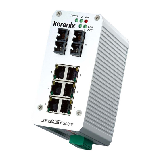
Page 7: Front Panel
2-2 Front Panel The Front Panel of the JetNet 3008/JetNet 3008f Industrial 8-port Fast Ethernet Switch is shown in Figure A. Figure A. Front Panel of the JetNet 3008 / JetNet 3008f. 2-3. Bottom View The bottom view of the JetNet 3008/JetNet 3008f Industrial 8-port Ethernet Switch consists of one 6-pin removable terminal block connector for two DC power inputs and event alarm output. -
Page 8: Led Indicators
Figure B. Bottom view of the JetNet 3008/ JetNet 3008f 2-4. LED Indicators There are some system diagnostic LEDs and Ethernet Port LEDs located on the front panel of JetNet3008 / JetNet 3008f Industrial 8-port Ethernet Switch. These LED indicators provide administrators with real-time system status. -
Page 9: Ports
100Mbps Link (Green The port is operating in full-duplex mode. Fiber port #7, #8 (JetNet 3008f) 100Mbps Activity The port is transmitting or receiving (Green Blinks) packets from the TX device. Table 1 2-5. Ports RJ-45 ports (Auto MDI/MDIX): JetNet 3008 has eight 10/100 Mbps auto-sensing RJ-45 ports for 10Base-T or 100Base-TX device connection and JetNet 3008f has six 10/100Mbps RJ-45 ports and two 100Mbps fiber ports for multi-mode or single-mode fiber cable in SC type connector. -
Page 10: Mounting Installation
Table-2 3. Mounting Installation DIN-Rail Mounting The DIN-Rail clip is already attached on the rear side of JetNet 3008/ JetNet 3008f. JetNet 3008 series supports EN 50022 standard DIN Rail, in the following diagram includes the dimension of EN 55022 DIN Rail for your reference. - Page 11 tightly attached to the track. 4. To remove the JetNet 3008/ JetNet 3008f-m from the track, reverse the steps above.
-
Page 12: Hardware Installation
4. Hardware Installation The following figure illustrates a typical application of JetNet 3008 / JetNet 3008f in field site. It includes Enterprise communication backbone network, Factory communication, field site communication and field site control layers. The control equipments access and report production information through the JetNet 3008 or JetNet 3008f and uplink to factory communication level by fiber or copper which with network redundancy. -
Page 13: Wiring The Dc Power Inputs
4-1. Wiring the DC Power Inputs Follow the steps below to wire JetNet 3008’s / JetNet 3008f’s dual DC power inputs. [Note] The suitable electric wire ranges is from 12 to 24 AWG. V- V+ V- V+ 1. Insert the positive and negative wires into the V+ and V- contacts respectively of the terminal block connector 2. -
Page 14: Wiring The Alarm Relay
4-2. Wiring the Alarm Relay JetNet 3008 /JetNet 3008f provides one dry relay output for power or port link event; the alarm relay is “Normal open” and form a close circuit when The relay conductor ability is 12W when it connects with a DC 24V power source and maximum current is 0.5A. -
Page 15: Wiring Earth Grounding
4-3. Wiring Earth Grounding In the real fields, there might have a lot of automatic device, such as AC motors, electric welding machine, power generator; those devices will generate electromagnetic and disturb communications. To prevent those noises, the switch should be well earthed. In the figure-shows how to make connection. - Page 16 The DIP SWITCH Setting for the Alarm Relay Output is show as following table. Pin No. # Status Description To enable port link down alarm at this port. P1 to P8 (Pin1 ~8) To disable port link down alarm at this port. To enable power failure alarm.
-
Page 17: Cabling
4-5. Cabling The UTP cable connection between the JetNet 3008 and the attached devices (switches, hubs, workstations, etc.) must be less than 100 meters (328 ft.) long. The transmission distance of JetNet 3008f is depends on the type of fiber transceiver model and the attenuation of optical fiber cable. -
Page 18: System Power-On And Testing
1000Base-LH 1000 1550nm,9/125um Single-mode optical fiber cable 70km Optical Fiber cable attenuation Fiber Type Wave length Attenuation /km *1 Attenuation /km *2 Connector loss Splice loss Multi mode 850nm 3.5dBm 2.5dBm 0.75dBm 0.1dBm 50/125um 1310mm 1.5dBm 0.8dBm Multi mode 850nm 3.5dBm 3.0dBm 0.75dBm... - Page 19 7. Connect one side of an Ethernet cable with a RJ-45 connector to the JetNet 3008’s Ethernet port (RJ-45 port), and the other side of the Ethernet cable to target device that equipped IP address and can handle ICMP protocol, like as ping packet. [Note] Make sure that the connected network switches support MDI/MDI-X function.
- Page 20 address 192.168.1.1 as an example. 11. Repeat step 10 to make sure that the connection of each device connected to the JetNet3008 is successfully established. 12. Power on the PC host, activate the Command Line mode, and ping the connected Ethernet device by typing “ping 192.168.1.1 –t” command to see if it will respond.
- Page 21 successfully connected to power sources. When PWR1 fails, the LED for PWR1 will go out. At that moment, if the ping command is still being replied to, then it proves that the redundant power input function works normally.
-
Page 22: Packet Forwarding And Filtering Ability
5. Packet forwarding and filtering ability The JetNet 3008/ JetNet 3008f features packet filtering functions for broadcast packet control protection and QoS. Both of features can provide more graceful performance in a crowded network by traffic filtering and prioritize. This session will introduce the principle of traffic control and forwarding precedence, includes Broadcast control and Quality of Service. - Page 23 IEEE 802.1Q Type of Service for IPv4 /IPv6 packet The JetNet 3008/3008f also provides the IP layer CoS (Class of Service) function by recognizing the priority octet and mapping it to the corresponding priority. For an IPv4 packet, it is embedded in the TOS (type of Service) Octet.
-
Page 25: Trouble Shooting
6. Trouble shooting Make sure you are using the correct DC power suppliers (DC12 to 48 V). Do not use power suppliers with DC output over 48V. It may damage devices. Select Ethernet cables with specifications suitable for your applications to set up your systems. -
Page 26: Technical Specifications
7. Technical Specifications Technology Standard IEEE 802.3 10Base-T Ethernet IEEE 802.3u 100Base-TX /100Base-FX Fast Ethernet IEEE 802.3x Flow Control and Back-pressure IEEE 802.1p Class of Service (CoS) System Performance Switch Technology Store and Forward Technology with 2.0Gbps Switch Fabric System Throughput Mega packets per second, 64 bytes packet size 14,880pps for 10Base-T 148,800pps for 100Base-TX... -
Page 27: Regulatory Approvals
DIN Rail Mounting Case Aluminum metal case with grade 31 protection Dimension (mm) 55(W) x 120(H) x 108 (D) / with DIN Rail Clip JetNet 3008 V3: 0.555Kg Weight JetNet 3008f V3:0.575kg Environmental Operating Temperature -25~70℃ ( JetNet 3008); -40~75 ℃ (JetNet 3008-w) -10~70℃... -
Page 28: Revision History
Revision History Edition Date Modifications V1.0 Nov-2011 Modify from 3008 V2 user manual. Relay 1A, 24V -> 0.5A, 24V ( Drawing) V1.1 26-Jun-2013 Remove – CD User Manual... -
Page 29: About Korenix
Less Time At Work! Fewer Budget on applications! The Korenix business idea is to let you spend less time at work and fewer budget on your applications. Do you really want to go through all the troubles but still end up with low quality products and lousy services? Definitely not! This is why you need Korenix.
Need help?
Do you have a question about the JetNet 3008 v3 and is the answer not in the manual?
Questions and answers