Table of Contents
Advertisement
Quick Links
Advertisement
Table of Contents

Related Manuals for Henny Penny COMPUTRON 7000 500


Summary of Contents for Henny Penny COMPUTRON 7000 500
- Page 3 02213, 01208, and 02502 Computron 7000. This excerpt covers the programming, operation, and troubleshooting information not related to the computer control is contained in the pressure fryer service manual. for the computer control. All other FM01-287...
- Page 4 Henny Penny LIMITED WARRANTY FOR HENNY PENNY APPLIANCES...
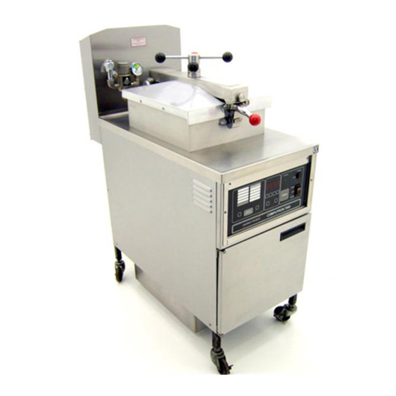
- Page 5 This section describes the functions of all operating controls and their components. escri Decal Switch Menu Board Menu Indicator Done Indicator Digital Display Ready Light High Limit Light i’-- Change Switch Indicators Pressure Light Key Switch Power Switch Timer Switch Reset Usage Switch (Program Mode Only)
- Page 6 Select Function Switch (Program Mode Only) Select Product Switch Select Time Switch Function Display (Program Mode Only) 20127 Primary and Secondary Contactor Thermal Sensor High Limit Thermostat Transformer 24125 Fuses Back-Up High Limit Thermostat (Not Shown) of cook cycles that have been cooked for a particular product. This switch will change the function that is being programmed such as time, temperature, alarm, etc.
- Page 7 ..SF--.‘...
- Page 9 This section provides programming Computron 7000. The operational controls should be read and understood to become familiar functions. If technical assistance is needed, refer to the toll free number printed in this manual. It is recommended to fill out the program worksheet that was shipped with the unit before programming.
- Page 10 Example 1 Time: 12 Minutes Single Stage Chicken Temperature: 325’F Alarm: None Pressure: FUNCTION FUNCTION TIME TIME 12 Min. 12 Min. TEMPERATURE TEMPERATURE 325OF 325OF ALARM ALARM Cannot be Cannot be programmed programmed ;)iYterval 1 1 ;)iYterval PRESSURE PRESSURE Example 2 Time: 13 Minutes Temperature:...
- Page 11 0 to lO..qero meaning no load compen- sation, while ten means the highest load compensation. When dropping a large load of product into the fryer, there is a large temperature drop. On normal controls there is a time period before the thermostat senses this drop.
- Page 12 The filter cycle count is a method of keeping track of when it is time to filter the shortening. To determine when it is time to filter, the control adds the (fractional) number of the cycle count to a running total at the end of each cook cycle. When this total exceeds one, then the “FIL”...
- Page 13 The following are four examples of the idle mode. Example 1: AUTOMATIC IDLE - idle temperature is 250’JF and the idle time is 30 minutes. Control is programmed in eye idle. If no product is cooked within 30 minutes, control will automatically select IDLE and regulate at 250OF.
- Page 14 The one button programming feature is a simple way for the operator to place Henny Penny’s cooking parameters into the control’s memory. These programmed cooking cycles are matched with the menu item cards sent with each unit. To achieve this one button programming, follow these steps: 1.
- Page 15 This feature will aid the operator in the event there is a power outage. If the control is timing down and the power supply is interrupted for any reason, the control will not reset to the original cook cycle time, When power is restored, the control will resume timing at the point the power was interrupted, allowing the operator to know what time is needed to finish cooking that particular’...
- Page 16 1 1. Be sure keyswitch is in the CO ~ 2. Turn the power switch to the cook position. 3. Select desired product using the SELECT P switch. The red indicator will be illuminated beside product. 4. Be sure ready light is illuminated temperature is up to setpoint temperature.
- Page 17 he food preparation procedures, cooking times, temperatures and other parameter settings provided are suggestions to be used as starting points when establishing your specific cooking procedures. Parameter settings for time, temperature, alarm, pressure, load compensation, load anticipation, PC factor and filter cycle may need to be adjusted to produce food products more suitable for your application. : Chicken, 8 or 9 piece cut.
- Page 18 : Chicken breast fillets. - 4 ounces each. - 22 fillets. : 1.’ Wash and drain. 2. Bread with Henny Penny Fryer Mix or marinate and bread. : Chicken gizzards. - 3 pounds. FUNCTION TIME 12:oo 11:oo ‘255 TEMP. ALARM PRESSURE LOAD COMP.
- Page 19 : 5 - 10 pounds. 2. Bread with Henny Penny Fryer Mix or marinate and bread. PRESSURE LOAD COMP. 1 LOAD ANT. 1 PC FACTOR 1 15 1 FIL CYCLE ken livers. : 2 - 6 pounds. 1. Wash and drain.
- Page 20 : 10 pounds. : Potatoes - U.S. No. 1 Grade Idaho 1 - 10 pounds. : 1. Wash, and remove any sprouts. Do not peel. 2. Cut into 8 wedges. 3. Bread with Henny Penny fryer mix. FUNCTION TIME 7:oo TEMP.
- Page 21 1. Clean, wash and drain. 2. Bread with Henny Penny fryer mix or marinate and bread. : Cauliflower. : 1 - 5 large heads. : 1. Clean, rinse and drain. 2. Slice into 1 inch pieces. 3. Bread. LOAD ANT.
- Page 22 Wash and drain. Slice large mushrooms in half. Leave medium and small mushrooms whole. Bread. : Polish sausage or kielbasa. : 1 - 5 pounds. Slice into 2 inch chunks. FUNCTION TIME 2:oo TEMP. ALARM PRESSURE LOAD COMP. INTERVALS INTERVALS...
- Page 23 RQDUCT: Corn dogs (frozen). TOTAL WEIG 5 pounds or approximately 27 corn dogs. “?“- PRESSURE LOAD; COMP. LOAD ANT. PC FACTOk FIL CYCLE Egg rolls (fully cooked, frozen). : 1.5 ounces each. c^” : 1. Thaw if frozen. 2. Fry at 315 or 320OF. FUNCTION TIME 3:oo...
- Page 25 Extreme caution must be taken when connecting these pins to avoid control board damage or electrical shock. With switch in COOK position, the fryer is completely inoperative (no power switch light).
- Page 26 shortening down rror message E-5 display reads HI d display temperature - if display temperature reads HI, unplug power connector from control board. If secondary contactor stays engaged, change contactor - if secondary contactor disengages, change control board If shortening temperature reads normal - defective thermal sensor - replace...
- Page 27 FUSES 15 AMP C363’ C 16 MODEL 500 PRESSURE FRY COMPUTRON 7000 240 VOLT, 3 PHASE...
- Page 28 :46) FIELD JUNCTION BOX (46) WIRING I I I - MODEL 500 PRESSURE FRYEd COMPUTRON 7000 240 VOLT, c9OJ -I 1 PHASE 29616...
- Page 29 1lOJ 36 1. ODEL 500 PRESSURE FRYER COMPUTRON 7000 208 VOLT. 3 PHASE...
- Page 30 (46) c901 (90) (50) C36ft- 1’ (37) MODEL 500 PRESSURE FRYER COMPUTRON 7000 208 VOLT. 1 PHASE 29617...
- Page 31 !I L...
- Page 32 L3 - L2 - Ll - MODEL 500 COMPUTRON 7000 220/380 OR 240/415 VAC 3PH SO/60 HZ 4 POLE, 5 WIRE...
- Page 33 I I I I I I...
- Page 34 :46) FIELD WIRING JUNCTION BOX L‘tYJ (53) c35y (52) ECOl-015 PLUG , -%G- [341 PRESSURE FRYER 7000 1 PHASE VOLT. 29658...
- Page 35 HI-LIMIT THERMOSTAT GAS VALVE TEMP. PROBE MOTOR CONTROL BOARD MODEL 600 PRESSURE FRYER COMPUTRON 7000 120 VOLT 50160 CONNECTOR...
- Page 36 GAS VALVE temp. MOTOR MODEL 600 PRESSURE FRYER ,COMPUTRON 7000 VOLT SO-60 CONNECTOR 29701...
- Page 37 VALVE SAFETY VALVE GA5 VALVE temp. probe MODEL 600 PRESSURE FRYER COMPUTRON 7000 2201240 VOLT 50160 CONNECTOR...
- Page 38 = FIELD CONNECTION SO/60 FILTER unTnn SAFETY VALVE VI” I “l-l PUMP t mV14A 25A' hl5* NOTE: THIS WIRING DIAGRAM MUST BE USED IN CONJUNCTION WITH THE WIRING DIAGRAM ORIGINALLY SUPPLIED WITH THE FRYER. GAS FRYER HZ WITH GAS SAFETY VALVE 34436...
- Page 39 --i-=-Y FUSE 15 oap 3I 4, MODEL 561 13.5KW FILTER MOTOR PUMP ELECTRIC FRYER 3PH 208/240VAC 48123...
- Page 40 MODEL 561 13.5KW 3PH AT 220/380VAC OR 240/415VAC ELECTRIC FRYER PO\JER TRT;;;;;ER 380VAC 4 1 SVAC 240VAC 8153...
- Page 41 > FUSE 15 OmP 24 l--- --- ’ ‘I MODEL 561 ELECTRIC FRYER 13.5KW 3PH 480VAC...
- Page 42 MODEL 561 ELECTRIC FRYER 13.5KW RELAY 240VAC 3PH 220VAC CONTROL BOARD 48167...
-
Page 44: Parts List
RECOMMENDED SPARE PARTS FOR are indicated with √ in the parts lists. Please use care when DISTRIBUTORS The following are replaceable parts for the gas and electric Computron. (Refer to drawing in operation section) Item Part Number Number √ 26 16684 √... - Page 45 BLE CORE DISC ASSEhABLY ROUNDED EDGE OF TOWARD DISC SPRING GUIDE (ITE SEAT IN ANY WAY as a ectric...
- Page 46 FIGURE & ITEM PART NUMBER √ 2* 17120 17101 17109 17110 17111 17112 17114 17115 17116 17117 17122 √ 13 17102 √ 14 17103 √ 15 17104 √ 16 17105 √ 17 29547 √ 17 18706 √ 17 18726 √ 18 17123 √...
- Page 48 FIGURE & ITEM PART NUMBER √ 1a 29614 √ 1b 29728 √ 2 29688 √ 2 29729 √ 3 16253 √ 4 16352 √ 5 16267 √ 6* 38468 √ 6* 38467 √ recommended parts *not shown DESCRIPTION GAS CONTROL VALVE (Gas Model) VALVE, Control, Natural Gas, 24 Volt VALVE, Control, Propane Gas, 24 Volt...
- Page 49 f‘...
- Page 50 The green PRESSURE light will turn on during the cook cycle if the control calls for pressure. Pressure gauge shows the actual pot pressure. Use idle mode to conserve energy and shortening life. It can be entered manually or automatically. Put the fryer into Idle mode by pushing SELECT PRODUCT until the red IDLE light (in the menu area) turns on.
- Page 51 Temperatures can be programmed from 1’70 to 390 degrees F. If you try to go beyond these limits, the buzzer will sound and the display will blank, then go to 170 or 390. 0 Alarms and pressures can be turned on or off using any change switch. The display will show “on” or “off”. Four times affect the whole cook cycle.
Need help?
Do you have a question about the COMPUTRON 7000 500 and is the answer not in the manual?
Questions and answers