Table of Contents
Advertisement
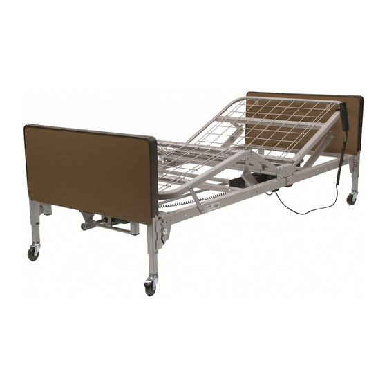
MODEL US0208 / US0208PL SEMI-ELECTRIC BED
MODEL US0458 / US0458PL FULL-ELECTRIC / LOW BED
USER MANUAL
READ THIS MANUAL BEFORE OPERATING THE PATRIOT
HOMECARE BED.
™
SAVE THIS MANUAL FOR FUTURE USE.
INFO: THE MOST CURRENT VERSION OF THIS MANUAL
CAN BE FOUND ONLINE AT www.grahamfield.com
US0208-INS-LAB-RevD11
Advertisement
Table of Contents

Related Manuals for Lumex PATRIOT US0458


Summary of Contents for Lumex PATRIOT US0458
-
Page 1: User Manual
MODEL US0208 / US0208PL SEMI-ELECTRIC BED MODEL US0458 / US0458PL FULL-ELECTRIC / LOW BED USER MANUAL READ THIS MANUAL BEFORE OPERATING THE PATRIOT HOMECARE BED. ™ SAVE THIS MANUAL FOR FUTURE USE. INFO: THE MOST CURRENT VERSION OF THIS MANUAL CAN BE FOUND ONLINE AT www.grahamfield.com US0208-INS-LAB-RevD11... -
Page 2: Table Of Contents
GF Health Products, Inc. is not responsible for typographical errors. Packaging, warranties, products and specifications are subject to change without notice. Graham-Field and Lumex are registered trademarks, and Patriot is a trademark, of GF Health Products, Inc. © 2011, GF Health Products, Inc. -
Page 3: Safety
This includes when assisting the user in repositioning or transferring in or out of bed. WARNING: In order not to invalidate the warranty or create a hazardous condition resulting in serious personal injury, GF Health Products, Inc. recommends the use of only Lumex replacement parts. -
Page 4: Introduction, Patriot Homecare Bed User Manual
2 INTRODUCTION, PATRIOT HOMECARE BED USER MANUAL This manual contains assembly and maintenance instructions for your Model US0208 / US0208PL Semi-Electric and US0458 / US0458PL Full-Electric / Low Patriot bed. Read the entire manual care- fully before using your bed, and refer to it during use if you have questions. THERMAL MOTOR PROTECTION This product is powered by a quiet, efficient DC motor system. -
Page 5: Assembly Instructions
3 ASSEMBLY INSTRUCTIONS HEAD AND FOOT ASSEMBLY hook rivet motor cam foot head section section hook rivet Assembly, head and foot sections Note: Grid deck not shown for clarity 1. Place the head and foot sections on their sides at approximately right angles to each other with motor cams up, as shown above. -
Page 6: Motor Assembly
MOTOR ASSEMBLY WARNING: Assemble motor on bed as follows. While it is possible to install the motor backwards, avoid it! Incorrect installation could cause Head the bed to move in unexpected ways. Note that the motor ends are labeled and embossed with head and foot symbols (shown at right). Ensure that bed head and motor head, and bed foot and motor foot, are matched. -
Page 7: Install Motor Slide Caps
pressure Install motor slide caps 7. Position the caps as shown at right so that the grooves in the slide cap are aligned with slide cap the grooves in the motor. 8. Apply straight downward pressure to each end of the cap while sliding into the closed position. -
Page 8: Full-Electric Bed Only (Us0458 / Us0458Pl): Caster Position
FULL-ELECTRIC BED ONLY (US0458 / US0458PL): CASTER POSITION Any full-electric Patriot bed can be used as either a standard-height or low-height bed by moving the casters. fig 1: casters mounted at fig 2: casters mounted at low fig 3: casters mounted at low standard height height, bed in lowest position height, bed in elevated position... -
Page 9: Bed End Assembly
BED END ASSEMBLY All bed models: Assemble bed head end 1. Insert one locking and one non-locking caster into bed end. Locking casters must be installed diagonally from each other. See previous page for full-electric caster position options. 2. Standing directly in front of the bed end, position it as close to the bed as possible. 3. -
Page 10: All Models: Install Bed End Locking Hardware
All models: Install bed end locking hardware 1. After bed head end has been attached, install nylon cord Bed End Locking Hardware to act as a latch fender for each corner. washer Bed End Locking Hardware, part number hairpin clevis pin 690-1000-100, includes four lanyards, each as- clip with hole... - Page 11 5. From the inside, reattach the hairpin clip to the cord’s looped end as shown in d. This prevents the cord from slipping back through the frame bracket hole. 6. From the outside, insert lanyard clevis pin with washer into the small hole directly below the bed end bracket top hook so that the washer rests against the bracket, as shown in e.
-
Page 12: Full-Electric Bed Only (Us0458 / Us0458Pl): Assemble Hi/Lo Motor Shaft To Foot End Gear Box
Full-electric bed only (US0458 / US0458PL): Assemble hi/lo motor shaft to foot end gear box hi/lo motor FOOT notches in hi/lo motor shaft coupler slide over gear box shaft pin gear box hi/lo motor shaft Attach hi/lo motor shaft to foot end gear box You must first attach the coupler end of the motor shaft to the foot-end gear box (see above). -
Page 13: Hi/Lo Rod Assembly / Bed Length
HI/LO ROD ASSEMBLY / BED LENGTH The hi/lo rod assembly consists of an inner and outer tube with a spring button lock to keep them together. 1. Assemble outer and inner tubes: Semi-electric bed only (US0208 / US0208PL): Assemble hi/lo rod Hi/lo rod assembly semi-electric bed US0208 / US0208PL... -
Page 14: All Models: Attach Hi/Lo Rod To Gearbox Or Motor Shaft Pins
All models: Attach hi/lo rod to gearbox or motor shaft pins Both ends of the hi/lo rod assembly have a slot to mount on the foot end motor shaft pins and bed end gearbox shaft pins. Follow steps 2-3 to mount the hi/lo rod assembly on the gearboxes. notch at end of hi/lo rod rests over pin at end of m otor shaft FOOT END... -
Page 15: Bed Operation
4 BED OPERATION WARNING: Ensure that bed is secure and assembled as instructed on previous pages before operating. Plug the power cord into any grounded outlet. WARNING: Do not leave the bed unattended when plugged in. Info: In the event of a power failure, use a standard 9V battery to lower the bed’s head and foot sections (the 9V battery connection is attached to the motor). -
Page 16: Crank Operation: Semi-Electric Bed Only (Us0208 / Us0208Pl)
CRANK OPERATION: SEMI-ELECTRIC BED ONLY (US0208 / US0208PL) Use the crank at the center foot of the semi- foot electric bed (shown at right) to change bed height (raise or lower entire deck). crank Crank operation TRENDELENBURG POSITION, ALL MODELS (HEAD END AT LOWER ELEVATION THAN FOOT END) 1. -
Page 17: Specifications, All Models
5 SPECIFICATIONS, ALL MODELS * * Specifications are subject to change without notice. Deck High position height Deck height: High Position US0208 / US0208PL: US0458 / US0458PL with cast- US0458 / US0458PL with 24.0 inches ers in low position: 20.0 inches casters in standard position: 23.5 inches Low position... -
Page 18: Accessories: Bed Rails
6 ACCESSORIES: BED RAILS Patriot Homecare Bed decks are equipped with patent-pending slots specifically for bed rail instal- lation, providing a fixed place to mount GF bed rails. Two styles of Lumex bed rails are described in Section 6: 1) The Lumex Patriot Liberty bed rail system, designed specifically for Patriot Beds, and 2) Lumex Universal bed rails Please read the following bed rail safety information. -
Page 19: Gf6580B-1: Quarter Rail
GF6580B-1: Quarter Rail head end slot foot end pivot point pivot point foot end pivot point slot slot head end pivot head end foot end slot point slotted foot deck angle head deck foot end foot end angle GF6580B-1 foot end slots Quarter Rail head end slots The Quarter Rail, shown above, is approximately 18 inches in length when mounted on the Patriot... -
Page 20: Lumex Universal Bed Rails
LUMEX UNIVERSAL BED RAILS If you install Lumex universal bed rails, follow the installation instructions that accompany them; the following instructions are provided to describe the differences between the installation of bed rail crossbraces on Patriot grid beds and spring beds. -
Page 21: Gf6580A-1: Low Universal Half Rail
GF6580A-1: Low Universal Half Rail Cable tie GF6580A-1 Low Universal Half Rail Follow same procedure for mounting half rails on foot-end using G3 slots. Secure crossbrace to head deck angle with cable tie SUGGESTED Spring Buttons Spring Buttons RAIL TO HEADBOARD MINIMUM OF 9.25"... -
Page 22: Service Parts, All Models
7 SERVICE PARTS, ALL MODELS Service parts for all bed models are shown below and on the following two pages. See pictures and tables for appropriate service parts. Info: To order service parts, contact our Customer Service department at 800-365-2338 (fax 920-929-8213). -
Page 23: Bed End Components
BED END COMPONENTS HEAD FOOT Item Part number Description Semi-electric Full-electric US0208 US0208PL US0458 US0458PL 690-7001-901 Head bed end, semi-electric, walnut panels 690-7601-901 Head bed end, semi-electric, plastic panels 690-7004-901 Head bed end, full-electric, walnut panels 690-7604-901 Head bed end, full-electric, plastic panels 690-7001-902 Foot bed end, semi-electric, walnut panels 690-7601-902... -
Page 24: Bed Service Parts
BED SERVICE PARTS HEAD FOOT Item Part number Description Semi-electric, H7920SE Full-electric, H7920FE US0208 / US0208PL US0458 / US0458PL 690-2001-913 Motor and pendant hand control, semi-electric 690-2001-411 Pendant hand control, semi-electric 690-3001-943 Motor and pendant hand control, full-electric 690-2001-414 Pendant hand control, full-electric 690-7001-944 Motor and bracket, hi/lo 690-3001-945... -
Page 25: Maintenance And Safety Checks
8 MAINTENANCE AND SAFETY CHECKS Perform the following as needed or between patient placements, whichever happens sooner: Electronics and Check all controls to ensure that all functions work Foot control properly. Motors Head control Hi/Lo (if applicable) Check all cables for damaged or frayed wires. Power cord Pendant hand control cord Check to ensure that all plugs are fully inserted or attached. -
Page 26: Warranty
9 WARRANTY GF Health Products, Inc. warrants the Patriot US0208 / US0208PL Semi-Electric Homecare Bed Patriot US0458 / US0458PL Full-Electric / Low Bed as follows: Two-year limited warranty for defects in workmanship and materials of mechanical components, frame, and electronics. -
Page 27: Index
Head and foot assembly instructions 5 Hi/lo rod assembly 13 Info statement, significance 3 Introduction 3 Lumex Patriot Liberty bed rails 18 Lumex universal bed rails 20 Maintenance, bed frame and sleeping surface 25 Maintenance, cleaning 25 Maintenance, electronics 25... - Page 28 U.S.A. Corporate Headquarters: GF Health Products, Inc. (“Graham-Field”) 2935 Northeast Parkway Atlanta, Georgia 30360 telephone: 770-368-4700 www.grahamfield.com...
Need help?
Do you have a question about the PATRIOT US0458 and is the answer not in the manual?
Questions and answers