Table of Contents
Advertisement
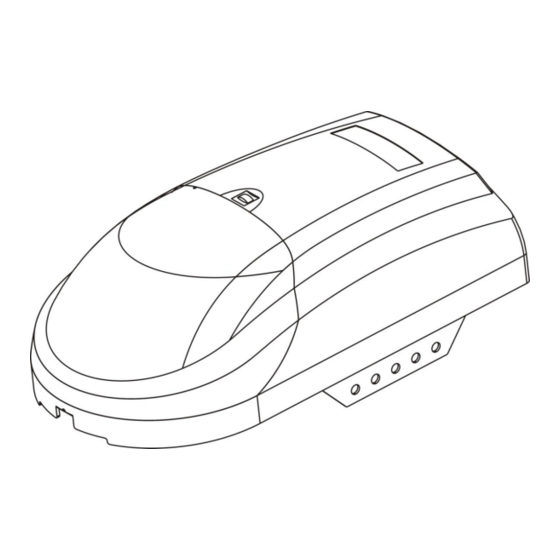
Sectional and Tilting Door Opener
Installation Instructions and User Guide
ET-600E
ET-800E
ET-1000E
S/N
WARNING
Please read the manual carefully before installation and use. The installation of your
new door opener must be carried out by a technically qualified or licensed person.
Attempting to install or repair the door opener without suitable technical qualification
may result in severe personal injury, death and / or property damage.
Advertisement
Table of Contents

Related Manuals for Etdoor ET-600E


Summary of Contents for Etdoor ET-600E
- Page 1 Sectional and Tilting Door Opener Installation Instructions and User Guide ET-600E ET-800E ET-1000E WARNING Please read the manual carefully before installation and use. The installation of your new door opener must be carried out by a technically qualified or licensed person.
-
Page 2: Table Of Contents
CONTENTS Important Safety Recommendations...…………………………….……………………………..1-2 Basic function introduction………………………………………………………………………..2 Special function introduction………….……………………..……………………………………..2 Installation (aluminum track)………………………………………….…………………………..3-4 Installation (steel track)………………………………………….…………………………….…….5 Installation (sectional steel track)………………………………………………………………..6-9 Installation recommendations……………………………………………………………………..10 Basic function setting and applying……………………………………………………………..11-12 Special function introduction and application………………………………………….……….13-14 PCB structure………………..…………………………………………………………..……….. 14 Aluminum, steel & sectional steel accessory list…………………..…………………….……...15 Manual disengagement…………………………………………………………………………….16 Maintenance………………………………………………………………………………………...16 Technical specifications…………………………………………………………………………….17... -
Page 3: Important Safety Recommendations
Important safety recommendations FAILURE TO COMPLY WITH THE FOLLOWING SAFETY RECOMMENDATIONS MAY RESULT IN SERIOUS PERSONAL INJURY, DEATH AND / OR PROPERTY DAMAGE. 1. PLEASE READ CAREFULLY AND ADHERE TO ALL SAFETY AND INSTALLATION RECOMMENDATIONS. 2. The opener is designed and manufactured to meet local regulations. The installer must be familiar with local regulations required in respect of the installation of the opener. -
Page 4: Basic Function Introduction
may cause injury. Each month check that the drive reverses when the door contacts a 50 mm high object placed on the floor. Adjust if necessary and recheck since an incorrect adjustment may present a hazard, for drives incorporating an entrapment protection system depending on contact with the bottom edge of the door. -
Page 5: Installation (Aluminum Track)
Referring to Fig. 2 for recommended installation 1) Sectional door rail 5) O/S/C button 2) 24V DC flash light (optional extra) 6) Power socket 3) Wall switch 7) Door opener 4) Photo beam (RX/TX Type) CHAIN SHUTTLE ASSEMBLY As for the ease of the chain, it is delivered with the chain and chain shuttle already assembled in the track. - Page 6 Before attaching the motor brackets (E) (FIG 4) screw an inverted nut (6mm) (D) on each stud then position the brackets (E) on the studs and secure them in-place using a second 6mm-nut and then lock the brackets to the rail by tightening the inverted lock nuts (D).
-
Page 7: Installation (Steel Track)
Installation (steel track) Fig. 1 1. Fixing the track bracket. Fixing the track bracket to the wall 2cm-15cm over the shaft or intermediate bracket (depend on the actual installation space). 2. Fixing the steel track to the bracket with copper pin. (Fig. 1) 3. -
Page 8: Installation (Sectional Steel Track)
Installation (sectional steel track) - Page 11 1. Assembly section (Fig. 1) Grease inside edges of rail sections using grease. Place rail pieces (1.1) on flat surface for assembly. All four rail sections are interchangeable. Slide rail brace (1.2) onto rail section. Connect rail by sliding rail brace onto next rail section. Tap rail assembly on piece of wood until the rail sections are flush.
-
Page 12: Installation Recommendations
Installation recommendations there are specific standards that have to be strictly followed regarding the safety Remember rules of electrical installations and automatic gates and doors. As for the legal requirements and standards that must be adhered to, please take notice of the following points to ensure maximum safety and reliability of your installation. -
Page 13: Travel Limit Setting
Basic function setting and applying 1. Travel limit setting Opening & closing force self-learning Press ‘SET’ button and hold on until the LED displays figure ‘1’, then adjust the up limit by pressing ‘up’ button. Fine-tuning ‘up’ or ‘down’ button to determine the final up limit position then press ‘set’... - Page 14 4. Transmitter lock Press ‘SET’ button and hold on until the LED displays 4. It’s in lock door programming mode. Then press ‘UP’ button, the LED displays 1, the transmitter lock function is available. Press ‘DOWN’ button the LED displays 0, the lock function has been turned off.
-
Page 15: Special Function Introduction And Application
Special function introduction and application The following functions are made to order in accordance with the special needs of customers: 1.The O/S/C interfaces available Add another O/S/C button to open or close the door. 2.Auto safety reverse function This special function is for safety consideration. Reverse force and time are in accordance with European Union standard. -
Page 16: Pcb Structure
Fig. 3 PCB structure... -
Page 17: Aluminum, Steel & Sectional Steel Accessory List
Aluminum track accessory list Item Quantity Clutch Components Bracket for door panel Bracket for track Clutch cord Cord pendant ø 1.8×38 Cotter pin M6X14 hexagon head bolt M6 flange ø 8×25 axis pin M8X16 hexagon head bolt M8 flange Motor bracket ø8*90 axis pin 28×18 fixing kit 10×15 fixing kit... -
Page 18: Manual Disengagement
Manual disengagement The opener is equipped with a manual release cord to disengage shuttle and move door by hand while holding the handle down (Fig 8). Pull on the handle to disengage the shuttle. To re-engage the door simply run opener in automatic mode or move door by hand until the trolley engages in the chain shuttle. -
Page 19: Technical Specifications
Technical specifications 150W; 220 – 240 V AC, 50Hz or 110 - 120V AC, 60Hz Power Input: (subject to customer’s area) Motor: Light time: 3 minutes Working temperature: -20° ~ 40° C Relative Humidity: <90% Max force: 600N Rated load: 300N Reception frequency: 433.92 MHz or according to customer’s requirement...
Need help?
Do you have a question about the ET-600E and is the answer not in the manual?
Questions and answers