Table of Contents
Advertisement
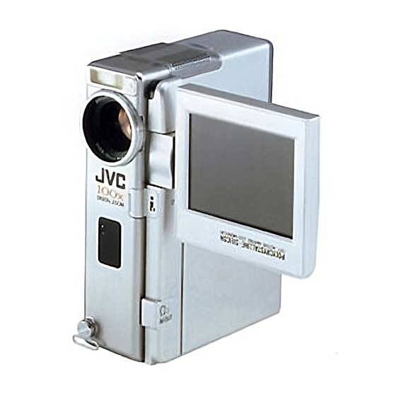
DIGITAL VIDEO CAMERA
GR-DVX7
Please visit our CyberCam Homepage on the
World Wide Web and answer our Consumer
Survey (in English only):
http://www.jvc-victor.co.jp/english/index-e.html
INSTRUCTIONS
CONTENTS
Basic Recording For Video ............................ 18
Basic Recording For Video And D.S.C. .............. 24
Advanced Features For Video And D.S.C. .......... 26
Basic Playback For Video ............................. 52
Advanced Features For Video ........................ 54
Basic Playback For D.S.C. ............................ 56
Advanced Features For D.S.C. ....................... 57
Advanced Features For Video And D.S.C. .......... 68
Basic Connections ...................................... 70
Advanced Connections ................................ 72
Images/Sounds Between Tapes .................. 75
In A MultiMediaCard To A Tape .................. 76
On A Tape To A MultiMediaCard ................. 77
Communication [IrTran-P] ......................... 78
Random Assemble Editing ............................ 84
For More Accurate Editing ............................ 88
Audio Dubbing ......................................... 90
Initializing A MultiMediaCard ........................ 91
Docking Station ........................................ 99
Controls, Connectors And Indicators .............. 100
Indications ............................................ 102
Terms .................................................. 106
LYT0400-001A
5
6 - 7
8 - 17
18 - 51
52 - 73
74 - 79
80 - 90
91
92 - 97
98
99 - 106
107 - 108
109 - 110
EN
Advertisement
Table of Contents

Related Manuals for JVC GR-DVX7


Summary of Contents for JVC GR-DVX7
-
Page 1: Table Of Contents
DIGITAL VIDEO CAMERA Basic Recording For Video ......18 Basic Recording For Digital Still Camera (D.S.C.) ... 22 Basic Recording For Video And D.S.C....24 GR-DVX7 Advanced Features For Video And D.S.C... 26 PLAYBACK 52 – 73 Basic Playback For Video ......52 Advanced Features For Video ...... -
Page 2: Safety Precautions
Dear Customer, Thank you for purchasing this digital video camera. Before use, please read the safety information and precautions contained in the following pages to ensure safe use of this product. Using This Instruction Manual •All major sections and subsections are listed in the Table Of Contents ( cover page). - Page 3 NOTES: This camcorder is designed to be used with PAL- type colour television signals. It cannot be used The rating plate (serial number plate) and safety for playback with a television of a different caution are on the bottom and/or the back of standard.
- Page 4 SAFETY PRECAUTIONS Do not point the lens or the viewfinder directly into the sun. This can cause eye injuries, as well as lead to the malfunctioning of internal circuitry. There is also a risk of fire or electric shock. CAUTION! The following notes concern possible physical damage to the camcorder and to the user.
-
Page 5: About Dv
ABOUT DV ABOUT DV The digital camcorder converts incoming audio and video signals into digital form for recording. A video signal is composed of a luminance signal (Y) and colour signals (R-Y and B-Y). These signals are identified and recorded digitally (Digital Component Recording). The A/D (Analogue to Digital) converter samples the Y signal at 13.5 MHz, and R-Y and B-Y at 6.75 MHz, and changes them to an 8-bit quantum signal. -
Page 6: Provided Accessories
PROVIDED ACCESSORIES •Docking Station CU-V501E •AC Power Adapter/Charger AA-V50EK •Remote Control Unit RM-V713U •Battery Pack BN-V507U •CD-ROM The CD ROM contains the •DC Cord following 7 software programmes: JLIP Video Capture JLIP Video Producer Picture Navigator (for Windows ® Picture Navigator (for Macintosh ®... - Page 7 •PC Connection Cable •JLIP Cable •Audio/Video (A/V) Cable •Audio/Video (A/V) Cable [mini-plug to RCA plug] [RCA plug to RCA plug] •S-Video Cable •Editing Cable •Cable Adapter •Core Filter x 3 (for optional DV cable, headphones and microphone) •Cleaning Cloth...
-
Page 8: Getting Started
GETTING STARTED Power CHARGING THE BATTERY PACK This camcorder’s 2-way power supply system lets SUPPLY POWER TO CHARGER you choose the most appropriate source of power. Make sure you unplug the camcorder’s DC cord from the NOTES: AC Power Adapter/Charger. Plug the AC Adapter/Charger’s power cord into an AC No function is available without power supply. -
Page 9: Using The Battery Pack
USING THE BATTERY PACK ATTACH BATTERY PACK Insert the terminal end of the battery pack into the battery pack mount, then firmly push the end the battery pack in the direction of the arrow until it locks into place as shown in the illustration. •If the battery pack is attached in the wrong position, a malfunction may occur. -
Page 10: Viewfinder Adjustment
GETTING STARTED (cont.) Grip Adjustment START/STOP Button EXPAND LOOP Power Zoom Lever Separate the Velcro strip. INSERT HAND Pass your right hand through the loop and grasp the grip. ADJUST STRAP LENGTH Adjust so that your thumb and fingers can easily operate START/STOP and Power Zoom Lever. -
Page 11: Date/Time Settings
Date/Time Settings Operation Switch Date and time will automatically be recorded on tape at all times. It is your choice to display it or not during playback ( pg. 55). SELECT OPERATION MODE Set the Operation Switch to “ ”. Then, set the Power Switch to “... - Page 12 GETTING STARTED (cont.) Loading/Unloading A Cassette Cassette holder The camcorder needs to be powered up to load or eject a cassette. OPEN CASSETTE COVER Make sure the Slide OPEN/EJECT in the direction of the arrow then window side is swing the cover open until it locks. The holder opens facing out.
-
Page 13: Recording Mode Setting
Recording Mode Setting Operation Switch Set the tape recording mode according to your preference. SELECT OPERATION MODE Set the Operation Switch to “ ”. Then, set the Power Switch to “ ” or “5S” while pressing down the Lock Button. Open the LCD monitor fully or pull out the viewfinder fully. -
Page 14: Loading A Multimediacard
GETTING STARTED (cont.) Loading A MultiMediaCard CONFIRM POWER-OFF STATUS Make sure the camcorder’s power is off Card Cover OPEN THE CARD COVER INSERT THE MULTIMEDIACARD Insert the MultiMediaCard terminal end first with the label facing up (see the illustration on the left). •Do not touch the terminal. -
Page 15: Picture Quality Mode Setting
Picture Quality Mode Setting Operation Switch The Picture Quality mode can be selected to best match your needs. Three Picture Quality modes are available: FINE, STANDARD and ECONOMY (in order of quality). SELECT OPERATION MODE Set the Operation Switch to “ ”. -
Page 16: Tripod Mounting
GETTING STARTED (cont.) Tripod Mounting ALIGN AND TIGHTEN Align the screw on the tripod with the camera’s mounting socket. Then tighten the screw. CAUTION: When using a tripod, be sure to open and extend its legs fully to stabilise the camcorder. To prevent damage to the unit caused by falling over, do not use a small-sized tripod. -
Page 17: Recording
Operation Mode To turn on the camcorder, first set the Power Switch to any operation mode except “OFF”, Turning the Power Switch and Operation Switch allows then pull out the viewfinder fully or open the you to choose the appropriate operation mode among the LCD monitor. -
Page 18: Basic Recording For Video
RECORDING Basic Recording For Video NOTE: Operation Switch You should already have performed the procedures listed below. If not, do so before continuing. Power ( pg. 8) Grip Adjustment ( pg. 10) Viewfinder Adjustment ( pg. 10) Recording Mode Setting ( pg. -
Page 19: Stop Recording
STOP RECORDING Press START/STOP again to stop recording. •The camcorder re-enters the Record-Standby mode. NOTES: The image will not appear simultaneously in the LCD monitor and the viewfinder. No image appears on the LCD monitor when the viewfinder is pulled out. It is not possible to shoot using both LCD monitor and view- finder. -
Page 20: Shooting While Watching The Lcd Monitor
RECORDING Basic Recording For Video (cont.) Shooting While Watching The LCD Monitor Before the following steps, perform step 1 ( pg. 18). ENTER RECORD–STANDBY MODE Make sure the viewfinder is pushed back in. Set the Operation Switch to “ ” or “ ”. -
Page 21: Journalistic Shooting
Journalistic Shooting In some situations different angles of shooting may be required for more dramatic results. OPEN LCD MONITOR Make sure the LCD monitor is fully open. TILT LCD MONITOR Tilt the LCD monitor in the most convenient direction. •The LCD monitor can rotate almost full circle (270°: 90°... -
Page 22: Basic Recording For Digital Still Camera (D.s.c.)
RECORDING Basic Recording For Digital Still Camera (D.S.C.) Basic Shooting (Snapshot) You can use your camcorder as a Digital Still Camera (D.S.C.) for taking snapshots. Still images shot in the D.S.C. mode (when the Power Switch is set to “ ”) are recorded in the MultiMediaCard. - Page 23 To Record An Image With A Title/Frame . . . PIN-UP ..refer to “Superimposing A Title/Frame” ( pg. 69). Pin-Up mode* To Remove The Shutter Sound ..when you don’t want to hear the shutter sound, set BEEP/TALLY to “OFF”...
-
Page 24: Basic Recording For Video And D.s.c
RECORDING Basic Recording For Video And D.S.C. Zooming Zoom in (T: Telephoto) FEATURE: PURPOSE: To produce the zoom in/out effect, or an instantaneous change in image magnification. OPERATION: Zoom In Slide the Power Zoom Lever towards “T”. Zoom Out Zoom out (W: Wide angle) Slide the Power Zoom Lever towards “W”. - Page 25 NOTE: Recording From The Middle Of A Tape Time Code During recording, a time code is recorded on the tape. This code is to confirm the location of the recorded scene on the tape during playback. If recording starts from a blank portion, the time code begins counting from “00:00:00” (minute:second:frame).
-
Page 26: Advanced Features For Video And D.s.c
RECORDING Advanced Features For Video And D.S.C. Displaying The Date And Time During RECORDING Advanced Features Operation Switch Recording When the Operation Switch is set to “ ”, you can choose whether to display the date and time during recording or not. -
Page 27: Lcd Monitor/Viewfinder Indications
LCD Monitor/Viewfinder Indications Operation Switch You can make the LCD monitor/Viewfinder indications appear/disappear. SELECT OPERATION MODE Set the Operation Switch to “ ”. Then, set the Power Switch to “ ”, “5S” or “ ” while pressing down the Lock Button. ACCESS RECORDING MENU Press MENU/SET. - Page 28 RECORDING Advanced Features For Video And D.S.C. (cont.) Scene (5-second recording) Operation Switch Record a vacation or an important event in 5-second clips to keep the action moving. This function is available only for video recording. SELECT OPERATION MODE Set the Operation Switch to “ ”...
- Page 29 Self-Timer Operation Switch Once the camcorder is set, the camcorder operator can become part of the scene in a more natural way, adding the final touch to a memorable picture. SELECT OPERATION MODE Set the Operation Switch to “ ”. Then, set the START/STOP Power Switch to “...
-
Page 30: Motor Drive Mode
RECORDING Advanced Features For Video And D.S.C. (cont.) Snapshot (For Video Recording) Use your camcorder like a regular camera and take a snapshot, or several of them in succession. This feature lets you record still images that look like photographs onto a tape. SNAPSHOT MODE SELECTION SELECT OPERATION MODE Set the Operation Switch to “... - Page 31 NOTES: PIN-UP Even if “MULTI-4” or “MULTI-9” is engaged, Snapshot Pin-Up mode* recording will be performed in the FULL mode during Digital Zoom. However, the flash will not fire. If Snapshot recording is not possible, “PHOTO” blinks when PHOTO (SNAPSHOT) is pressed. Even if Programme AE with special effects ( pg.
- Page 32 RECORDING Advanced Features For Video And D.S.C. (cont.) Snapshot Flash (Auto Flash) Operation Switch In Full Auto or Manual mode, when “FLASH” is set to “AUTO” or “AUTO ” in the Mode Menu, the flash automatically fires if it’s dark ( appears) when a snapshot is taken in Record-Standby.
-
Page 33: Flash Brightness Adjustment
Flash Brightness Adjustment Operation Switch When a snapshot ( pg. 22, 30) is taken in the dark the camcorder fires the flash ( pg. 32) and adjusts the brightness automatically. You can also adjust the flash brightness manually. When you find that the snapshots you took look too bright or too dark, adjust it manually. -
Page 34: Mode Menu
RECORDING Advanced Features For Video And D.S.C. (cont.) Using Menu For Detailed Adjustment Operation Switch This camcorder is equipped with an easy-to-use, on-screen menu system that simplifies many of the more detailed camcorder settings ( pg. 35 – 39) . SELECT OPERATION MODE Set the Operation Switch to “... -
Page 35: Power Switch
[Power Switch: [Power Switch: or 5S] Power lamp Power lamp Display Display FOCUS MANUAL FOCUS MANUAL EXPOSURE AUTO Recording Menu EXPOSURE AUTO Recording Menu W. BALANCE AUTO W. BALANCE AUTO FADER P. AE / WIPE / EFFECT P. AE FLASH ADJ. / EFFECT TO MODE MENU FLASH ADJ. - Page 36 RECORDING Advanced Features For Video And D.S.C. (cont.) Recording Menu Explanations FOCUS Refer to “Focusing” ( pg. 46, 47). EXPOSURE Refer to “Exposure Control” and “Iris Lock” ( pg. 48, 49). Refer to “White Balance Adjustment” and “Manual White Balance Operation” W.BALANCE pg.
- Page 37 Mode Menu Explanations REC MODE Allows you to set the recording mode (SP or LP) depending on your preference ( pg. 13). Select “OFF” when you want to use neither “SQUEEZE” nor WIDE MODE “CINEMA”. For playback on TVs with an aspect ratio of 16:9. Naturally expands SQUEEZE the image to fit the screen without distortion.
- Page 38 RECORDING Advanced Features For Video And D.S.C. (cont.) Date/Time Menu Explanations Makes all the indications appear in the camcorder ( pg. 27). INDICATION Keeps all the indications (except the tape running indicator, warnings, etc.) from appearing in the camcorder ( pg.
- Page 39 System Menu Explanations Usually the distance to a subject where the lens is in focus depends on the TELE MACRO zoom magnification. Unless there is a distance more than 1m to the subject, the lens is out of focus at the maximum telephoto setting. When set to “ON”, you can shoot a subject as large as possible at a distance of approx.
- Page 40 RECORDING Advanced Features For Video And D.S.C. (cont.) Multi Screen Mode The screen is divided into 9 quadrangles, with the scene you are aiming at appearing in each one. This 9-quadran- gle image can be recorded onto a tape or into a MultiMediaCard.
- Page 41 Fade/Wipe Effects Operation Switch IMPORTANT: If certain modes of Programme AE with special effects pg. 44) are activated, some Fade/Wipe Effects cannot be used. If you select a Fade/Wipe Effect that is unusable in the current situation, the indication blinks. START/STOP These effects let you make pro-style scene transitions.
-
Page 42: Start Recording
RECORDING Advanced Features For Video And D.S.C. (cont.) PICTURE WIPE OR DISSOLVE SELECTION Combine the Picture Wipe and Dissolve functions for a professional transition effect. There are 6 Picture Wipe effects and 1 Dissolve effect. The Picture Wipe or Dissolve START/STOP Button works when recording is started. - Page 43 Fader And Wipe Menu Menu Effect Fade in or out with a white screen. FADER — WHITE Fade in or out with a black screen. FADER — BLACK Fade in or out with a full-screen mosaic effect. FADER — MOSAIC Fade in to a colour screen from a black and white screen, or fade out FADER —...
-
Page 44: Programme Ae With Special Effects
RECORDING Advanced Features For Video And D.S.C. (cont.) Programme AE With Special Effects Operation Switch IMPORTANT: If certain Fades or Wipes ( pg. 43) are activated, some modes of Programme AE with special effects cannot be used. If you select a mode that is unusable in the current situation, the mode's symbol blinks. -
Page 45: Classic Film
SHUTTER (Variable Shutter Speed) CLASSIC FILM* 1/50–The shutter speed is fixed at 1/50th of a Gives recorded scenes a strobe effect. second. Black bands that usually appear when shooting a TV screen become narrower. 1/100–The shutter speed is fixed at 1/100th of a second. -
Page 46: Auto Focus
RECORDING Advanced Features For Video And D.S.C. (cont.) Focusing Focus detection zone AUTO FOCUS The camcorder’s Full Range AF system offers continuous shooting ability from close-up (as close as approx. 5 cm to the subject) to infinity. However, correct focus may not be obtainable in the situations listed below (in these cases use manual focusing): •When two subjects overlap in the same scene. - Page 47 MANUAL FOCUS Operation Switch NOTE: You should already have made the necessary viewfinder adjustments ( pg. 10). If you have not, do so before continuing. SELECT OPERATION MODE Set the Operation Switch to “ ”. Then, set the Power Switch to “ ”, “5S”...
-
Page 48: Exposure Control
RECORDING Advanced Features For Video And D.S.C. (cont.) Exposure Control Operation Switch This feature automatically adjusts the iris for the best available picture quality, but you can override and make the adjustment manually. SELECT OPERATION MODE Set the Operation Switch to “ ”. -
Page 49: Iris Lock
Iris Lock Operation Switch Use this function when shooting a moving subject, when zooming, when the subject changes its distance (thus its size in the LCD monitor or the viewfinder), or when you want to lock the brightness level. When the subject is close, keep the iris locked. Even when the subject moves away from you, the image will not darken or brighten. -
Page 50: White Balance Adjustment
RECORDING Advanced Features For Video And D.S.C. (cont.) White Balance Adjustment Operation Switch A term that refers to the correctness of colour reproduction under various lighting. If the white balance is correct, all other colours will be accurately reproduced. The white balance is usually adjusted automatically. However, the more advanced camcorder operator would prefer to control this function manually and achieve a more professional colour/tint reproduction. -
Page 51: Manual White Balance Operation
Manual White Balance Operation White paper If the camera is operating in Manual mode “ ”, perform Manual White Balance when shooting under various types of lighting. SELECT OPERATION MODE Follow steps 1 through 5 of the white balance adjustment ( pg. -
Page 52: Playback
PLAYBACK Basic Playback For Video LOAD A CASSETTE Slide OPEN/EJECT in the direction of the arrow, then swing the cassette cover open until it locks. The holder opens automatically. Insert a tape and press “PUSH HERE” to close the cassette holder. SELECT OPERATION MODE Set the Power Switch to “... -
Page 53: Still Playback
Still Playback FEATURE: PURPOSE: To pause during playback. OPERATION: 1) Press 4/6 during playback. 2) To resume normal playback, press 4/6 again. NOTES: If still playback continues for more than about 3 Lock Button minutes, the camcorder’s Stop mode is automati- cally engaged. -
Page 54: Advanced Features For Video
PLAYBACK Advanced Features For Video Playback Menu The Playback Menu allows you to set the following functions: Playback Sound (32 kHz, 48 kHz), Synchro Comp, Indication, Display and Time Code. The following procedure applies to all except Synchro Comp ( pg. -
Page 55: Playback Sound
Playback Sound During playback, the camcorder detects the sound mode in which the recording was made, and plays the sound back. Select the type of sound to accompany your playback picture. (32 kHz is preset to “SOUND 1” and 48 kHz is preset to “FULL SOUND”.) Recording sound Display Output sound... -
Page 56: Basic Playback For D.s.c
PLAYBACK Basic Playback For D.S.C. Normal Playback Images shot with the camcorder are automatically numbered, then stored in numerical order in the MultiMediaCard. You can view the stored images, one at a time, much like flipping through a photo album. LOAD A MULTIMEDIACARD Open the card cover. -
Page 57: Advanced Features For D.s.c
PLAYBACK Advanced Features For D.S.C. Slide Show You can run through all the images stored in memory automatically in numerical order. Each still image wipes in over the last one from the bottom of the screen to the top. SELECT OPERATION MODE Set the Power Switch to “... - Page 58 PLAYBACK Advanced Features For D.S.C. (cont.) INDEX Screen Picture Quality mode The images you shot can be displayed together with their Index number Selected image index information. Convenient for checking images shot beforehand, the INDEX Screen also shows the Picture EX I T I ND E X Quality mode as well as which images are protected...
-
Page 59: Index Playback
Index Playback MENU/SET Dial You can view the images stored in memory six at a time. Use this mode when looking for an image you wish to view. SELECT OPERATION MODE Set the Power Switch to “ ” while pressing down the Lock Button. -
Page 60: Multi-Image Screen
PLAYBACK Advanced Features For D.S.C. (cont.) Multi-Image Screen There are 3 Multi-Image screens that can be created: 4- split screens composed of the same image, 16-split screens composed of the same image and 4-split screens com- posed of different, user-selected images. SELECT OPERATION MODE Set the Power Switch to “... - Page 61 TO CREATE A MULTI-IMAGE SCREEN USING SELECTED IMAGES Before doing the following, perform steps 1 through 3 pg. 60). SELECT MODE Rotate MENU/SET until “SELECTED 4” appears and press it. The Multi-Image Index Screen appears. SELECT IMAGES Rotate MENU/SET to move the green frame to the MENU/SET Dial desired image and press it.
-
Page 62: Protecting Images
PLAYBACK Advanced Features For D.S.C. (cont.) Protecting Images The Protect mode helps prevent the accidental erasure of images. When a padlock mark is displayed next to the Picture Quality Mode indication, that image cannot be deleted. SELECT OPERATION MODE Set the Power Switch to “ ”... - Page 63 TO REMOVE PROTECTION Before doing the following, perform steps 1 through 3 pg. 62). SELECT IMAGES Rotate MENU/SET to move the green frame to the desired image and press it. The “ ” padlock mark located above the image disappears and the image is no longer protected.
-
Page 64: Deleting Images
PLAYBACK Advanced Features For D.S.C. (cont.) Deleting Images MENU/SET Dial Previously shot images can be deleted either one at a time or all at once. SELECT OPERATION MODE Set the Power Switch to “ ” while pressing down the Lock Button. Open the LCD monitor fully or pull out the viewfinder fully. - Page 65 TO DELETE ALL IMAGES Before doing the following, perform steps 1 through 3 pg. 64). MENU/SET Dial SELECT MODE Rotate MENU/SET to select “ALL” and press it. The Deletion Confirmation Screen appears. DELETE IMAGES Rotate MENU/SET to select “EXECUTE” and press it. All the images are deleted.
-
Page 66: Deleting Titles/Frames
PLAYBACK Advanced Features For D.S.C. (cont.) Deleting Titles/Frames MENU/SET Dial A title/frame created on a PC can be transferred to a MultiMediaCard using the provided software. Titles/frames that have been transferred to a MultiMediaCard can be deleted when they are no longer needed. There are 2 ways of deleting previously created titles/frames: by browsing through titles/frames individually or by deleting them all at once. - Page 67 TO DELETE ALL TITLES/FRAMES Before doing the following, perform steps 1 through 3 MENU/SET Dial pg. 66). SELECT MODE Rotate MENU/SET to select “ALL” and press it. The Deletion Confirmation Screen appears. DELETE TITLE/FRAME Rotate MENU/SET to select “EXECUTE” and press it. All the titles/frames are deleted.
-
Page 68: Advanced Features For Video And D.s.c
PLAYBACK Advanced Features For Video And D.S.C. Types Of Titles/Frames This camcorder has 12 preset titles/frames stored in its memory, as shown in the following illustration. - Page 69 Superimposing A Title/Frame Operation Switch A title/frame can be superimposed over the playback picture (image). START PLAYBACK Play back a tape or images in a MultiMediaCard. SUPERIMPOSE TITLE/FRAME START/STOP Press TITLE (/Frame). A title/frame is superimposed Button over the playback picture (image). ACCESS TITLE/FRAME INDEX SCREEN PHOTO Press MULTI SCREEN.
-
Page 70: Basic Connections
PLAYBACK Basic Connections These are some basic types of connections. When making the connections, refer also to your VCR and TV instruction manuals. A. Connection to a TV or VCR equipped with a SCART connector compatible only with regular video signal Use the provided Audio/Video (A/V) cable [mini-plug to RCA plug]. - Page 71 C. Connection to a TV or VCR equipped with an S-VIDEO IN and/or A/V input (RCA type) connectors Use the provided Docking Station, Audio/Video (A/V) cable [RCA plug to RCA plug] and S-Video cable. ** The Audio cable is not required for watching still images with the Power Switch set to “...
-
Page 72: Advanced Connections
PLAYBACK Advanced Connections Connection To A Personal Computer PC with DV connector- equipped capture board This camcorder can transfer still images to a personal computer by using the provided software when connected as shown in the illustration. It is also possible to transfer still images to a personal computer with a DV connector- equipped capture board installed. - Page 73 Connection To A Video Unit Equipped With Power Switch A DV Connector Power lamp Connection to the Digital Printer GV-DT3 (optional) allows you to print out the images or to transfer the captured image from the Digital Printer to a personal computer. It is also possible to copy recorded scenes from the camcorder onto another video unit equipped with a DV connector.
-
Page 74: Dubbing
DUBBING Dubbing Images/Sounds Recorded On A Play/Pause (4/6) Button Tape To Another Tape CONNECT EQUIPMENT Following the illustration at left, connect the camcorder and the VCR. Also refer to pg. 70 and 71. PREPARE FOR DUBBING Set the camcorder’s Power Switch to “ ”, turn on the VCR’s power, and insert the appropriate cassettes in the camcorder and the VCR. -
Page 75: Digital Dubbing Of Recorded Images/Sounds Between Tapes
Digital Dubbing Of Recorded Images/ Sounds Between Tapes Power Switch It is also possible to copy recorded scenes from the camcorder onto other video unit equipped with a DV connector. Since a digital signal is sent, there is little if any image or sound deterioration. -
Page 76: Dubbing Images Stored In A Multimediacard To A Tape
DUBBING (cont.) Dubbing Images Stored In A MultiMediaCard To A Tape Images can be dubbed from a MultiMediaCard to a tape. LOAD CASSETTE AND MULTIMEDIACARD SELECT OPERATION MODE PHOTO Set the Power Switch to “ ” while pressing (SNAPSHOT) Button down the Lock Button. -
Page 77: Dubbing Images Recorded On A Tape To A Multimediacard
Dubbing Images Recorded On A Tape To A MultiMediaCard Images can be dubbed from a tape to a MultiMediaCard. LOAD CASSETTE AND MULTIMEDIACARD SELECT OPERATION MODE PHOTO Set the Power Switch to “ ” while pressing (SNAPSHOT) Button down the Lock Button. Open the LCD monitor fully or pull out the viewfinder fully. -
Page 78: Copying Images Using Infrared Communication [Irtran-P]
IrDA (IrTran-P) infrared communication, regardless of its manufacturer. The following procedure is described using two GR-DVX7 camcorders as an example. For use of other video units, refer to their respective instructions. MENU/SET Dial LOAD MULTIMEDIACARDS... - Page 79 POSITION CAMCORDERS [For both receiving and transmitting camcorders] Position the transmitting and receiving camcorders so that their infrared transmitter and receiver face each other. •The distance between them should be less than 50 cm and the transmitter and receiver should be START/STOP/ angled no more than 15˚...
-
Page 80: Using The Remote Control Unit
USING THE REMOTE CONTROL UNIT The Full-Function Remote Control Unit can operate this camcorder from a distance as well as the basic operations (Playback, Stop, Pause, Fast-Forward and Rewind) of your VCR. This remote control unit makes additional playback functions possible. Installing The Battery The remote control uses one lithium battery (CR2025). - Page 81 & RM-V713U (provided) Functions With the camcorder’s Power Switch With the camcorder’s Power Buttons set to “ ” or “ ”. Switch set to the camera position (“ ”, “5S” or “ ”) . pg. 85 PAUSE IN Connector — Zoom in/out ( pg.
- Page 82 USING THE REMOTE CONTROL UNIT (cont.) Slow-Motion Playback FEATURE: PURPOSE: To allow slow-speed search in either direction during Power Switch video playback. OPERATION: 1) To change from normal to Slow-Motion Playback, press PAUSE (6) at the point where you want to start playback in slow motion.
-
Page 83: Playback Special Effects
Playback Special Effects FEATURE: PURPOSE: To allow you to add creative effects to the video Power Switch playback image. You can use any one of the 5 effects. OPERATION: 1) To start playback, press PLAY (4). 2) Point the remote control at the camcorder's remote sensor and press EFFECT. -
Page 84: Random Assemble Editing
You are now ready to try Random Assemble BLAUPUNKT Editing. FERGUSON IMPORTANT Although the MBR is compatible with JVC VCRs and those of many other makers, it may not work with GRUNDIG SANYO yours or may offer limited functions. HITACHI... - Page 85 MAKE CONNECTIONS Also refer to pg. 70, 71 and 73. CONNECT TO . . . JVC VCR EQUIPPED WITH REMOTE PAUSE TERMINAL Connect the editing cable to the Remote PAUSE terminal. JVC VCR NOT EQUIPPED WITH REMOTE EDIT Yellow to...
- Page 86 USING THE REMOTE CONTROL UNIT (cont.) SELECT SCENES (cont.) Programme SET EDIT-IN POINT MODE – – – – : – – ~ At the beginning of the scene, press EDIT IN/OUT on the remote control. The Edit-In position appears on the Random Assemble Editing Menu.
- Page 87 AUTOMATIC EDITING TO VCR PREPARE SOURCE TAPE Rewind the tape in the camcorder to the beginning of the scene you want to edit and press PAUSE (6). ENGAGE VCR'S RECORD-PAUSE MODE Point the remote control towards the VCR’s remote START/STOP sensor and press VCR REC STBY (q6), or manually Button engage the VCR’s Record-Pause mode.
-
Page 88: For More Accurate Editing
USING THE REMOTE CONTROL UNIT (cont.) For More Accurate Editing Some VCRs make the transition from Record-Standby to Record mode faster than others. Even if you begin editing for the camcorder and the VCR at exactly the same time, you may lose scenes you wanted, or find that you have recorded scenes you did not want. - Page 89 ADJUSTMENT OF VCR’S AGAINST CAMCORDER TIMING ACCESS PLAYBACK MENU Point the remote control at the camcorder’s remote sensor and press R.A.EDIT ON/OFF to make the Random Assemble Editing menu disappear, then press MENU/SET. The Playback Menu appears. SELECT FUNCTION Move the highlight bar to “SYNCHRO” by rotating MENU/SET, then press it.
-
Page 90: Audio Dubbing
USING THE REMOTE CONTROL UNIT (cont.) Audio Dubbing The audio track can be customized only when recorded on the 32 kHz mode ( pg. 39). NOTES: Audio Dubbing is not possible on a tape recorded at Lock Button 48 kHz, on a tape recorded in the LP mode or on a blank portion of a tape. -
Page 91: Additional Information
ADDITIONAL INFORMATION Initializing A MultiMediaCard If the MultiMediaCard’s memory is corrupt, “PLEASE INITIALIZE” will appear. In this case, you will have to initialise the MultiMediaCard. SELECT OPERATION MODE Set the Power Switch to “ ”, while pressing down the Lock Button. Open the LCD monitor fully or pull out the viewfinder fully. -
Page 92: Troubleshooting
TROUBLESHOOTING If, after following the steps in the chart below, the problem still exists, please consult your nearest JVC dealer. The camcorder is a microcomputer-controlled device. External noise and interference (from a TV, a radio, etc.) might prevent it from functioning properly. In such cases, first disconnect its power supply unit (battery pack, AC Power Adapter/Battery Charger, etc.) and wait a few minutes;... - Page 93 SYMPTOM POSSIBLE CAUSES CORRECTIVE ACTION 10. Snapshot mode cannot be 10. • The Squeeze mode is selected. 10. • Disengage the Squeeze mode used. pg. 37). 11. Although Snapshot is 11. • The subject is too bright with 11. • Set “FLASH” to “ON” in the attempted, flash does not the flash set to “AUTO”...
- Page 94 TROUBLESHOOTING (cont.) SYMPTOM POSSIBLE CAUSES CORRECTIVE ACTION 17. Programme AE with special 17. • The Operation Switch is set to 17. • Set the Operation Switch to effects and Fade/Wipe Effects “ ” and/or the Power Switch “ ” and/or set the Power do not work.
- Page 95 This is not a defect of the camcorder. • When the LCD monitor’s fluorescent light reaches the end of its service life, images on the LCD monitor become dark. Consult your nearest JVC dealer. CONTINUED ON NEXT PAGE...
- Page 96 TROUBLESHOOTING (cont.) SYMPTOM POSSIBLE CAUSES CORRECTIVE ACTION 33. The rear of the LCD monitor 33. • The light used to illuminate 33. • Close the LCD monitor to turn is hot. the LCD monitor causes it to it off or set the Power Switch become hot.
- Page 97 If the indication remains even though you repeat the above two or three times, please consult your nearest JVC dealer. 45. The charger indicator on the 45. • The temperature of the battery 45. • To protect the battery, it is AC Power Adapter/Charger is extremely high/low.
-
Page 98: User Maintenance
USER MAINTENANCE After Use Cassette holder Turn off the camcorder. PUSH HERE Slide down OPEN/EJECT in the direction of the arrow, then swing the cover open until it locks. The cassette holder opens automatically. Remove the cassette. Press “PUSH HERE” to close the cassette cover. Remove. -
Page 99: Index
INDEX Docking Station JLIP (Joint Level Interface Protocol) Connector Connect to a JLIP-compatible camcorder or VCR to control it from the computer using the provided Software. NOTE: Make sure that the camcorder is turned on while connecting the camcorder to a PC using the Docking Station’s JLIP connector. -
Page 100: Controls, Connectors And Indicators
INDEX Controls, Connectors And Indicators 1 2 3 4 &... -
Page 101: Other Parts
Controls Indicators Snapshot Mode Button Tally Lamp ........... pg. 18 [SNAPSHOT MODE] ..... pg. 22, 30 Power Lamp ........pg. 18 Multi Screen Button Other Parts [MULTI SCREEN] ......... pg. 40 Title/Frame [TITLE] Button ....pg. 69 Flash ........... pg. 32 Operation Switch [ ] .... -
Page 102: Indications
INDEX Indications LCD Monitor/Viewfinder Indications During Video Recording Only Function Appears when in the Squeeze or Cinema mode. pg. 37) Appears when in the Record-Standby mode. MANUAL LP 35 min pg. 18) 1/250 PAUSE Displays the recording mode (SP or LP). pg. - Page 103 LCD Monitor/Viewfinder Indications During Both Video And D.S.C. Recording MANUAL LP 35 min 1/250 PAUSE PHOTO TAPE ! 100X 160 X SET DATE / TIME ! MODE SOUND 32kHz 25 . 12 . 99 TC 12 : 34 : 24 16 : 40 –...
- Page 104 INDEX Indications (cont.) LCD Monitor/Viewfinder Indications During Video Playback Function Displays the sound mode. pg. 55) Displays the tape speed. 32kHz SOUND1 Appears while a tape is running. WIDE : Playback 3 : Fast-Forward/Shuttle search 2 : Rewind/Shuttle search : Pause 64 : Forward slow-motion 16 : Reverse slow-motion : Audio Dubbing...
-
Page 105: Warning Indications
When an error indication appears, the camcorder turns off automatically. Remove E01 — E06 the power supply (battery, etc.) and wait a few minutes for the indication to clear. When it does, you can resume using the camcorder. If the indication remains, consult your nearest JVC dealer. pg. 97) -
Page 106: Terms
INDEX Terms AC Power Adapter/Charger ......pg. 8, 9 Manual Focus ..........pg. 47 Animation ............. pg. 39 Mode Menu ..........pg. 37 Audio Dubbing ..........pg. 90 Monotone ............. pg. 45 Auto Focus ............ pg. 46 Motor Drive Mode ......... pg. -
Page 107: Cautions
CAUTIONS Battery Packs MultiMediaCards The supplied battery pack is a To properly use and store your MultiMediaCards, be lithium-ion battery. Before using sure to read the following cautions: the supplied battery pack or an 1. During use . . . optional battery pack, be sure to ... - Page 108 Serious malfunctioning •No picture during playback. If malfunctioning occurs, stop using the unit •Blocks of noise appear during playback. immediately and consult your local JVC dealer. •During recording, the Head Clog Warning indicator “ ” appears. In such cases, use the optional Cleaning Cassette.
-
Page 109: Specifications
SPECIFICATIONS Camcorder For General Power supply : DC 6.3 V (Using the AC Power Adapter/Charger) DC 7.2 V (Using battery pack) Power consumption LCD monitor off, viewfinder on : Approx. 4.5 W LCD monitor on, viewfinder off : Approx. 5.4 W Dimensions : 48 (W) x 119 (H) x 89 (D) mm (with the LCD monitor closed and the viewfinder pushed back in) - Page 110 SPECIFICATIONS (cont.) AC Power Adapter/Charger AA-V50EK Power requirement : AC 110 V to 240 V`, 50/60 Hz Power consumption : 20 W Output Charge : DC 7.2 V , 0.63 A : DC 6.3 V , 1.8 A Dimensions : 122 (W) x 39 (H) x 92 (D) mm Weight : Approx.
- Page 111 MEMO...
- Page 112 VICTOR COMPANY OF JAPAN, LIMITED Printed in Japan COPYRIGHT© 1999 VICTOR COMPANY OF JAPAN, LTD. 0499HOV...