Advertisement
Quick Links
User's Guide
Frame Construction Ceiling Installation
1
Take the cutout template from the packaging box and
punch out along the larger perforated circle. Place the
cutout template against the ceiling and trace along the inside
circle. Carefully cut out the ceiling material along the circle.
Trace template.
2
The side terminal cover, as illustrated in step 3f, must first
be removed before wiring the speaker.
Loosen the single top screw of the side terminal cover and
pull the side terminal cover straight out. See the illustration
below.
Loosen
screw.
Side View of Input Terminal
3
a. Remove the top terminal cover (see the illlustration in
step 3f) by loosening (do not remove) both top screws,
sliding the top terminal cover away from the screws, and
removing the cover, as shown here.
Loosen
two screws.
Top Terminal
Cover
b. Remove the knockout(s) from the top terminal cover
depending on the direction from which the conduit(s) will
be entering the cover.
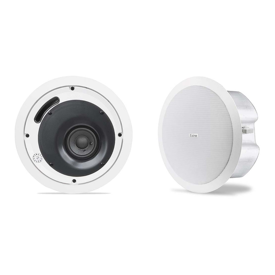
SI 3CT LP
Ceiling Speaker
Cut material.
Side Terminal
Cover
c. Insert the conduit(s) into the knockout opening(s) and
secure the conduit to the cover with the locking nut.
d. Pull the speaker wires from the conduit, strip 0.2
from the wire ends (do not tin the wires), and secure the
wires into the 4-pole captive screw connector. To connect
speakers in parallel, see the wiring diagram below.
Speaker 1
Power Amplifier
e. Bring the speaker up to the bottom of the hole in the
ceiling.
f. Plug the wired connector from step 3d into the speaker's
audio input connector. Secure the top terminal cover
with the two top screws that were loosened in step 3a;
hook the side terminal cover to the top terminal cover; and
secure the side terminal cover in place with the screw that
was loosened in step 2.
4-pole Captive
Screw Connector
N Installation in a plenum-rated environment
requires a wire gauge of 14 AWG to 18 AWG.
Front View of Input Terminal
70 V To Speakers
Speaker 2
Speaker 3
See NOTE below.
Top Terminal
Cover
Side Terminal
Cover
4-pole Captive
Screw Connector
LOOP IN
IN
LOOP
68-1263-01 Rev. B
(5 mm)
"
09 07
1
Advertisement

Related Manuals for Extron electronics SI 3CT LP


Summary of Contents for Extron electronics SI 3CT LP
- Page 1 SI 3CT LP Ceiling Speaker User’s Guide Frame Construction Ceiling Installation Take the cutout template from the packaging box and c. Insert the conduit(s) into the knockout opening(s) and punch out along the larger perforated circle. Place the secure the conduit to the cover with the locking nut.
- Page 2 SI 3CT LP Ceiling Speaker User’s Guide Frame Construction Ceiling Installation, Suspended Ceiling Installation cont’d Remove the ceiling tile where the speaker is to be installed. Loosen the four screws on the front baffle (counter clockwise) 1/2 turn. Insert the speaker in the ceiling hole, Cut the hole in the tile (see step 1 on page 1).
-
Page 3: Specifications
SI 3CT LP Ceiling Speaker User’s Guide Painting the Speaker Baffle Specifications Tear along the smaller perforated line of the cutout Acoustic & Electrical template marked as a paint shield. Push it into the front Speaker type......... Low profile ceiling speaker with metal back can baffle of the speaker.
Need help?
Do you have a question about the SI 3CT LP and is the answer not in the manual?
Questions and answers