Table of Contents
Advertisement
FL-8 Owner's Manual
CONTENTS
Founded in 1965, Vexilar, Inc. has a long his-
tory of bringing revolutionary technology to
the sport fishing industry. Just some of the
Vexilar firsts include: the first liquid crystal
display, the first fish alarm, the first three
color display, and the first CRT and straight
line paper graphs, for the sport fisherman.
1
2
3
4
4
5 - 8
9 - 10
10 - 14
15
16 - 20
21
22
23-25
26
Advertisement
Table of Contents

Related Manuals for VEXILAR FL-8


Summary of Contents for VEXILAR FL-8
-
Page 1: Table Of Contents
Transducer Beam Angle Chart Transducers 23-25 Service and Support Founded in 1965, Vexilar, Inc. has a long his- tory of bringing revolutionary technology to the sport fishing industry. Just some of the Vexilar firsts include: the first liquid crystal display, the first fish alarm, the first three color display, and the first CRT and straight line paper graphs, for the sport fisherman. -
Page 2: General Description
The FL-8 also has an alarm, which can alert you to fish or shallow water. The user controls this alarm so that anything that appears above a specific depth will sound the alarm. -
Page 3: Specifications
SPECIFICATIONS * Operating Voltage 10.5 - 15 Volts (12 Volts Nominal) * Current Draw: 250mA * Power Output: 400 Watts (Peak to Peak) * Frequency: 200 Khz * Resolution: 530 Segments * Target Separation: 2.65" Min. * Display Colors: 3 - Red, Orange, and Green * Dimensions: 4.4"H x 6"W x 2.5"D * Weight:... -
Page 4: Unit Installation
UNIT INSTALLATION To make the FL-8 work, you must provide the unit with power and mount the transducer in an appropriate location. UNIT INSTALLATION Find a convenient place to mount the unit. This may include a boat seat, deck, dash, or a portable case. -
Page 5: Transducer Installation
TRANSDUCER INSTALLATION There are three basic types of transducers to consider: High Speed, Puck Style and the Ice-Ducer System. HIGH SPEED TRANSDUCERS High Speed transducers designed to be mounted on the tran- som of a boat. The wedged shape will cut the water and give a clear depth reading at any boat speed. - Page 6 PUCK STYLE TRANSDUCERS There are three ways in which a Puck Style transducer can be mounted. It can be mounted In- Hull, on an electric trolling motor, or portable (with a suction cup or on an arm of some type). IN-HULL MOUNTING This method, gluing the transducer to the hull, gets the same results as if you were using the High Speed transducer only there are...
- Page 7 PUCK STYLE TRANSDUCERS There are three ways in which a Puck Style transducer can be mounted. It can be mounted In-Hull, on an electric trolling motor, or portable (with a suction cup or on an arm of some type). IN-HULL MOUNTING This method, gluing the transducer to the hull, gets the same results as if you were using the High Speed transducer only there are no holes to drill in the boat and there is no transducer on the transom...
- Page 8 THE ICE-DUCER SYSTEM* The Ice-Ducer system provides a quick and easy way to set up the trans- ducer for ice fishing. All of the adjust- ment needed to find the true perpendicu- lar point is done automatically. To use the Ice-Ducer, simply adjust the transducer to the desired depth and drop the assembly in the ice hole.
-
Page 9: Power And Range Control
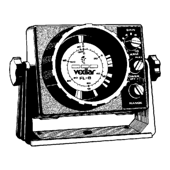
OPERATION Figure I shows the three main controls of the FL-8. They include Power and Range control, Gain, and Alarm Calibration. POWER AND RANGE CONTROL The knob located at the bottom of the control panel turns the unit on and selects which range is to be used. The center position is the Off position. -
Page 10: Alarm Calibration Control
TYPICAL INDICATIONS The three color display on the FL-8 can give you a lot of informa- tion if you know how to read it. A color represents the strength of a signal. A red color indicates a strong signal, an orange color indicat- ed a medium strength signal, and green represents a weak signal. - Page 11 HARD BOTTOM Under these conditions the bottom will be almost all red, although you will always see some orange and green at the trailing edge, as in figure J. A sharp red leading edge tells you that the bottom is very clean.
-
Page 13: Seeing Fish
SEEING FISH The FL-8 sees a fish as a target, much like the bottom. It has a leading edge, a width, and color content. Refer, again, to figure J. If the range setting is S x2 then the fish is just over 22 feet above the bot- tom. - Page 14 ICE FISHING Ice fishing brings out the best in the FL-8. The stable platform of ice lets you concentrate on your bait and the fish around it. The bot- tom becomes less important because it never changes. The only movement on the display is of your bait and fish.
-
Page 15: Maintenance
MAINTENANCE PERMANENT MOUNT With permanent mount applications, the power cord is left con- nected to the source, the transducer is not easily removed, and the gimbal bracket is screwed to the seat, deck, or dash. Under these con- ditions maintenance is very simple because nothing changes once the unit is installed. -
Page 16: Operational Questions & Answers
OPERATIONAL QUESTIONS & ANSWERS Where Should The Gain Control Be Set? For ice fishing - the gain control should be set so the bait you are fishing with is shown in green color on the dial. This color should be set while the lure or bait is at the normal fishing depth. - Page 17 How Long Will My Battery Last On The FL-8? Run Time - The FL-8 draws about 250 mA, less than a quarter of an amp of current The unit will run good until the battery voltage drops to about 10 volts.
- Page 18 By extending the transducer to the bottom of the hole this ringing can be eliminated. Will The FL-8 Read Through The Ice? YES! It will easily read through ice, provided the ice is CLEAR ICE and not MILKY ICE.
- Page 19 Plastic or wood transducer arms cause little problems. To test your portable box system, in air, turn the FL-8 on, range 1, and with the gain control turned to maximum posi- tion, note the width of the zero indication. If the zero indication is...
- Page 20 your hand. While squeezing, if the zero gets smaller you need to work on the transducer attachment. To solve the problem, especially with a metal transducer arm, remove the transducer from the metal arm. Then tape three layers of black electrical tape around the arm in the flat section of the arm, then lay the transducer against the tape and continue to tape it onto the flat section on the metal arm.
-
Page 21: Trouble Shooting Chart
Trouble Shooting Chart... -
Page 22: Transducer Beam Angle Chart
Transducer Beam Angle Verses Diameter of Coverage... - Page 23 Speed Transducer. Comes with the Mounting Bracket and 25 Feet of Cable. TK144 Complete Mounting Kit. Comes with TB0044 Transducer, FL-8 Power Cord, Unit Mounting Bracket, and all the Hardware You Need to do the Job Right. TB0030 9 Degree Transom Mount High Speed Transducer. Comes with the Mounting Bracket and 25 Feet of Cable.
-
Page 24: Transducers
Feet of Cable. TK123 Complete Mounting Kit. Comes with TB0023 Transducer, FL-8 Power Cord, Unit Mounting Bracket, and all the Hardware You Need to do the Job Right. BK0023 Optional Suction Cup Mount for TB0023. TB0027 9 Degree Puck Transducer. For Mounting on a Electric Trolling Motor, In-Hull Mounting, Portable Use, or Ice Fishing. - Page 25 Finder. "S" CABLE The S-Cable (short for Suppression Cable) is used to reduce the output power of the FL-8 or FL-8SLT. This can often help clear up readings in shallow or cluttered waters. Simple installation between the unit and transducer.
-
Page 26: Service And Support
Be sure to read the Question and Answer and Trouble Shooting sections first. * Address Vexilar, Inc. 200 W. 88th St. Minneapolis, MN, 55420-2752 * Telephone (952) 884-5291 (8 am to 5 pm M-F Central)
Need help?
Do you have a question about the FL-8 and is the answer not in the manual?
Questions and answers