Harman Kardon AVR 330 Owner's Manual
Harman/kardon avr 330 audio/video receiver owner's manual
Hide thumbs
Also See for AVR 330:
- Brochure & specs (18 pages) ,
- Service manual (135 pages) ,
- Owner's manual (61 pages)

Related Manuals for Harman Kardon AVR 330


Summary of Contents for Harman Kardon AVR 330
- Page 1 Power for the Digital Revolution AVR 330 AUDIO/VIDEO RECEIVER OWNER’S MANUAL DIGITAL LOGIC 7 PRO LOGIC 3 STEREO 5 CH. STEREO SURR. OFF ® ® VID 1 VID 2 VID 3 FMAM VID 4 TAPE 68CH...
-
Page 2: Table Of Contents
AVR 330 AUDIO/VIDEO RECEIVER Introduction Safety Information Unpacking Front-Panel Controls Rear-Panel Connections Main Remote Control Functions Zone II Remote Control Functions Installation and Connections System Configuration Speaker Placement System Setup Input Setup Surround Setup Speaker Setup Delay Settings Output Level Adjustment... -
Page 3: Introduction
Complete volume control in the second zone is possible with a separate infrared con- trol link. To make it easy to operate the AVR 330 from a remote zone, a separate “Zone II” remote is included. The AVR 330’s powerful amplifier uses traditional... -
Page 4: Safety Information
Do not obstruct the ventilation slots on the top of the unit, or place objects directly over them. Due to the weight of the AVR 330 and the heat generated by the amplifiers, there is the remote possibility that the rubber padding on the bottom of the unit’s feet may leave marks on certain... -
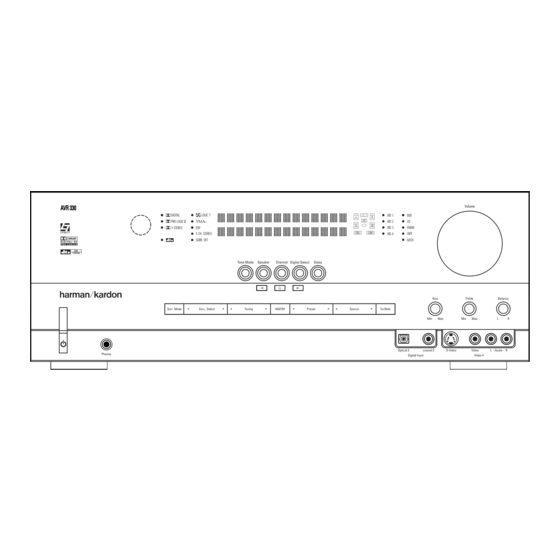
Page 5: Front-Panel Controls
Ô Video 4 Audio Input Jacks Bass Control AVR 330; press it again to turn the unit off. The Power Indicator 3 turns blue when the unit is on. 4 Headphone Jack: This jack may be used to listen to the AVR 330’s output through a pair of headphones. - Page 6 @ Set Button: When making choices during the setup and configuration process, press this button to enter the desired setting into the AVR 330’s memory. # Digital Input Selector: Press this button to select one of the digital inputs or the analog input for any source.
-
Page 7: Rear-Panel Connections
£ Tape Outputs: Connect these jacks to the RECORD/INPUT jacks of an audio recorder. ¢ Remote IR Input: If the AVR 330’s front-panel IR sensor is blocked due to cabinet doors or other obstructions, an external IR sensor may be used. - Page 8 (white for front left and red for front right) (+) terminals on the AVR 330 to the red (+) terminals on the speakers and the black (–) terminals on the AVR 330 to the black (–) terminals on the speakers.
- Page 9 Video 1 Audio/Video Inputs: Connect the com- posite video and L/R analog audio PLAY/OUT jacks of a VCR or other video source to these jacks. Video 1 Audio/Video Outputs: Connect the composite video and L/R analog audio REC/IN jacks of a VCR or other video recording device such as a DVD recorder or PVR to these jacks.
-
Page 10: Main Remote Control Functions
EzSet Sensor Microphone NOTE: • The function names shown here are each button’s feature when used with the AVR 330. Most buttons have additional functions when used with other devices. See pages 39–40 for a list of these functions. • To make it easier to follow the instructions that refer to... - Page 11 AVR Selector: Pressing this button will switch the remote so that it will operate the AVR 330’s functions. If the AVR 330 is in the Standby mode, it will also turn the AVR 330 on. g AM/FM Tuner Select: Press this button to select the AVR 330’s tuner as the listening choice.
- Page 12 Disc Skip Button: This button has no direct function for the AVR 330 but is most often used to change to the next disc in a CD or DVD player when the remote is programmed for that type of device.
- Page 13 Channel Direct Input j as the audio source. Mute: Press this button to momentarily silence the AVR 330 or TV set being controlled, depending on which device has been selected. When the AVR 330 remote is being programmed to operate another device, this button is pressed with the Input Selector Button e to begin the programming process.
-
Page 14: Zone Ii Remote Control Functions
NOTES: • The Zone II remote may be used in either the same room where the AVR 330 is located, or it may be used in a separate room with an optional infrared sensor that is connected to the AVR 330’s Multiroom IR Input ∞... -
Page 15: System Installation
Digital Audio Inputs dg*(. 4. Connect the coaxial or optical Digital Audio Outputs ab on the rear panel of the AVR 330 to the matching digital input connections on a CD-R or MiniDisc recorder. 5. Assemble the AM Loop Antenna supplied with the unit so that the tabs at the bottom of the antenna loop snap into the holes in the base. -
Page 16: System And Power Connections
Multiroom IR Link The remote room IR receiver should be connected to the AVR 330 via standard coaxial cable. Plug the IR con- nection cable into the Multiroom IR Input ∞ jack on the AVR 330’s rear panel. -
Page 17: System Configuration
You are now ready to power up the AVR 330 to begin these final adjustments. 1. Make certain that the AC power cord ‡ is firmly inserted into an unswitched AC outlet. -
Page 18: Input Setup
“burned into” the projection tubes, plasma screen or CRT. This type of damage is not covered by the AVR 330 warranty and may not be cov- ered by the projector/TV set’s warranty. The AVR 330 has two on-screen display modes, “Semi-OSD”... -
Page 19: Surround Setup
– you may change it later. However, to make it easier to establish the initial parameters for the AVR 330, it is best to select Dolby Pro Logic II or Logic 7 for most analog inputs and Dolby Digital for inputs connected to digital sources. -
Page 20: Speaker Setup
BACK TO MASTER MENU line and press the Set Button p. Speaker Setup This menu tells the AVR 330 which type of speakers are in use. This is important as it adjusts the settings that decide whether your system will use the “5-chan- nel”... - Page 21 When this option is selected, all bass information will be routed to the front left/right “main” speakers. • If a subwoofer is connected to the AVR 330, you have the option to have the front left/right “main” speakers reproduce bass frequencies at all times,...
-
Page 22: Delay Settings
To avoid problems, we recommend that delay times be adjusted using the Dolby Digital mode. If a different mode is selected at a later time, the AVR 330 will automatically restrict the delay settings to those required by the surround mode in use. -
Page 23: Output Level Adjustment
Output level adjustment is a key part of the configura- tion of any surround sound product. It is particularly important for a digital receiver such as the AVR 330, as correct outputs ensure that you hear soundtracks with the proper directionality and intensity. -
Page 24: Manual Output Level Adjustment
¯. If the sound from a speaker location does NOT match the position indicated in the display, turn the AVR 330 off using the Main Power Switch 1 and check the speaker wiring or connections to external power amplifiers to make certain that each speaker is connected to the correct output terminal. -
Page 25: Channel/8-Channel Direct Input
Turning the AVR 330 On or Off • When using the AVR 330 for the first time, you must press the Main Power Switch 1 on the front panel to turn the unit on. This places the unit in a Standby mode, as indicated by the amber color of the Power Indicator 2 . -
Page 26: Surround Mode Selection
(HDTV) system. An optional, external RF demodulator is required to use the AVR 330 to listen to the Dolby Digital sound- tracks available on laser discs. Connect the RF output of the LD player to the demodulator and then connect the digital output of the demodulator to the Optical or Coaxial Inputs *(dg of the AVR 330. -
Page 27: Surround Mode Chart
Surround Mode Chart MODE FEATURES Dolby Digital Available only with digital input sources encoded with Dolby Digital data. It provides up to five separate main audio channels and a special dedicated low-frequency effects (LFE) channel. Dolby Digital EX Available when the receiver is configured for 6.1/7.1-channel operation, Dolby Digital EX is the latest version of Dolby Digital. When used with movies or other programs that have special encoding, Dolby Digital EX reproduces specially encoded soundtracks so that a full 6.1/7.1 sound field is available. - Page 28 Dolby Pro Logic II or Logic 7. Since the range of available surround modes is dependent on the type of digital data that is present, the AVR 330 uses a variety of indicators to let you know what type of signal is present.
-
Page 29: Digital Inputs
AVR 330. It is also possible for the type of signal feed to change during the course of a DVD playback. In some cases, the previews of special material will only be recorded in 2.0 audio, while the main feature is available in 5.1 audio. -
Page 30: Tape Recording
Repeat the procedure as needed until all channels requiring adjustment have been set. When all adjust- ments have been made and no further adjustments are made for five seconds, the AVR 330 will return to normal operation. The channel output for any input may also be adjusted using the full-OSD on-screen menu system. -
Page 31: Advanced Features
Turn-On Volume Level As is the case with most audio/video receivers, when the AVR 330 is turned on, it will always return to the volume setting in effect when the unit was turned off. However, you may prefer to always have the AVR 330 turn on at a specific setting, regardless of what was last in use when the unit was turned off. -
Page 32: Full-Osd Time-Out Adjustment
This setting is temporary and will remain active only until it is changed or until the AVR 330 is turned off. Once the unit is turned off, the semi-OSD displays will remain activated, even if they were switched off for the previous listening session. -
Page 33: Multiroom Operation
Selector buttons to turn on to a specific source. As long as an IR feed to the AVR 330 has been established from the remote room, using any of the buttons on either remote will control the remote loca- î, change the tuner frequency... -
Page 34: Multiroom Operation
MULTIROOM OPERATION Once the Multiroom system is turned on, it will remain on even if the AVR 330 is placed in the Standby mode in the main room by pressing the Power Off Button a on the remote or the Standby/On Button 3 on the front panel. -
Page 35: Programming The Remote
Auto Search Method. Auto Search Method If the unit you wish to include in the AVR 330’s remote is not listed in the code tables in this manual or if the code does not seem to operate properly, you may wish... -
Page 36: Programmed Device Functions
Function List and then look in the column for the device you are controlling. For example, button number 46 is the Direct button for the AVR 330, but it is the “Favorite” button for many cable television boxes and satellite receivers. Button number 32 is the Delay button for the AVR 330, but the Open/Close button for CD players. -
Page 37: Volume Punch-Through
TV viewing, you may wish to have the AVR 330’s volume activated, although the remote is set to run the TV. Either the AVR 330 or TV volume control may be associated with any of the remote’s devices. -
Page 38: Resetting The Remote Memory
PROGRAMMING THE REMOTE Example: To use the TV button to operate a sec- ond VCR, first press the TV Input Selector e and the Mute Button at the same time until the red light glows under the TV Button e. Press the VCR Button e, followed by the three-digit code for the specific model you wish to control. -
Page 39: Function List
No. Button Name AVR Function Power On Power On Power On Power Off Power Off Power Off Mute Mute Mute AVR Select DVD Input Select DVD Select CD Input Select Tape Tape Input Select VID 1 Video 1 Select VID 2 Video 2 Select 10 VID 3 Video 3 Select... - Page 40 FUNCTION LIST No. Button Name AVR Function 45 Tune Up Tune Up Next Chapter Track Direct 46 Direct Direct Tuner Entry Angle 47 Clear Clear Clear 48 Preset Up Preset Tune Up Slow Forward +10 49 Tune Down Tune Down Prev Chapter Track Increment 50 OSD 51 D.
-
Page 41: Setup Code Tables
Manufacturer/Brand Setup Code Number AIWA A MARK ADMIRAL AKAI AMPRO ANAM BLAUPUNKT BROKSONIC CANDLE CAPEHART CENTURION CENTRONIC CITIZEN CLASSIC CONCERTO CONTEC CORANDO CORONADO CRAIG CROWN CURTIS MATHES DAEWOO DAYTRON DIGI LINK DYNASTY DYNATECH ELECTROHOME EMERSON FUNAI FUTURETECH GOLD STAR/LG GRUNDIG HALL MARK HARMAN KARDON HITACHI... - Page 42 SETUP CODE TABLE: TV Manufacturer/Brand Setup Code Number LOGIK LUXMAN MAGNAVOX MARANTZ MATSUI MEMOREX METZ MINERVA MITSUBISHI NATIONAL NIKEI ONKING ONWA OPTONICA ORION PANASONIC PHILCO PHILIPS PIONEER PORTLAND PROSCAN PROTON QUASAR RADIO SHACK REALISTIC RUNCO SAMPO SAMSUNG SANYO SCOTT SEARS SHARP SIEMENS SIGNATURE...
- Page 43 Manufacturer/Brand Setup Code Number TEKNIKA TELERENT TERA THOMSON TOSHIBA TOTEVISION VIDEO CONCEPTS VIDTECH WARDS YAMAHA YORK YUPITERU ZENITH ZONDA SETUP CODE TABLE: TV SETUP CODES...
- Page 44 SETUP CODE TABLE: VCR Manufacturer/Brand Setup Code Number AIWA AKAI 048 108 109 126 AMPRO AUDIO DYNAMICS 018 048 BROKSONIC 110 147 CANDLE 134 135 CANON 135 140 CAPEHART CITIZEN CRAIG 045 116 DAEWOO 017 094 104 DAYTRON 018 048 DYNATECH EMERSON 013 040 042 110 112...
- Page 45 Manufacturer/Brand Setup Code Number SALORA SAMSUNG 045 051 095 105 109 SANSUI 048 116 147 SANYO 017 020 SCOTT 110 112 SEARS 017 020 SHARP 129 156 SONY 080 129 SOUNDESIGN SYLVANIA SYMPHONIC TANDY 017 040 TASHICO TATUNG TEAC 040 048 TEKNIKA THOMAS TiVo...
- Page 46 SETUP CODE TABLE: CD Manufacturer/Brand Setup Code Number ADCOM AIWA 156 170 AKAI AUDIO TECHNICA AUDIOACCESS AUDIOFILE CALIFORNIA AUDIO CAPETRONIC CARRERA CARVER 143 144 CASIO CLARINETTE DENON EMERSON FISHER FRABA FUNAI GENEXXA GOLD STAR/LG HAITAI HARMAN KARDON 054 190 HITACHI INKEL JC PENNEY JENSEN...
- Page 47 Manufacturer/Brand Setup Code Number REALISTIC 104 105 SANSUI 157 172 SANYO SCOTT SHARP 151 159 SHERWOOD 105 133 SONY 118 132 SOUNDSTREAM SYMPHONIC TAEKWANG TEAC 086 106 THETA DIGITAL TOSHIBA 151 155 VECTOR RESEARCH VICTOR WARDS YAMAHA 061 135 YORK SETUP CODE TABLE: CD 108 164 166 167 180 181...
- Page 48 SETUP CODE TABLE: DVD Manufacturer/Brand Setup Code Number APEX DIGITAL DENON 019 051 003 004 GOLD STAR/LG HARMAN KARDON 005 055 064 066 MAGNAVOX MARANTZ MITSUBISHI ONKYO 009 048 PANASONIC 024 030 044 PHILIPS PIONEER 041 065 PROCEED PROSCAN 003 004 003 004 SAMSUNG 053 054...
- Page 49 Manufacturer/Brand Setup Code Number ALPHASTAR ALPHASTAR DBS ALPHASTAR DSR BIRDVIEW CHANNEL MASTER 320 321 CHAPARRAL 315 316 CITOH DRAKE 313 317 413 481 DX ANTENNA 331 352 379 483 ECHOSTAR 395 397 453 463 ELECTRO HOME FUJITSU 324 329 GENERAL INSTRUMENT 303 311 365 403 HITACHI DBS...
- Page 50 SETUP CODE TABLE: TAPE Manufacturer/Brand Setup Code Number HARMAN KARDON SETUP CODE TABLE: CBL Manufacturer/Brand Setup Code Number 001 011 ALLEGRO AMERICAST ARCHER BELCOR CABLE STAR 033 113 CITIZEN COLOUR VOICE 085 090 DIGI EAGLE EASTERN 066 070 ELECTRICORD EMERSON FOCUS G.I.
- Page 51 Manufacturer/Brand Setup Code Number REMBRANT SAMSUNG 072 186 SCIENTIFIC ATLANTA 183 203 221 222 SEAM SIGNATURE 001 188 SPRUCER 053 081 177 189 STARCOM 002 011 163 STARGATE TANDY TELECAPATION TEXSCAN TIMELESS TOCOM 170 205 UNITED CABLE UNIVERSAL 033 034 039 042 113 VIDEOWAY 124 211 VIEWSTAR...
-
Page 52: Troubleshooting Guide
If the system still malfunctions, a sys- tem reset may clear the problem. To clear the AVR 330’s entire system memory includ- ing tuner presets, output level settings, delay times and speaker configuration data, press and hold the Tone Mode Button 5 buttons for three seconds. -
Page 53: Technical Specifications
Distortion Mono/Stereo 0.2/0.3% Stereo Separation 40dB @ 1kHz Selectivity ±400kHz, 70dB Image Rejection 80dB IF Rejection 90dB AVR 330 TECHNICAL SPECIFICATIONS AM Tuner Section Frequency Range Signal-to-Noise Ratio Usable Sensitivity Distortion Selectivity Video Section Television Format Input Level/Impedance Output Level/Impedance... - Page 54 NOTES NOTES...
- Page 55 NOTES NOTES...
- Page 56 ® 250 Crossways Park Drive, Woodbury, New York 11797 www.harmankardon.com © 2003 Harman International Industries, Incorporated Part No. CQX1A851Z...
Need help?
Do you have a question about the AVR 330 and is the answer not in the manual?
Questions and answers