Mitsubishi Electric Mr. Slim MS09TW Service Manual
Wireless type models
Hide thumbs
Also See for Mr. Slim MS09TW:
- Operating insructions (26 pages) ,
- Operating instructions manual (15 pages)
Table of Contents
Advertisement
Quick Links
SPLIT-TYPE AIR CONDITIONERS
SERVICE MANUAL
Wireless type
Models
MS09TW
MS12TN
MS15TN
MS17TN
MS12TN
MS15TN
MS17TN
INDOOR UNIT
MU15TN
MU17TN
OUTDOOR UNIT
· MU09TW
(W)
· MU12TN
(W)
· MU15TN
(W)
· MU17TN
(W)
Remote
controller
C
CONTENTS
1. FEATURES ············································OB274-2
2. TECHNICAL CHANGES ························OB274-3
3. PART NAMES AND FUNCTIONS ········OB274-4
4. SPECIFICATIONS··································OB274-7
5. DATA ····················································OB274-10
6. OUTLINES AND DIMENSIONS ··········OB274-16
7. WIRING DIAGRAM ······························OB274-18
8. REFRIGERANT SYSTEM DIAGRAM··OB274-21
10. SERVICE FUNCTIONS ························OB274-31
11. TROUBLESHOOTING ··························OB274-33
12. DISASSEMBLY INSTRUCTIONS ········OB274-42
13. PARTS LIST ········································OB274-51
14. OPTIONAL PARTS ······························OB274-57
The Slim Line.
From Mitsubishi Electric.
R
R
No. OB274
TM
Advertisement
Table of Contents

Related Manuals for Mitsubishi Electric Mr. Slim MS09TW


Summary of Contents for Mitsubishi Electric Mr. Slim MS09TW
-
Page 1: Table Of Contents
7. WIRING DIAGRAM ······························OB274-18 8. REFRIGERANT SYSTEM DIAGRAM··OB274-21 9. MICROPROCESSOR CONTROL ········OB274-23 10. SERVICE FUNCTIONS ························OB274-31 11. TROUBLESHOOTING ··························OB274-33 12. DISASSEMBLY INSTRUCTIONS ········OB274-42 13. PARTS LIST ········································OB274-51 MU15TN 14. OPTIONAL PARTS ······························OB274-57 MU17TN OUTDOOR UNIT The Slim Line. From Mitsubishi Electric. -
Page 2: Features
It has a liquid crystal display which indicates such information as mode, fan speed and temperature selected as well as the programmed ON/OFF timer. It is also equipped with “I Feel Control”, a unique Mitsubishi Electric fea- ture that allows the user to adjust the temperature to exactly the level he or she wants simply by tapping the button that describes present conditions : “Too Cool”... -
Page 3: Technical Changes
TECHNICAL CHANGES MS09NW2 MS09TW 1. Indoor unit has changed 2. Remote controller has changed. MS12NN2 MS12TN 1. Remote controller has changed. 2. Union size of connect pipe for gas has changed. MS15NN2 MS15TN MS17NN2 MS17TN 1. Remote controller has changed. -
Page 4: Part Names And Functions
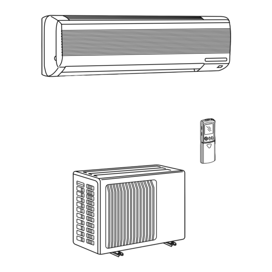
PART NAMES AND FUNCTIONS INDOOR UNIT MS09TW MS12TN MS15TN Grille MS17TN Deodorizing filter(option) Air inlet (gray sponge type) Air cleaning filter(option) (white bellows type) Remote control receiving section Front panel Horizontal vane Air filter Vertical vanes Remote controller Operation section... - Page 5 OUTDOOR UNIT MU09TW MU15TN MU12TN MU17TN Air inlet Air inlet (back and side) (back and side) Piping Drain hose Air outlet Air outlet Drain outlet OB274-5...
-
Page 6: Remote Controller
REMOTE CONTROLLER MS09TW MS12TN Signal transmitting section MS15TN MS17TN Operation display section OPERATE /STOP (ON /OFF)button ON/OFF WARM COOL TEMPERATURE buttons Open the front lid. CLOCK ON/OFF WARM COOL FAN SPEED CONTROL button STOP I FEEL COOL OFF-TIMER button VANE... -
Page 7: Specifications
SPECIFICATIONS Model MS09TW MS12TN Item Cooling capacity Btu/h 8,500 12,300/12,600 Power consumption 1,100/1,130 [SEER] 10.1 [10.2] 11.2/11.2 [11.3/11.3] INDOOR UNIT MODEL MS09TW MS12TN External finish White Power supply V, phase, Hz 115, 1, 60 Max. fuse size (time delay)/ Disconnect switch Min. - Page 8 MS15TN MS17TN Item Model Cooling capacity Btu/h 14,300/14,600 15,900/16,100 Power consumption 1,370/1,400 1,570/1,600 [SEER] 10.4/10.4 (10.5/10.5) 10.1/10.1 (10.2/10.2) INDOOR UNIT MODEL MS15TN MS17TN External finish White Power supply V, phase, Hz 115, 1, 60 Max. fuse size (time delay)/Disconnect switch Min.
- Page 9 Model Max. length : ft. Minimum Minimum Indoor unit Outdoor unit Outside Outside Wall Wall diameter diameter thickness thickness MS09TW [ 3/8 MU09TW 0.0285 MS12TN [ 1/2 Gas : 16-15/16 Gas : MU12TN [ 1/4 0.0265 MS15TN Liquid : 19-11/16...
-
Page 10: Data
DATA 5-1. PERFORMANCE DATA 1) COOLING CAPACITY MS09TW MS12TN MS15TN MS17TN MU09TW MU12TN MU15TN MU17TN (115V) Outdoor intake air DB temperature ( ˚F ) Indoor air Model ( ˚F ) 10.4 0.75 0.82 0.88 0.93 0.97 MS09TW 0.71 0.78 0.84 0.89... - Page 11 5-2. PERFORMANCE CURVE NOTE : A point on the curve shows the reference point. Curves in graph of MS(MU)12/15/17TN shows curves under 230V AC. As for curves under 208V AC, refer to PERFORMANCE DATA on page 10. MS09TW MS12TN Cooling Cooling SHF at rating condition = 0.70...
- Page 12 5-3. Condensing pressure Data is based on the condition of indoor humidity 50%. Air flow should be set at High. A point on the curve shows the reference point. MU09TW (PSIG) (PSIG) 100 104( F) 104( F) Outdoor ambient temperature Outdoor ambient temperature MU12TN (PSIG)
- Page 13 Data is based on the condition of indoor humidity 50%. Air flow should be set at High. A point on the curve shows the reference point. MU15TN (PSIG) (PSIG) 68 70 100 104( F) 68 70 100 104( F) Outdoor ambient temperature Outdoor ambient temperature MU17TN (PSIG)
-
Page 14: Standard Operation Data
5-4. STANDARD OPERATION DATA Model MS09TW MS12TN MS15TN MS17TN Item Unit Cooling Cooling Cooling Cooling Capacity Btu / h 8,500 12,300/12,600 14,300/14,600 15,900/16,100 Total — 0.70 0.71 0.65 0.65 Input 0.84 1.10/1.13 1.37/1.40 1.57/1.60 INDOOR UNIT MODEL MS09TW MS12TN MS15TN... - Page 15 5-5. OPERATING RANGE (1) POWER SUPPLY Rating Guaranteed Voltage Model MS09TW MS12TN Indoor unit Max. 127V Min. 103V 115V MS15TN 115V 60Hz 1[ MS17TN MU09TW MU12TN Min. 198V 208V 230V Max. 253V Outdoor unit MU15TN 208/230V 60Hz 1[ MU17TN (2) OPERATION...
-
Page 16: Outlines And Dimensions
OUTLINES AND DIMENSIONS Unit : inch MS09TW 3-5/16 6-5/8 Installation plate INDOOR UNIT Indoor unit 32-3/16 3-1/4 12-13/16 12-13/16 4-5/8 Wall hole [2-9/16 3/16 33-1/2 7-7/16 Installation plate Liquid line [1/4 19-11/16 Gas line [3/8 16-15/16 Insulation [1-7/16 O.D Air in [13/16 I.D... - Page 17 MS12TN MS15TN MS17TN Unit : inch 4holes 7/16 O 13/16 Indoor unit INDOOR UNIT 5-7/8 25-1/2 8-9/16 39-3/16 17-11/16 17-11/16 17-1/4 13-7/8 Wall hole [2-15/16 Installation plate 39-15/16 7-1/2 3/16 Installation plate Liquid line [ 5/16 19-11/16 Gas line [1/2 16-15/16 Air in Insulation [ 1-15/16 O.D [ 1-1/8 I.D...
-
Page 18: Wiring Diagram
WIRING DIAGRAM MS09TW MODEL WIRING DIAGRAM INDOOR UNIT CN202 TO OUTDOOR RT12 UNIT HIC1 CONNECTING RT11 WIRES 12V DC CN201 FROM OUTDOOR NR11 UNIT CONNECTING WIRES TRANS POWER SUPPLY SR141 TAB12 115V 1 phase CN211 60Hz LD101T ELECTRONIC CONTROL P.C. BOARD... - Page 19 MS12TN MS15TN MS17TN MODELS WIRING DIAGRAM INDOOR UNIT TO OUTDOOR RT12 UNIT CONNECTING CN201 WIRES HIC1 RT11 12V DC LDCOM FROM OUTDOOR LDC11 UNIT CONNECTING LDC12 TAB12 WIRES LDFH SR144 POWER TRANS LDFL SUPPLY SR142 LDFM 115V SR143 1 phase CN202 60Hz ELECTRONIC CONTROL P.C.
- Page 20 MU15TN MU17TN MODELS WIRING DIAGRAM OUTDOOR UNIT GRN/YLW GROUND POWER SUPPLY 208/230V 1phase 60Hz FROM INDOOR UNIT CONNECTING WIRES 115V 1 Phase 60Hz FROM INDOOR UNIT CONNECTING WIRES 12V DC FROM INDOOR UNIT CONNECTING WIRE SYMBOL NAME SYMBOL NAME SYMBOL NAME COMPRESSOR CAPACITOR OUTDOOR FAN MOTOR (INNER PROTECTOR)
-
Page 21: Refrigerant System Diagram
REFRIGERANT SYSTEM DIAGRAM Unit:inch MU09TW MS09TW INDOOR UNIT OUTDOOR UNIT Refrigerant pipe (option) (with heat insulator) Stop valve with service port Fusible plug Indoor heat Outdoor heat Indoor coil Flared Service Service exchanger thermistor exchanger connection port port RT12 Compressor... - Page 22 MS15TN MU15TN MS17TN MU17TN OUTDOOR UNIT INDOOR UNIT Refrigerant pipe (option) (with heat insulator) Stop valve with service port Indoor coil Indoor heat thermistor Outdoor heat RT12 exchanger Service Service Flared exchanger Fusible plug port port connection Distributor Accumulator Room temperature thermistor Muffler RT11...
-
Page 23: Microprocessor Control
MICROPROCESSOR CONTROL MU09TW MS09TW MU12TN MS12TN MS15TN MU15TN MU17TN MS17TN Once the operation mode are set, the same operation mode can be repeated by simply turning the OPERATE/STOP(ON/OFF) button ON. Indoor unit receives the signal with a beep tone. When the system turns off, 3-minute time delay will operate to protect system from overload and compressor will not restart for 3 minutes. - Page 24 9-1. “I FEEL CONTROL” OPERATION Initial room temperature mode (1) Press OPERATE/STOP(ON/OFF) button on the remote con- troller. OPERATION INDICATOR lamp of the indoor unit will COOL mode of more than 77-F “I FEEL CONTROL” turn on with a beep tone. (2) Press OPERATION SELECT button to set “I FEEL CONTROL”...
- Page 25 (5) TEMPERATURE buttons In “I FEEL CONTROL” mode, set temperature is decided by the microprocessor based on the room temperature. In addition, set temperature is controlled by TOO WARM or TOO COOL buttons when you feel too cool or too warm. Each time the TOO WARM or TOO COOL button is pressed, the indoor unit receives the signal and emits a beep tone.
- Page 26 —DRY mode of “I FEEL CONTROL”— The system for dry operation uses the same refrigerant circuit as the cooling circuit. The compressor and the indoor fan are controlled by the temperature. By such controls, amount of air flow of indoor unit will be reduced in order to lower humidity without much room tempera- ture drop.
- Page 27 9-3. DRY OPERATION (1) Press OPERATE/STOP(ON/OFF) button. OPERATION INDICATOR lamp of the indoor unit turns on with a beep tone. (2) Select DRY mode with the OPERATION SELECT button. (3) The microprocessor reads the room temperature and determines the set temperature. Set temperature is as shown on the right chart.
- Page 28 (3) Positioning The vane is once pressed to the vane stopper below to confirm the standard position and then set to the desired angle. Confirming of standard position is performed in case of follows. (a) When the OPERATE/STOP(ON/OFF) button is pressed. (POWER ON/OFF) (b) When the vane control is changed AUTO to MANUAL.
- Page 29 9-7. TIMER OPERATION 1. How to set the timer. (1) Press OPERATE/STOP(ON/OFF) button to start the air conditioner. (2) Check that the current time is set correctly. NOTE : Timer operation will not work without setting the current time. Initially “AM0:00” blinks at the current time display of TIMER MONITOR, so set the current time correctly with CLOCK SET button.
- Page 30 In case of latter normal operation will start. NOTE : Do not press the EMERGENCY OPERATION switch during normal operation. • The following indication applies regardless MS09TW of shape of the indicator. OPERATION INDICATOR lamp Press once <Cool>...
-
Page 31: Service Functions
SERVICE FUNCTIONS MS09TW MS12TN MS15TN MS17TN 10-1. TIMER SHORT MODE For service, set time can be shortened by short circuit of JPG and JPS the electronic control P.C. board. The time will be shortened as follows. (Refer to page 39 or 40.) - Page 32 10-3. AUTO RESTART FUNCTION When the indoor unit is controlled with the remote controller, the operation mode, the set temperature, and the fan speed are memorized by controlled the indoor electronic control P.C. board(MS09) the auto restart assembly(MS12/1517). When the main power is turned off and then turned back on, the unit restarts automatically in the memorized set conditions approximately after 3 minutes.
-
Page 33: Troubleshooting
TROUBLESHOOTING MS09TW MS12TN MS15TN MS17TN MU09TW MU12TN MU15TN MU17TN 11-1. Cautions on troubleshooting 1. Before troubleshooting, check the following: 1) Check the power supply voltage. 2) Check the indoor/outdoor connecting wire for mis-wiring. 2. Take care the following during servicing. - Page 34 11-2. Instruction of troubleshooting Start Indoor unit oper- <MS12/15/17> OPERATION INDICATOR Indoor unit Indoor unit doesn’t ates. Outdoor unit When the lamp on the indoor unit is doesn’t receive the signal doesn’t operate. remote controller flashing on and off. receive the from remote con- is pressed or signal from...
- Page 35 MS09TW MS12TN MS15TN MS17TN MU09TW MU12TN MU15TN MU17TN 2. Trouble criterion of main parts Part name Check method and criterion Figure Room Measure the resistance with a tester. temperature (Part temperature 50°F ~ 86°F) thermistor(RT11) Normal Abnormal Indoor coil Open or short-circuit 8k"...
-
Page 36: A Check Of Indoor Fan Motor
Check of indoor fan motor Turn OFF the power supply. Check connector (Fan motor) visually. Indoor fan does not operate. Is soldered point of the connector Are lead wires connected? correctly soldered? Re-connect the lead Re-solder it. wires. Disconnect lead wires from connector (Fan motor). Measure resistance between lead wires No.1 and No.3 and then No.2 and No.3 (MS09) No.1 and No.4 and then No.3 and No.4 (MS12/15/17) -
Page 37: Check Of Remote Controller And Receiver P.c. Board
Switch on the remote controller wIn case of replacing the receiver P.C. board of MS09TW, replace the indoor Is LCD display on remote con- electronic control P.C. board with it Replace the batteries.(Refer to page 33.) troller displayed? because they are unified. -
Page 38: Check Of Indoor Electronic Control P.c. Board
Check of indoor electronic control P.C. board The unit doesn’t operate with the remote controller. Also, the OPERATION INDICATOR lamp doesn’t light up by pressing the EMERGENCY OPERATION switch. Check the both “parts side” and “pattern side” of indoor electronic control P.C. board visually. - Page 39 TEST POINT DIAGRAM AND VOLTAGE MS09TW Indoor electronic control P.C. board Fuse 250V AC 3A Varistor(NR11) Fan motor Power supply input 115V AC – 12V DC Room temperature thermistor (RT11) Timer short mode point (JPS, JPG) (Refer to page 31.)
- Page 40 TEST POINT DIAGRAM AND VOLTAGE MS12TN MS15TN MS17TN Indoor electronic control P.C. board Fan motor Med. Low High 8 7 5 6 4 Varistor(NR11) Fuse 250V AC 3.0A CN201 Power supply input 115V AC 12V DC JP11 5V DC JP24 Auto restart function Disconnect the AUTO RESTART CN104...
- Page 41 RELAY OPERATION MS09TW MS12TN MS15TN MS17TN 1. COMPRESSOR CONTACTOR • EACH MODE MODE THERMOSTAT 52C CONTACTOR INDOOR FAN SPEED COOL & COOL mode AUTO or set speed of I FEEL CONTROL OFF for 2 min. AUTO or set speed after unit starts operation Repeat of 8 min.
-
Page 42: Disassembly Instructions
2Pull the terminal while pull out the terminal pushing the locking slowly. Locking lever lever. Connector 12-1. MS09TW INDOOR UNIT OPERATING PROCEDURE PHOTOS 1. Removing the front panel Photo 1 (1) Remove the screw caps at the bottom of the front panel. - Page 43 OPERATING PROCEDURE PHOTOS Photo 3 Screw of the ground wire 3. Removing the electrical box (1) Remove the front panel. (Refer to 1) (2) Remove the electrical cover. (Refer to 2) (3) Disconnect the connector of the indoor coil thermistor (CN112). (4) Disconnect the motor connector (CN211 and CN121) and the vane motor connector (CN151) on the electronic control P.C.
- Page 44 OPERATING PROCEDURE PHOTOS 5. Removing the line flow fan and the indoor fan motor Photo 6 (1) Remove the front panel. (Refer to 1) (2) Remove the electrical box. (Refer to 3) (3) Pull out the drain hose from the nozzle assembly, remove Screws fix- the nozzle assembly.
- Page 45 12-2. MS12TN MS15TN MS17TN INDOOR UNIT OPERATING PROCEDURE PHOTOS 1. Removing the front panel Photo 1 (1) Remove the screw caps at the bottom of the front panel. Remove the screws. Front panel (2) Pull the panel down to your side slightly and unhook the catches at the top.
- Page 46 OPERATING PROCEDURE PHOTOS 3. Removing the electrical box Photo 3 (1) Remove the front panel. (Refer to 1) (2) Remove the electrical cover. (3) Disconnect the connector of the indoor coil thermistor (CN112). (4) Disconnect the motor connector and the vane motor con- nector (CN151) on the electronic control P.C.
- Page 47 12-3. MU09TW MU12TN OUTDOOR UNIT OPERATING PROCEDURE PHOTOS 1. Removing the cabinet Screws of the front panel Photo 1 (1) Remove the screws of the top panel. and motor support (2) Remove the screws of the service panel. (3) Remove the screws of the cabinet. (4) Remove the screws of the front panel and motor support.
- Page 48 OPERATING PROCEDURE PHOTOS Photo 5 3. Removing the propeller fan and the outdoor fan motor (1) Remove the cabinet. (Refer to 1) (2) Remove the propeller fan nut. Screws of the (3) Remove the propeller fan. outdoor fan motor Lead clamps NOTE : Loose the propeller fan in the rotating direction for Hook removal.
- Page 49 12-4. MU15TN MU17TN OUTDOOR UNIT OPERATING PROCEDURE PHOTOS 1. Removing the cabinet Photo 1 (1) Remove the screws of the cabinet. (2) Hold the bottom of the cabinet on the both side to remove the cabinet. Screws of the cabinet Service panel Photo 2...
- Page 50 OPERATING PROCEDURE PHOTOS 3. Removing the outdoor fan motor Photo 4 Screws of the Connector Hook (1) Remove the cabinet. (Refer to 1) outdoor fan motor (2) Disconnect the connector and remove the hooked lead wire from fan motor. (3) Remove the propeller fan nut and remove the propeller fan. (4) Remove screws fixing the fan motor.
-
Page 51: Parts List
PARTS LIST MS09TW (W) 13-2. ACCESSORY AND 13-1. INDOOR UNIT STRUCTURAL PARTS REMOTE CONTROLLER Optional parts (See page 57.) 13-1. INDOOR UNIT STRUCTURAL PARTS Q'ty / set Symbol Parts No. Parts Name in Wiring Remarks MS09TW Diagram E02 408 970... - Page 52 MS09TW (W) 13-4. INDOOR UNIT HEAT EXCHANGER 13-3. INDOOR UNIT ELECTRICAL PARTS AND FUNCTIONAL PARTS SLEEVE BEARING ROOM TEMPERATURE THERMISTOR FUSE VARISTOR 13-3. INDOOR UNIT ELECTRICAL PARTS AND FUNCTIONAL PARTS Q'ty / set Symbol Parts No. Parts Name Remarks MS09TW...
- Page 53 MU09TW MU12TN 13-5. OUTDOOR UNIT STRUCTURAL PARTS, FUNCTIONAL PARTS AND ELECTRICAL PARTS 9 10 Part numbers that are circled are not shown in the illustration. Q'ty / set Symbol Parts No. Parts Name in Wiring Remarks MU09TW MU12TN Diagram E02 336 297 TOP PANEL E02 336 630 OUTDOOR HEAT EXCHANGER...
- Page 54 MS12TN (W) MS15TN (W) MS17TN (W) 13-7. ACCESSORY AND 13-6. INDOOR UNIT STRUCTURAL PARTS REMOTE CONTROLLER Optional parts (See page 57.) Part number that is circled is not shown in the illustration. 13-6. INDOOR UNIT STRUCTURAL PARTS Q'ty / set Symbol Parts No.
- Page 55 MS12TN (W) MS15TN (W) MS17TN (W) 13-9. INDOOR UNIT 13-8. INDOOR UNIT ELECTRICAL PARTS AND HEAT EXCHANGER FUNCTIONAL PARTS ROOM TEMPERATURE INDOOR COIL THERMISTOR THERMISTOR Part numbers that are circled are not shown in the illustration. 13-8. INDOOR UNIT ELECTRICAL PARTS AND FUNCTIONAL PARTS Q'ty / set Symbol Parts No.
-
Page 56: Electrical Parts
MU15TN MU17TN 13-10. OUTDOOR UNIT STRUCTURAL PARTS, FUNCTIONAL PARTS AND ELECTRICAL PARTS Part numbers that are circled are not shown in the illustration. Q'ty / set Symbol in Wiring Parts No. Parts Name Remarks MU15TN MU17TN Diagram E02 475 233 BACK PANEL CABINET E02 141 232... -
Page 57: Optional Parts
Pipe length Cross- charge Insulation(in.) section Wall Wall Outside Outside R22(oz.) thickness thickness diameter diameter MAC-645PI 10ft. MAC-646PI 16ft. MS09TW 0.03 C 1-3/8 MAC-647PI 23ft. MU09TW MAC-648PI 33ft. MAC-649PI 49ft. MAC-660PI-US 10ft. MAC-661PI-US 16ft. 0.03 C 1-7/32 MS12TN MAC-662PI-US 23ft. - Page 58 CCopyright 2001 MITSUBISHI ELECTRIC ENGINEERING CO.,LTD. New publication, effective May 2001. Distributed in May 2001 NO. OB274 22 Specifications subject to change without notice. Printed in Atlanta 07/2001...
- Page 59 3400 Lawrenceville Suwanee Road Suwanee, Georgia 30024 ● Toll Free: 800-433-4822 Toll Free Fax: 800-889-9904 ● www.mrslim.com Specifications are subject to change without notice.
Need help?
Do you have a question about the Mr. Slim MS09TW and is the answer not in the manual?
Questions and answers