Table of Contents
Advertisement
Advertisement
Table of Contents

Related Manuals for Bercomac 700360-9


Summary of Contents for Bercomac 700360-9
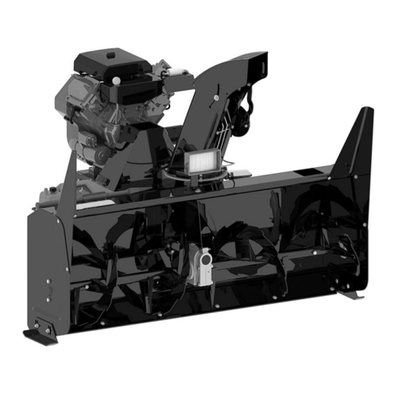
- Page 1 OWNER’S MANUAL Model Number 700360-9 Snowblower BERCO 54’’ PRESTIGE SNOWBLOWER ALL TERRAIN VEHICLES * ASSEMBLY * REPAIR PARTS * OPERATION * MAINTENANCE CAUTION: READ & FOLLOW ALL SAFETY RULES & INSTRUCTIONS BEFORE OPERATING YOUR EQUIPMENT *106250* 106250_EN M-01...
- Page 2 This warranty gives you specific legal rights. You may also have other rights, which vary from country to country. NOTE: Bercomac reserves the right to change or improve the design of any part or accessory without assuming any obligation to modify any product previously manufactured.
-
Page 3: Table Of Contents
TABLE OF CONTENTS PAGE INTRODUCTION ..............................SAFETY PRECAUTIONS ............................. SAFETY DECALS ..............................ASSEMBLY Conversion Table, Glossary, Tools Required ..................Vehicle Preparation ..........................Preparing the Subframe .......................... Installing on the Vehicle .......................... Engine Preparation ..........................Saddle Preparation ..........................OPERATION Operating the Snowblower ........................Electric Controls ............................ -
Page 4: Introduction
INTRODUCTION TO THE PURCHASER This new accessory was carefully designed to give years of dependable service. This manual has been provided to assist in the safe operation and servicing of your attachment. NOTE: All photographs and illustrations in the manual may not necessarily depict the actual models or attachment, but are intended for reference only and are based on the latest product information available at the time of publication. -
Page 5: Safety Precautions
SAFETY PRECAUTIONS Careful operation is your best insurance against an accident. Read this section carefully before operating the vehicle and accessory. This accessory is capable of amputating hands and feet and throwing objects. Failure to observe the following safety instructions could result in serious injury. All operators, no matter how experienced they may be, should read this and other manuals related to the vehicle and accessory before operating. - Page 6 SAFETY PRECAUTIONS OPERATION: MAINTENANCE AND STORAGE Do not put hands or feet near, under or inside rotating parts. When cleaning, repairing or inspecting the vehicle and accessory, make certain that all moving parts Exercise extreme caution when operating on or have stopped.
-
Page 7: Safety Decals
SAFETY DECALS REPLACE IF DECALS ARE DAMAGED SEE PARTS BREAKDOWN FOR DECAL LOCATION Symbol Description Decal #105126 To avoid serious injury: Keep hands, feet & clothing away from rotating auger while engine is running. Decal #105127 To avoid serious injury: Keep hands out of this discharge chute while engine is running. -
Page 8: Assembly
ASSEMBLY GLOSSARY CONVERSION TABLE Quad = V.T.T., A.T.V. 1’’ (po, in) 25.4 mm Véhicule tout terrain V.T.T. 1’ (pi, ft) 0.3 m All terrain vehicle A.T.V. 1 psi (lb/in 6.89 kPa P.T.O. = P.D.F 1 lb 0.45 kg Power take-off (P.T.O) 1 lbf 4.4 N... -
Page 9: Vehicle Preparation
ASSEMBLY VEHICLE PREPARATION ASTENING THE SUBFRAME Choose one of the three following options as a means of fastening the subframe. PTION Install the lift strap (item 1) by making a loop around the front suspension arm of the vehicle. Tighten the loop firmly. PTION Remove the nut and bolt from the vehicle’s front suspension arm. - Page 10 ASSEMBLY Among the three following configurations, choose the height of the hitch support. There must be a maximum of ground clearance. (Configuration A) does not have the hitch support plates (item 1). If applicable, assemble the hitch support plates on the hitch support (item 2) with four hex bolts 3/8"...
-
Page 11: Installing On The Vehicle
ASSEMBLY INSTALLING ON THE VEHICLE Place the hitch (item 1) on the tow hitch ball and secure in place with a pin (item 2) and a hair pin (item IMPORTANT Make sure the vehicle never comes into contact with the subframe even when the vehicle’s suspensions are compressed to the maximum. - Page 12 ASSEMBLY Install the snowblower hitch (item 1) on the wheel support (item 2) of the subframe with a pin (item 3) and hair pin 4mm (item 4). Assembling the snowblower to the subframe Secure the winch hook (item 1) in the lift eye on the hitch (item 2).
-
Page 13: Engine Preparation
ASSEMBLY ENGINE PREPARATION: CAUTION Oil must be added to this motor. Please refer motor’s owner’s manual instructions and proper winter oil recommendations. Connecting the wire assembly: The kit is equipped with a connector which will permit you to remove the snowblower quickly without having to remove the wiring. -
Page 14: Operation
OPERATION WARNING WARNING Read the vehicle's owner’s manual carefully. Be Never touch with your hands or feet the thoroughly familiar with the controls & proper snowblower’s fan, auger or the chute because use of the attachment. Know how to stop the this is the most frequent cause of accidents unit &... -
Page 15: Snowblowing Technique
OPERATION ADJUSTING THE PRESSURE OF THE SNOWBLOWING TECHNIQUE SUBFRAME TIRES ON THE GROUND When removing snow, do not use the snowblower as a dozer blade to push snow. Allow snowblower to When the ground is soft, the vehicle may lose some ingest snow at its own speed. -
Page 16: Maintenance
MAINTENANCE WARNING WARNING Before doing any snowblower maintenance, -Do not attempt to clear plugged chute, auger or assembling or dismounting: fan of snow while the snowblower's engine is Apply parking brakes of the vehicle. running. Stop the snowblower engine and remove the -Disengage snowblower. -
Page 17: Lubrication
MAINTENANCE LUBRICATION A U G E R A N D S H E A R B O L T REPLACEMENT SUBFRAME WHEELS Grease the wheel axles, the fork pivots after every sixteen hours of use. The shear bolts are to be considered a IMPORTANT: Apply oil at all pivot points. -
Page 18: Belt Replacement
MAINTENANCE CAUTION BELT TENSION ADJUSTMENT If the spring becomes too stretched, it is possible to Never use the snowblower without the belt guard. the change the position of the spring on the tensioner. Just move the carriage bolt (item 1), the sleeve (item 2) the flat washer (item 3) and nut (item 4) to position BELT REPLACEMENT B instead of position A. -
Page 19: Replacing The Augers, Fan And The Gear Box
MAINTENANCE 6. Loosen the two set screws (item 1) from ball REPLACING THE AUGERS, FAN AND / bearing behind the snowblower (it may be OR THE GEAR BOX necessary to heat the set screw and the center of the bearing around the shaft to soften the Loctite). To identify the part numbers, refer to the snowblower parts breakdown. -
Page 20: Dismounting & Storage
DISMOUNTING AND STORAGE DISMOUNTING STORAGE 1. Select a level surface, set the parking brake, stop 1. Clean the snowblower and subframe thoroughly. the engine and remove the ignition key to prevent 2. Paint all the parts wear the paint has worn out. accidental starting. -
Page 21: Troubleshooting
TROUBLESHOOTING * Please refer to parts breakdown section for parts identification. PROBLEM POSSIBLE CAUSES CORRECTIVE ACTION Snowblower vibrates or is Damaged pulley Replace pulley abnormally noisy or bouncing. Damaged bearing Replace the bearing Fan or the augers are damaged Remove and straighten or replace the parts Fan or auger bushings are worn Replace with new bushings... - Page 22 TROUBLESHOOTING * Please refer to parts breakdown section for parts identification. PROBLEM POSSIBLE CAUSES CORRECTIVE ACTION Chute plugs easily. Snowblower engine running too Run engine at full R.P.M. during slowly. snow blowing operation. Advancing too quickly with vehicle. Reduce vehicle’s speed.. Allow snowblower to ingest snow at its own speed.
-
Page 23: Torque Specification Table
TORQUE SPECIFICATION TABLE GENERAL TORQUE SPECIFICATION TABLE USE THE FOLLOWING TORQUES WHEN SPECIAL TORQUES ARE NOT GIVEN NOTE: These values apply to fasteners as received from supplier, dry or when lubricated with normal oil. They do not apply if special graphited or moly disulphide greases or other extreme pressure lubricants are used. This applies to both UNF and UNC threads. -
Page 24: Rotation System With Chute
PARTS BREAKDOWN ROTATION SYSTEM WITH CHUTE... - Page 25 PARTS LIST ROTATION SYSTEM WITH CHUTE Ref. Qty. Part # English description Description française Réf. Qté. Pièce # Chute Goulotte 106172 Bracket Support 103971 Reinforcement plate Plaque de renforcement 103972 Spacer Espaceur 103368 Rotation ring Anneau de rotation 103974 Spacer Espaceur 103361 Bracket...
-
Page 26: Saddle Assembly
PARTS BREAKDOWN SADDLE ASSEMBLY... - Page 27 PARTS LIST SADDLE ASSEMBLY Ref. Qty. Part # English description Description française Réf. Qté. Pièce # Seat cover Couvre-siège 103987 Control board Tableau de contrôle 104011 Switch support Support de commutateur 104012 Safety switch ass'y Commutateur de sécurité ass'é 104014 Ignition switch Commutateur d'ignition 104015...
-
Page 28: Subframe
PARTS BREAKDOWN SUBFRAME... - Page 29 PARTS LIST SUBFRAME Ref. Qty. Part # English description Description française Réf. Qté. Pièce # Subframe Sous-châssis 104957 Wheel support Support de roue 104770 Rear bracket Fixation arrière 104956 Hitch support Support d'attache 104958 Adjustment tube Tube d'ajustement 104959 Hitch Attache 104639 Hitch Ball Support...
-
Page 30: Snowblower
PARTS BREAKDOWN SNOWBLOWER... - Page 31 PARTS LIST SNOWBLOWER Ref. Qty. Part # English description Description française Réf. Qté. Pièce # Frame 54" Châssis 54" 106161 Hitch Attache 106162 Bender Tendeur 106163 Guard Garde 106164 Belt guard Garde-courroie 106166 V-belt, BX-55 Courroie en V, BX-55 106110 Engine support Support moteur 106168...
- Page 32 PARTS LIST SNOWBLOWER Ref. Qty. Part # English description Description française Réf. Qté. Pièce # Chute shovel Pelle à goulotte 105700 Goupille 105365 Hair pin 2mm Goupille à ressort 2mm 102430 Spacer Espaceur 103361 Pulley Poulie 106138 Goupille 103070 Skid shoe Patin 103188 Hair pin 3mm...
- Page 33 PARTS LIST SNOWBLOWER Ref. Qty. Part # English description Description française Réf. Qté. Pièce # Hex. bolt 3/8" n.c. x 1 3/4" GR5 Boulon hex. 3/8" n.c. x 1 3/4" GR5 Hex. bolt 3/8" n.c. x 2 3/4" GR5 Boulon hex. 3/8" n.c. x 2 3/4" GR5 Hex.
-
Page 34: Options
OPTIONS EXTENSION AND SIDE WIDENING ANGLE KIT #700461 . EXTENSION PANEL SUBFRAME EXTENSION Widens the snowblower by #700473 6’’ (15cm) Adds about 10’’ (25cm) to the height #700485 and adds about 7’’ (18cm) to the of the snowblower For bigger vehicles height. - Page 35 NOTES...
- Page 36 WHEN PERFORMANCE & DEPENDABILITY ARE NON NEGOTIABLE ! Ber comac Limitée 92, For t in Nor t h, Adstock, Quebec, Canada, G0N 1S0 WWW.BERCOMAC.COM PRINTED IN CANADA (ORIGINAL NOTICE)
Need help?
Do you have a question about the 700360-9 and is the answer not in the manual?
Questions and answers