Table of Contents
Advertisement
Advertisement
Table of Contents

Related Manuals for SoundCraft DC 2020


Summary of Contents for SoundCraft DC 2020
- Page 1 SOUNDCRAFT USER GUIDE...
- Page 2 Information in this manual is subject to change without notice and does not represent a commitment on the part of the vendor. Soundcraft Electronics Ltd. shall not be liable for any loss or damage whatsoever arising from the use of information or any error contained in this manual, or through any mis-operation or fault in hardware or software contained in the product.
-
Page 3: Table Of Contents
Table of Contents Introduction Introduction Typical-Use Environment Warranty Installation Dimensions Assembling The Console Stand Precautions and Safety Instructions Installation Connections Connecting the DC2020 to a MAC or to a PC Installing the MAC or PC Emulation Software 2.10 Patchbay EDAC Pin Identification Chart and Pinouts 2.11 Block Diagrams... - Page 4 Control-room Phones and Speakers 4.35 Control-room Phones and Speakers 4.36 Patchbay 4.39 Patchbay Fascia 4.40 Patchbay Wiring 4.41 Automation Guide 4.47 Introduction 4.49 Introduction to the Automation 4.50 Project Management 4.55 Introduction 4.56 The Automation Pages 4.61 The Automation Pages 4.62 Alphanumeric Keypad 4.64...
- Page 5 Stereo Inputs Safe 4.97 Stop Edit Options 4.98 Studio 4.99 Studio Configuration 4.100 Studio Utilities 4.101 Switch Select On Tape Stop 4.102 Tape Machine Selection 4.103 Timecode Generator 4.104 Title Configuration 4.105 Title Utilities 4.107 Track List 4.108 User 4.109 User Configuration 4.110 User Utilities...
- Page 6 DC2020...
-
Page 7: Introduction
Introduction DC2020 Introduction... -
Page 8: Introduction
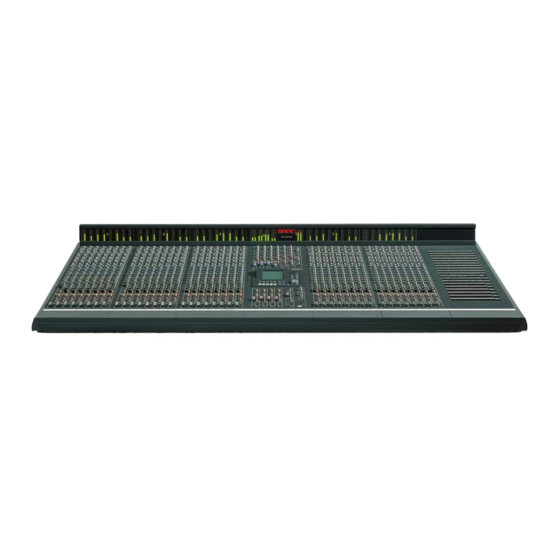
Introduction Overview The DC2020 is an in-line studio mixing console. It is available in three sizes; 24, 32 and 40 input channels. Each of these is available with a patchbay. The console features the following: Mix Automation, which controls: 4 switches and 1 fader per input channel (Aux1 ON, Aux3 ON, Channel CUT, Monitor CUT and the Monitor Fader);... -
Page 9: Typical-Use Environment
Typical-Use Environment The console is designed to be used with a multi-track tape machine or any LTC/MIDI Timecode generating device. Timecode is read by the console to provide the time base for the Mix Automation. Software The program which runs the automation system within the console is held on the hard-disk drive. -
Page 10: Warranty
Equipment has been properly installed in accordance with instructions con- tained in Soundcraft’s manual; and b) the End User has notified Soundcraft or the Dealer within 14 days of the de- fect appearing; and c) no persons other than authorised representatives of Soundcraft or the Dealer have effected any replacement of parts maintenance adjustments or repairs to the Equipment;... -
Page 11: Installation
Installation DC2020 Installation... -
Page 12: Dimensions
Dimensions 728.00mm 171.87mm 28.66" 6.77" CONSOLE WIDTH WEIGHT 24 ch 1368.40mm 53.87" 72kgs 158lbs 24ch + Patchbay 1688.00mm 66.46" 80kgs 176lbs 32ch 1688.00mm 66.46" 80kgs 176lbs 32ch + Patchbay 2007.60mm 79.04" 88kgs 194lbs 40ch 2007.60mm 79.04" 88kgs 194lbs 91.62" 40ch + Patchbay 2327.20mm 96kgs 212lbs... -
Page 13: Assembling The Console Stand
Assembling The Console Stand DC2020 Installation... -
Page 14: Precautions And Safety Instructions
Precautions and Safety Instructions General Precautions Avoid storing or using the mixing console in conditions of excessive heat or cold, or in positions where it is likely to be subject to vibration, dust or moisture. Do not use any liquids to clean the fascia of the unit: a soft dry brush is ideal. Use only water or ethyl alcohol to clean the trim and scribble strips. - Page 15 Caution! DO NOT use unbalanced microphones or battery powered condenser microphones without isolating the +48V phantom power: degraded performance or damage to the microphone may result. The sensitivity of the XLR inputs is variable from -2dBu to -70dBu and +10dBu to -20dBu in two ranges (for +4dBu at the Mix outputs).
-
Page 16: Installation
Installation The DC2020 is designed for reliability and high performance, and is built to the highest standards. Whilst great care has been taken to ensure that installations are made as troublefree as possible, care taken at this stage, followed by correct setting up will be rewarded by a long life and reliable operation. -
Page 17: Connections
Connections Wiring conventions The DC2020 uses two different types of audio connector: 3-pin XLR and " 3-pole jacks. The latter are used in several configurations, as shown below (note that the patchbay versions have no 1/4" jack sockets except for the SMPTE In and Out connections). -
Page 18: Bnc Connector
DIN Connectors The MIDI IN signal is buffered by an opto-isolator. MIDI THRU MIDI OUT D-Type Connectors Ports 1, 2 and 4 are not used. Port 3 conforms to EIA RS-422A. It is used to connect to Sony 9-pin connectors, see Appendix A for details. -
Page 19: Connecting The Dc2020 To A Mac Or To A Pc
Connecting the DC2020 to a MAC or to a PC You may connect the DC2020 to either a MAC or a PC to provide touch-screen emulation. In either case you will need to make or obtain a suitable connecting lead. The connections required are shown in the diagrams below. -
Page 20: Installing The Mac Or Pc Emulation Software
Installing the MAC or PC Emulation Software Software is provided with the DC2020 which allows the touch screen of the console to be used via a computer interface. Such software is available for either the PC or the Macintosh. The software is an emulation of the touch screen but allows use of a mouse (or other pointing device) and input from the computer keyboard. -
Page 21: Patchbay Edac Pin Identification Chart And Pinouts
Patchbay EDAC Pin Identification Chart and Pinouts DC2020 Installation 2.11... - Page 22 TAPE TRACKS 1-8 A ....TRET+6 h ....GND B .
- Page 23 TAPE TRACKS 9-16 A ....TRET+14 h ....GND B .
- Page 24 TAPE TRACKS 17-24 A ....TRET+22 h ....GND B .
- Page 25 TAPE TRACKS 25-32 A ....TRET+30 h ....GND B .
- Page 26 TAPE TRACKS 33-40 A ....TRET+38 h ....GND B .
- Page 27 AUX & FOLDBACK O/P, STEREO I/P, STUDIO PHONES A ....STL+3 h ....GND B .
- Page 28 CONTROL-ROOM O/P, MIX O/P, 2TRACK I/P, STUDIO SPEAKERS, ALT SPEAKERS A ....2TBSL+ h ....GND B .
-
Page 29: Line Inputs
LINE INPUTS 1-24 A ..LINE1+ AK ..LINE17- BU ..GND B ..LINE1- AL . -
Page 30: Tie Lines
TIE LINES 1-24 A ..T-LINE1+ AK ..T-LINE17- BU ..GND B ..T-LINE1- AL . - Page 31 TIE LINES 25-48 A ..T-LINE25+ AK ..T-LINE41- BU ..GND B ..T-LINE25- AL .
- Page 32 TIE LINES 49-72 A ..T-LINE49+ AK ..T-LINE65- BU ..GND B ..T-LINE49- AL .
- Page 33 TIE LINES 73-96 A ..T-LINE73+ AK ..T-LINE89- BU ..GND B ..T-LINE73- AL .
- Page 34 TIE LINES 97-120 A ..T-LINE97+ AK ..T-LINE113- BU ..GND B ..T-LINE97- AL .
-
Page 35: Block Diagrams
Block Diagrams DC2020 Block Diagrams... - Page 36 Mono Input DC2020 Block Diagrams...
- Page 37 Stereo Input/Groups DC2020 Block Diagrams...
- Page 38 Aux Master DC2020 Block Diagrams...
- Page 39 Studio, Foldback and Oscillator/Talkback DC2020 Block Diagrams...
- Page 40 Mix and Control Room Monitor DC2020 Block Diagrams...
-
Page 41: Functional Descriptions
Functional Descriptions DC2020 Functional Descriptions... - Page 42 DC2020 Functional Descriptions...
-
Page 43: Mono Inputs
Mono Inputs DC2020 Mono Inputs... -
Page 44: Mono Input
Mono Input Input Control Section If the +48V switch is depressed then +48V phantom power is supplied to the rear-panel Mic XLR socket When the LINE switch is released the input to the channel is via the Mic XLR socket; when the LINE switch is depressed the input is via the 1/4"Line socket The input sensitivity is -40dBu to +10dBu for Line input and -60dBu to -10 dBu for Mic input. - Page 45 Note: Channels 25-40 may not be present on your console. The EQ is split into two parts. The first part is the HF/LF EQ, this consists of two equalisers which may be independently configured as shelving or bell-response filters. The HF Bell/Shelf switch configures the HF EQ. The bell-response Q factor is 1.5 .
- Page 46 Note: the Insert Point (via rearcon panel, or patchbay if fitted) is placed after the HF/LF EQ and is switched, with this EQ section, between the Channel path and the Monitor path, via the HF/LF EQ’s EQ TO MON switch. Auxiliary Controls The AUX1 Level control is permanently connected to the Monitor path and is post the Monitor Cut and the Monitor Fader.
-
Page 47: Pan Control
When the POST switch is depressed, both the FB1 and FB2 paths are fed post-fade; when the POST switch is released the signals are pre-fade. Pan Control The MON PAN control positions the Monitor signal within the stereo image carried by the MONL and MONR buses. These buses connect with the Mix Left & Right board where they are summed with signals carried by the MIXL and MIXR buses, and also summed with Talkback signals (see the Stereo Master chapter for more details). -
Page 48: Automated Fader And Switch Modes
The Channel CUT switch is a soft switch, i.e. this switch provides an input to the Automation. The Automation , in turn, controls the Cut circuit and also the Channel CUT and Arm LEDs The REC LED indicates when the tape machine is in record mode for the track which is connected to this channel. - Page 49 Write. If the Fader is moved or a Switch is pressed this is written into the Mix Data, creating a new Mix, or writing over any previous Mix data. The mode of a Fader or Switch is changed by pressing the appropriate mode switch, labelled SW for Switches and FDR for the Fader.
- Page 50 Rear Connector Panel Microphone Input - Female XLR Pin 1 Screen Pin 2 Hot (in phase signal) Pin 3 Cold (out of phase signal The Patchbay version does not have the following connectors on the Input Rear Connector Panel: see the Patchbay section of this chapter, and the EDAC connector pin lists in chapter2, for details.
-
Page 51: Group/Stereo Input
Group/Stereo Input DC2020 Group/Stereo Input 4.11... -
Page 52: Group/Stereo Input
Group/Stereo Input Stereo Input The -10 switch changes the nominal input level from +4dBu, when the switch is released, to -10dBV, when the switch is depressed. The stereo 2-band shelving EQ has a +/-15dB cut and boost at 3kHz, which is controlled by the HF control, and a +/-15dB cut and boost at 150Hz, which is controlled by the LF control. - Page 53 bouncing. Only one of the pair of signals is considered here. The summed Group signal is passed through an unbalanced Insert point on the rear connector panel. The Insert-point Return signal is fed to the Fader, which provides a gain of +10dB at the top of its travel.
- Page 54 Rear Connector Panel Stereo Input (Non-Patchbay Only) The stereo inputs are electronically balanced. The left input is normalled to the right input on the rear panel Jack sockets: if only a mono signal is available it is automatically routed to both Left and Right signal paths. Plugging a Jack plug into the Right socket disconnects the normalling.
-
Page 55: Auxiliary Master
Auxiliary Master DC2020 Auxiliary Master 4.15... -
Page 56: Auxiliary Master
Auxiliary Master There are four auxiliary buses. Each Input Module is able to put signals on each of the four Aux buses. Aux1 & Aux2 are only fed from the Monitor path, post-fade. Aux3 & Aux4 may be fed from The Channel path or the Monitor path, both post-fade. - Page 57 The CUT switch is a soft switch, i.e. this switch provides an input to the Automation. The Automation , in turn, controls the electronic Cut circuit, which is post-pot. The Automation also controls the adjacent CUT and Arm LEDS ( red and amber respectively).
- Page 58 4.18 DC2020 Auxiliary Master...
-
Page 59: Studio Outputs & Fb Masters
Studio Outputs & FB Masters DC2020 Studio Outputs & FB Masters 4.19... -
Page 60: Studio Outputs & Foldback Masters
Studio Outputs & Foldback Masters Studio Outputs The signal level available at the Studio Speakers Output jacks on the rearcon panel is controlled by the C/RM TO STUDIO SPKRS pot. The input to this control is taken from the source selector switches on the Control-room Speakers/Phones Panel. - Page 61 from each Input Module: they are both switched (together) by the POST switch on each Input Module. Signals from Stereo Input Modules When the STEREO switch is released, Mono signals (L+R) from the Stereo Input channels are connected to both the FB1 and the FB2 channels. The level of the signal from each of the Stereo Inputs is controlled by the FB1/L and FB2/R level controls on each of the Stereo Inputs.
-
Page 62: Rear Connector Panel
Rear Connector Panel The Studio and Foldback outputs are ground compensated. This provides a very (Non-Patchbay Only) effective way of optimising noise immunity, without the complexity of balanced outputs. Ground compensated outputs cancel the effects of variation in ground potential between the mixer and other equipment which would otherwise show up as hum. -
Page 63: Oscillator & Talkback Panel
Oscillator & Talkback Panel DC2020 Oscillator & Talkback Panel 4.23... -
Page 64: Oscillator And Talkback Panel
Oscillator and Talkback Panel Power Indicators There are four LEDs which indicate the presence of power on power rails within the machine. They are 48V, 17V, 12V and 5V Oscillator The Oscillator is used to set signal levels at the tape machine. This oscillator isn’t to be confused with the Slate Oscillator which is used for marking the tape. - Page 65 When the Talkback to STUDIO PHONES switch is pressed the signals to the Studio Phones are attenuated by 20dB (nominal) and the talkback signal from the in-built mic is added to the attenuated signal. The Control-room phones/speakers signals are also attenuated by a nominal 20dB when the STUDIO PHONES switch is pressed.
- Page 66 4.26 DC2020 Oscillator & Talkback Panel...
-
Page 67: Control Groups
Control Groups DC2020 Control Groups 4.27... -
Page 68: Control Groups
Control Groups There are four Control Groups. Each Mono Input strip may be assigned to one of the Control Groups at a time, or assigned to none of them. Channel Pressing the SOLO switch will put all of the Channels of the Mono Inputs which are assigned to this particular Control Group into Solo mode: the solo mode will be either Solo or Solo-in-place, depending upon the status of the SIP switch on the Stereo Master panel. - Page 69 Switch and Fader Modes The mode of the Switches or Faders on all of the assigned Mono Inputs is changed by pressing the appropriate mode switch, labelled SW for Switches and FDR for the Fader. Pressing the Mode switch causes the mode to be cycled through in the following sequence: Manual, Read, Armed and Write.
- Page 70 4.30 DC2020 Control Groups...
-
Page 71: Stereo Master
Stereo Master DC2020 Stereo Master 4.31... -
Page 72: Stereo Master
Stereo Master All of the controls on the Stereo Master panel interface directly with the Automation. The Solo System The Channel and Monitor paths on each Input Module have SOLO switches. Normally, if a SOLO switch is pressed, the signal it represents is routed to the PFL/AFL system and the Control-room output is switched to listen to the Soloed signal. - Page 73 Press and hold the SEL switch on the Stereo Master panel, then press whichever Cut switches on the panels listed above which you wish to select. The amber LED associated with each selected CUT switch will illuminate to indicate that the switch is selected.
- Page 74 Rear Connector Panel Mix Out Left - 3-pole Jack (Non-Patchbay Only) Hot (in phase signal) Ring Cold (out of phase signal) Sleeve Ground Mix Out Right - 3-pole Jack Hot (in phase signal) Ring Cold (out of phase signal) Sleeve Ground Mix Insert Left- 3-pole Jack Return...
-
Page 75: Control-Room Phones And Speakers
Control-room Phones and Speakers DC2020 Control-room Phones and Speakers 4.35... -
Page 76: Control-Room Phones And Speakers
Control-room Phones and Speakers The stereo Control-room signals are sourced from either one of two 2-track inputs from Jacks on the rear connector panel, or from the main mix. The sources can be mixed by pressing more than one source switch. In addition the Control-room signals can be sourced from the Solo/PFL/AFL system. - Page 77 Input Rear Connector Panel (Non-Patchbay Only) 2-Track A Left and Right Inputs - 3-pole Jacks Hot (in phase signal) Ring Cold (out of phase signal) Sleeve Ground 2-Track B Left and Right Inputs - 3-pole Jacks Hot (in phase signal) Ring Cold (out of phase signal) Sleeve...
- Page 78 4.38 DC2020 Control-room Phones and Speakers...
-
Page 79: Patchbay
Patchbay DC2020 Patchbay 4.39... -
Page 80: Patchbay Fascia
Patchbay Fascia pbface.eps 4.40 DC2020 Patchbay... -
Page 81: Patchbay Wiring
Patchbay Wiring The DC2020 Patchbay is an 8-module wide panel which provides patching for up to 40 inputs, master functions and a maximum of 120 tie lines. The following simplified diagrams show how the Bantam-type sockets are wired. The complete list of EDAC plug connections is given in Chapter 2. The diagram on the right shows the Bantam-Type Socket convention used in drawing the... -
Page 82: Input Channel
Line Inputs 25-40 Input Channel 25-40 Note: Line Inputs 25 to 40 appear on their associated LINE IN input patchcard only, they do not have a normalling patchcard. To Line Input n INS SND INS RET From Insert Send Amp. To Insert Return Amp. -
Page 83: Group Outputs
Group Inserts Group Inserts From Group Send Amp. To Group Return Amp. Group Outputs Group Outputs GROUP OUTPUT From Group Output n SMPTE Timecode SMPTE Timecode SMPTE OUT SMPTE OUT on back of on patchbay console From SMPTE Sender SMPTE IN SMPTE IN on back of on patchbay... -
Page 84: Stereo Inputs
Stereo Inputs STEREO INPUTS L or R STE IN on EDAC To Stereo Input on Console Aux Outputs Aux Outputs AUX OUTPUT AUX OUTPUT ON EDAC Aux Output From Console. Foldback Outputs Foldback Outputs FOLDBACK O/Ps F/B OUTPUT ON EDAC Foldback Output From Console. - Page 85 Studio Phones Studio Phones Outputs STUDIO PHONES L or R STUDIO PHONES OUTPUT ON EDAC Studio Phones Output From Console. Studio Speakers Studio Speakers Outputs STUDIO SPEAKERS L or R STUDIO SPEAKERS OUTPUT ON EDAC Studio Speakers Output From Console. Mix Inserts &...
-
Page 86: Track Returns
2-Track Returns 2-Track Returns 2-TRK A or B L or R 2-TRK Inputs To 2-Trk Input on EDAC in Console Control-room & Alternative Speaker Outputs Control-Room and Alternative Speaker Outputs C/ROOM OUTPUT L or R CRM OUTPUT ON EDAC C/room Output From Console. -
Page 87: Automation Guide
Automation Guide DC2020 Automation Guide 4.47... - Page 88 4.48 DC2020 Automation Guide...
-
Page 89: Introduction
Introduction DC2020 Introduction 4.49... -
Page 90: Introduction To The Automation
Introduction to the Automation Control Panel The Central Control Panel is the user interface for the Automation System. The Automation Control Panel appears as follows: Screen The Screen is a touch-sensitive LCD unit. There are 60 touch-sensitive areas on the display: 10 columns by 6 rows. - Page 91 Keyboard There are 22 buttons, some with illumination, which are for the functions most commonly used during mixing; there is also a Jog Wheel which is used for selecting pages and timecodes. The Jog Wheel may also be used to control the Tape Machine, providing that the Tape Machine will support this function.
- Page 92 Note: pre-roll and post-roll times may be set up for the Locate points and the Drop In and Drop Out points. RECORD ENABLE is selected by pressing the RECORD ENABLE button: a LED above the switch glows to indicate selection. It is deselected by pressing the RECORD ENABLE button again.
- Page 93 The GLIDEBACK button switches GLIDEBACK mode on and off: an adjacent LED indicates its status. Glideback determines how motorised faders react when they are in Armed mode, and when they change from Write to Read Mode. The MODE SNAP button may be used at any time to store a snapshot of the modes of all of the Automated functions.
- Page 94 4.54 DC2020 Introduction...
-
Page 95: Project Management
Project Management DC2020 Project Management 4.55... -
Page 96: Introduction
Introduction The DC2020 features a project management system, designed to provide easy storage and retrieval of mix data. The system means that the console can be used by a large number of different engineers, each working on their own projects, and enables each engineer to store mixes for his/her various projects in a directory system, where they can be easily located and recalled in the future. - Page 97 Press the ’Studio Config’ touch-pad on the screen. This brings up the ’Studio Config’ page, which allows you to set up or change the following: "The name of the studio (set to ’Soundcraft’ at the factory) "The type of tape machine being used (set to Midi Timecode Master at the factory) "The local date and time.
- Page 98 To change any of these, simply touch the relevant part of the screen, which will bring up either the QWERTY keyboard, list of supported machines, or numerical keypad respectively. Other information displayed on this page includes the percentage amount of free hard disk space available, the software version number being run, and the number of channels in the console.
- Page 99 recall it, delete unwanted mixes or ’protect’ valuable mixes to guard against accidental deletion. You can also name each individual mix if required, although the system gives each mix a default number as they are created, so naming is not essential.
- Page 100 4.60 DC2020 Project Management...
-
Page 101: The Automation Pages
The Automation Pages DC2020 The Automation Pages 4.61... -
Page 102: The Automation Pages
The Automation Pages The Pages which appear on the Automation System’s screen belong to either the Main Automation System or to the Setup System. There is one page which is in neither of these systems: the Group Assignments page is accessed directly from the Group Assign button on the Automation Panel. - Page 103 number of Titles. The Title directory is the bottom level of the directory structure: individual mix passes are stored as files in the Title directory. Configuration data is stored on disk. This data is stored at an appropriate level in the directory structure.
-
Page 104: Alphanumeric Keypad
Alphanumeric Keypad The Alphanumeric Keypad appears as follows: Text to be edited is here. <- & ’ " SPACE shift Cancel The functionality of this page is probably self-evident. However it will be helpful if the following features are brought to your attention: Edit Line The text to be entered/edited is displayed at the top of the screen. -
Page 105: Channel List
Channel List The Channel List page appears as follows: Channel List 1 Vocal 1 2 Vocal 2 3 Strings L Copy to Blank Insert Delete Tracks Channel Edit Print Cancel The following information is presented: Screen Title Area Title only. Scrollable Data The list of Channels together with a description of each input is displayed. -
Page 106: Channel Solo-In-Place Safe
Channel Solo-In-Place Safe The Channel Solo-in-Place Safe page appears as follows: Channel SIP Safe Clear Monitor Stereo all safe all safe SIP Safe Inputs This page allows you to set and clear the SIP safe status of individual Channels. Channels which are set to safe are shown in reverse text. Set all safe. -
Page 107: Default Mode On Stop
Default Mode On Stop The Modes page appears as follows: Touch-pads Default Mode on stop These Touch-pads allow you to define the modes which the switches and faders will go into when the Tape Machine stops. The options are: ARMED, WRITE, MANUAL and READ. -
Page 108: Default Settings
Default Settings The Default Settings page appears as follows: Default Settings Frame Rate Change Fader 4095 Gain Gain The Frame Rate is the default setting for a newly-created Title. The value in the touch-pad may be cycled through by repeated pressing. Fine Tuning Of Moving Faders It is possible to fine-tine the motion of the faders to optimise the fader movements for either quiet operation or for the fastest response, depending on the demands of... -
Page 109: Edit Midi Events
Edit Midi Events The appearance of the Edit Midi Events page changes according to the Event Type. The blank Event screen appears as follows. Edit Midi Event Event Type TEST Cancel Note: Extra fields appear according to the Event type selected. To change the event type, press the Event type field. -
Page 110: Glideback
Glideback The Glideback page appears as follows: Glideback 1-8 Channel 1 frame Master dB 1 per Frame 10 Master to all 9-16 17-24 25-32 33-40 Touch-pads The Glide rate is expressed in dB per frame. The default setting is 1dB per 10 frames. -
Page 111: Group Assignments
Group Assignments The Group Assignments page is accessed by pressing the Group Assign button on the Automation panel. It appears as follows: Group Assignments Select Select Select Select Group 1 Group 2 Group 3 Group 4 Clear Clear Clear Clear Group 1 Group 2 Group 3... -
Page 112: Meterbridge Set-Up
Meterbridge Set-up The Meterbridge Set-up page appears as follows: Meter Bridge Setup 9-16 17-24 25-32 33-40 Return Return Return Return Send Stereo Control Groups Inputs Room Brightness Peak Hold Touch-pads The meters for the input channels are switched, in groups of eight, between following the tape send or tape return signals. -
Page 113: Midi Events
Midi Events The Midi Events page appears as follows: Midi Events Title: Project: User: Prog Ch1 17 01:03:54:17 Edit Copy from Playback Event Cue List Event Delete Edit Edit Display Event Name Timecode Names The following information is presented: Screen Title Area The page title Subsidiary Data Area The Title, the Project and the User. - Page 114 where X is the next available number. Note that the numbers are not in timecode order: they are in the order that the Midi Events were inserted into the list. Edit Timecode. This allows you to edit the timecode value of the Midi Event which is displayed in the Cursor Line.
-
Page 115: Mix
The Mix page appears as follows: Mix: New Mix Pass Title: Song 1 Percentage free: 95% Project: PROJECT 0001 User: DC2000 User 0001 Program start 01:09:55:00 Used Cue Point 01:09:57:00 Used Cue Point 01:09:58:00 Title Project Config List Edit Edit Delete Title Cue Name... - Page 116 Edit Timecode. This presents a small numeric keypad on the screen. This allows you to enter new time information into the Cue which is on the Cursor Line. You may also use the Jog Wheel to change the time information frame-by-frame. Delete Cue.
-
Page 117: Mix Information
Mix Information The Mix Information page appears as follows: The following information is presented: Screen Title Area Title only. Scrollable Data The following fields are available within the scrollable area. Each of them may be positioned within the Cursor Line, and selected by touching the Cursor Line. The data which you enter here is stored for information only: it has no meaning to the Automation system. - Page 118 Touch-pads Print Info. This prints the Mix Information to the parallel port. Track List. This takes you to the Track List page. Channel List. This takes you to the Channel List page. OK. This returns you to the Mix List page. 4.78 DC2020 The Automation Pages...
-
Page 119: Mix List
Mix List The Mix List page appears as follows: Mix List Title: Title0001 Project: PROJECT 0001 User: DC2000 User 0001 New Mix Pass Display Date/Size Page Info Edit Protect Delete Title Utilities The following information is presented: Screen Title Area The Title name. - Page 120 Delete Mix. This deletes the Mix in the Cursor Line. Title Utilities. Pressing this takes you to the Title Utilities page. 4.80 DC2020 The Automation Pages...
-
Page 121: Monitor Solo-In-Place Safe
Monitor Solo-In-Place Safe The Monitor Solo-In-Place Safe page appears as follows: Monitor SIP Safe Clear Channel Stereo all safe all safe SIP Safe Inputs This page allows you to set and clear the SIP safe status of individual Monitors. Monitors which are set to safe are shown in reverse text. Touch-pads Individual, Numbered pads. -
Page 122: On Line Mix Edit Options
On-Line Mix Edit Options The On-Line Mix Edit Options page is selected via the Titles Utilities page. It appears as follows: On Line Mix Edit Options Edit mode The Edit Mode touch-pad toggles between On and Off. When it is set to ’On’ the shuttle wheel may be used to run the tape transport(s) forwards and backwards. -
Page 123: Presets
Presets Warning! It is important to state that presets cannot be added to a title which already contains cues or mixes. Important Note! It is not possible to access the Presets page when MIX ON is selected. Should you press SETUP when MIX ON is selected, the SETUP menu has a cross displayed over the touch pad labelled Presets to indicate that the Presets facility is unavailable at the present time. - Page 124 It is intended that these timed presets could be used to create an initial mix (using the "Create Mix" option on the Preset Utilities page). For instance, someone working with film/video could set up a preset to co-incide with the start of each scene.
- Page 125 Touch Pads: Preset Utilities. This takes you to the preset utilities page. Create Mix: This creates a new mix based on the list of timed presets which has been created. Timecode sort: This arranges the list of presets on the presets page in the timecode order.
- Page 126 Overwrite Preset: This will enable you to overwrite the settings associated with the current preset (i.e. The preset on the cursor line) with the current desk settings. This is a potentially dangerous operation so the user is asked to confirm that the operation should in fact go ahead.
- Page 127 Edit Timecode: This can be used to edit the timecode value associated with each preset. Upon pressing the pad a numeric keypad will appear. The user can then enter a timecode value and/or edit a timecode value using the jog wheel. Pressing the jog wheel tabs between Hours <...
- Page 128 Insert Preset: This enables you to insert a new preset above the preset on the cursor line. At this point it might be useful to mention the numbering scheme used to identify Presets. The scheme has three levels Top Level Preset (e.g 1 , 3 , 17 , 531 ) 2nd Level Preset (e.g 1.1 , 1.2 , 10.3 , 70.7 ) 3rd Level Preset (e.g.
-
Page 129: Project
Project The Project page appears as follows: Project: PROJECT 0001 User: DC2000 User 0001 Song 1 Tune 2 Project Protect User Config Page Title Project Edit Delete Utilities Title Title Title The following information is presented: Screen Title Area Project Name Subsidiary Data Area User Name. - Page 130 New Title. This creates a new entry at the bottom of the Title list. It will be in the form, ’Title 0001’. The actual number will be the next available one in sequence. Delete Title. This deletes the Title in the Cursor Line. Project Utilities.
-
Page 131: Project Configuration
Project Configuration The Project Configuration page appears as follows: Project config Memo <Blank> <Blank> Elapsed Time 0:11:18:25 The following information is presented: Screen Title Area The page title only. Memo Fields There are two fields which may be used for notes. Each field may contain up to 30 characters. -
Page 132: Project Utilities
Project Utilities The Project Utilities menu appears as follows: Project Utilities Backup Restore Duplicate Project Project Project Format Copy Change Floppy Floppy Mix disk Disable Shutdown Recalibrate Screen Console Console Touch Pads Backup Project. This will backup the data, which relates to the Project, on the hard disk to floppy disks. -
Page 133: Record Enable
Record Enable The Record Enable page appears as follows: Record Enable Enable Disable This page allows you to enable and disable the Record status of individual Channels. The REC LEDs (on the input strips) pulse whenever their respective Channel is record enabled. -
Page 134: Record Track Remap
Record Track Remap The Record Track Remap page appears as follows: Record Track Remap Reset Cancel mappings This facility allows you to use any track on a tape machine with any input channel on the console, and still retain control of the correct track when using drop-in and drop-out. -
Page 135: Remap Console
Remap Console The Remap Console page appears as follows: Remap Console Reset Cancel mappings This facility allows you to swap the stored mix movements for one input with that of another input. This would be useful if, for example, an input strip failed during a Mix session. -
Page 136: Set-Up
Set-up The Set-up menu is accessed by pressing the Set-up button on the Automation Control Panel. When the Menu is active the Set-up LED, which is next to the Set-up button, will be on. The Setup Menu allows access to pages which, in turn, allow you to set-up the console as required. -
Page 137: Stereo Inputs Safe
Stereo Inputs Safe The Stereo Inputs Safe page appears as follows: Stereo Inputs Safe Stereo SIP safe Clear Channel Monitor SIP Safe SIP Safe This page allows you to set and clear the SIP safe status of the Stereo Inputs. Touch-pads A, B, C, D. -
Page 138: Stop Edit Options
Stop Edit Options The Stop Edit Options page appears as follows: Stop Edit Options Write Faders to end of Mix Write Switches to end of Mix Update Faders to end of Mix Touch-pads Each of the Touch-pads toggles between ON and OFF. Write Fader to end of Mix. -
Page 139: Studio
Project touch-pad; this takes you to the Project page, then press the User touch-pad; this takes you to the User page, then press the Studio touch-pad; this will take you to the Studio page, which appears as follows: Studio: Soundcraft DC2000 User 0001 DC2000 User 0002... -
Page 140: Studio Configuration
Studio Configuration The Studio Configuration page appears as follows: Studio Config Ver 6.00 May 27 1994 Studio Name Tape Mach Console size: Date Floppy Disk: Installed Hard Disk: Installed Time Active Drive: Hard Percentage Free: Configure Configure Configure Port 1 Port 2 Port 3 The following information is presented:... -
Page 141: Studio Utilities
Studio Utilities The Studio Utilities page appears as follows: Studio utilities Backup Restore Identify Console Console Disk Change Format Copy Mix Disk Floppy Floppy Disable Shutdown Recalibrate Screen Console Console Touch-pads Backup Console. This will backup the data on the hard disk to floppy disks. You will be prompted to remove each floppy disk when it is full and to insert the next floppy. -
Page 142: Switch Select On Tape Stop
Switch Select On Tape Stop The Switch Select On Tape Stop page appears as follows: Touch-pads The Touch-pads allow you to define which switches will be selected when the Tape Machine stops. Global Modes. Pressing this takes you to the Default Mode On Stop page. Exit To Exit, press the Set-up button. -
Page 143: Tape Machine Selection
Tape Machine Selection The Tape Machine Selection page appears as follows: Tape Machine Selection Machine Tascam DA-88 (MTC) Machine Midi Timecode Master Machine LTC Timecode Slave This page allows you to pre-select three tape machines from those which are currently available, and to then easily select one of these three machines. To pre-select a machine touch one of the left-hand touch-pads. -
Page 144: Timecode Generator
Timecode Generator The Timecode Generator is used to stripe tape on the tape machine. The timecode signal appears on the SMPTE out rearcon jack/patchbay socket. The Timecode Set-up page appears as follows: Timecode Generator Reader Frame Rate Generator Frame Rate STOP 00:00:00:00 Start... -
Page 145: Title Configuration
Title Configuration The Title Configuration page appears as follows: Title config Locate Pre-roll Offset Locate Post-roll Mix Frame Rate Drop in Pre-roll Mix Pass Save Option Drop out Post-roll Record Record Remap Remap Enable Console The following information is presented: Screen Title Area Title only. - Page 146 Using Drop-in Pre-roll and Drop-out Post-roll If RECORD ENABLE is selected on the Control Panel, and you then press DROP IN, the tape machine will wind the tape to the position which is equal to the Drop-in pre-roll time before the Drop-in time. The tape will then start playing. At the Drop-In cue the tape machine will then drop-in to record on the selected tracks.
-
Page 147: Title Utilities
Title Utilities The Title Utilities menu appears as follows: Title Utilities Backup Restore Duplicate Title Title Title Format Copy Change Floppy Floppy Mix disk Shutdown Recalibrate Disable Console Console Screen On Line Off Line Mix Edit Mix Edit Touch Pads Backup Title. -
Page 148: Track List
Track List The Track List page appears as follows: Track List 1 Bass Drum 2 Tom 3 Snare Copy to Blank Insert Delete Channels Track Edit Print Cancel The following information is presented: Screen Title Area Title only. Scrollable Data The list of Tracks together with a description of each instrument is displayed. -
Page 149: User
User The User page appears as follows: User: DC2000 User 0001 PROJECT 0001 PROJECT 0002 PROJECT 0003 User Protect Studio Config Page Project Delete User Edit Project Project Utilities Project The following information is presented: Screen Title Area The User Name. Scrollable Data The list of the User’s Projects (e.g. -
Page 150: User Configuration
User Configuration The User Configuration page appears as follows: User config Recall Console Backup Depth Password Sound The following information is presented: Screen Title Area Screen Title only. Touch-pad Recall Console. If this is set to ON the faders will be moved to the positions they occupied at power-off when the console is powered on again. -
Page 151: User Utilities
User Utilities The User Utilities menu appears as follows: User Utilities Backup Restore Duplicate User User User Format Copy Change Floppy Floppy Mix disk Disable Shutdown Recalibrate Screen Console Console Touch Pads Backup User. This will backup the data, which relates to the User, on the hard disk to floppy disks. - Page 152 4.112 DC2020 The Automation Pages...
-
Page 153: Automated Mixing
Automated Mixing DC2020 Automated Mixing 4.113... -
Page 154: Starting The Automation
Starting The Automation Switching On When the console is switched on the LCD display (the screen) will illuminate. The system will then execute several routines and checks, and it displays its progress on the screen. If there is a system disk in the floppy drive, the automation will load the program from the floppy disk into RAM and will then run it. -
Page 155: Automated Mixing
Automated Mixing Whenever the console is powered up, and has successfully finished its self-checks, the following page is displayed. Mix: New Mix Pass Title: Song 1 Percentage free: 95% Project: PROJECT 0001 User: DC2000 User 0001 Program start 01:09:55:00 Used Cue Point 01:09:57:00 Used Cue Point 01:09:58:00... -
Page 156: Cue Points
Cue Points The Cue Points for a Mix are stored under the Title name: therefore if you change, add or delete Cue Points the old set of cues cannot be recalled even if you load an earlier mix pass which was done with the old Cue Point values. The following diagram shows this concept. -
Page 157: Automated Fader And Switch Modes
Automated Fader and Switch Modes Each Automated Fader and the Switches can be in one of four modes, which are as follows: Manual. The Fader or Switch operates normally as if it were not automated. Read. Changes to the Fader or Switches which have previously been recorded against the Timecode are played back, i.e. -
Page 158: Group Assignments
The following switches are Automated: Input strip: Aux1 On, Aux3 On,Channel Cut, Monitor Cut. Group/Stereo Input: Group Cut, Stereo Cut. Aux Master: Cut Foldback Master & Studio Output: FB Cut Switches Group Assignments Each of the Inputs may be assigned to one of the four Control Groups (see Group Assignments). - Page 159 Switches The Automation deals with switches differently to Faders, since only transitions (from On to Off and vice versa) are recorded by the automation: instantaneous values for the duration of the Mix are not recorded. This has implications when you want to edit switch settings within the Mix.
-
Page 160: Using Control Groups
Using Control Groups There are four Control Groups. Each Mono Input Monitor may be assigned to one of the Control Groups at a time, or assigned to none of them. To assign Mono Input Monitors to Control Groups proceed as follows: Press the GROUP ASSIGN button on the Automation Panel, the green LED will glow to indicate that the mode is active, and the Group Assign page will be displayed on the screen. - Page 161 overwritten with new ones. The Monitor faders will only follow the Control Group faders when the Monitor faders are in Read, Write or Armed mode. If the Monitor faders are switched into Manual mode, and the Control Group fader is moved, and then the Monitor faders are switched into one of the three active modes they will immediately move to their new positions: i.e.
-
Page 162: Moving The Tape
Moving the Tape There are a number of tools provided to enable you to move the tape. Note, however, that they all depend upon your tape machine being able to accept remote control commands. They are as follows: The Remote Control buttons on the Control Panel, i.e. Fast Forward, Fast Rewind, Play, Stop and Record. -
Page 163: Mixing A New Title
Mixing a New Title When the Mix Page for a new Title is selected, the Screen Title will read, ’Mix: No Mixes’. The first mix pass number will only be allocated when the tape has been run and then stopped again. The First Run-Through The purpose of the first run-through is to get the fader positions roughly correct. -
Page 164: Editing An Existing Mix
Editing an Existing Mix Assuming that you have a Mix Pass (by default it will be named, ’New Mix Pass 01’), you may now edit it. A convenient way of working is to assign the Cue0 Marker to the first Cue Point, and Cue1 to the last Cue Point. -
Page 165: Starting A New Mix
Starting a New Mix If you wish to abandon a series of Mix Passes, and to start again, press the New Mix Touch-pad on the Mix page. The following will then happen: The Switches and Faders will go into Write Mode. The Mix Title will become, ’New Mix Pass’... -
Page 166: Drop-In/Drop-Out During The Original Track-Laying
Drop-in/Drop-out During the Original Track-laying If the tape machine you are using supports this function you may drop-in/drop-out sections of tracks. The principle of operation is that you set up a Cue point at the start of the section to be dropped-in/dropped-out and another at the end of the section. - Page 167 (with pre/post-roll), and will switch over to input monitoring at the Drop-in/out points (because it is in Preview mode). When you want to record, press Record Enable: on the next pass, the Armed tracks will drop-in to record at the Drop-in point.
- Page 168 4.128 DC2020 Automated Mixing...
-
Page 169: Specifications
Specifications DC2020 Specifications... -
Page 170: Specifications
Specifications Frequency Response Any input to any output 20Hz - 20kHz +0/-0.5dB Total Harmonic Distortion (All Measurements at +20dBu) Line In to Tape Send Less than 0.002% @ 1kHz Line In to Mix Out Less than 0.02% @ 1kHz Tape Return to Mix Out Less than 0.02% @ 1kHz Noise (22Hz - 22kHz bandwidth, unweighted) - Page 171 Input/Output Capability Mic Maximum Input Level +10dBu Line Maximum Input Level +30dBu Tape Send Output Level +21dBu into 600 ohms Tape Return Input Level +26dBu Mix/Control Room Outputs +21dBu into 600 ohms Headphone Output +20dBu into 600 ohms 50mW into 8 ohms Input/Output Levels Mic Input Sensitivity (XLR) -10dBu to -60dBu...
- Page 172 DC2020 Specifications...
-
Page 173: Notes For Machine Control For Software Release
Notes For Machine Control for Software Release 7.05 DC2020 Appendix A... - Page 174 Notes for machine control Protocol Support At the time of writing (May 1995) the following tape machines/protocols are supported: Machine/Protocol Timecode source MIDI Timecode master internal MIDI Timecode slave MTC (Midi Time Code) Fostex G series Fostex R series Fostex RD-8 LTC (Using Midi Machine Control ) Midi Machine Control...
-
Page 175: Transport Controls
Timecode Support The console will display the last timecode value sent by the tape machine. This means that, for some machines, when you rewind the tape the displayed timecode will be that at which the tape was stopped. This will be displayed until the tape is played again, at which point the display will update to the new value being sent. - Page 176 MIDI timecode slave The Automation slaves to incoming MIDI Timecode. The transport buttons on the console indicate whether timecode is running, stopped etc. The console transport controls have no effect on the tape machine. Transport Controls Display only, by using timecode values returned by the tape machine. Setup Notes Connect MIDI cable from external MIDI Timecode source to console.
- Page 177 MIDI machine control with LTC This allows the DC2020 to work with a tape machine which can be controlled using the generic MIDI Machine Control (MMC) protocol and which sends the timecode as SMPTE Longitudinal Timecode (LTC). Transport Controls All supported, machine required to send back tallies Locate To Timecode Supported.
- Page 178 AKAI DR4 Additional Hardware Required IB-113M-V3.0 MIDI Interface Board IB-112T-V3.0 SMPTE/EBU Timecode Interface Board (optional) Transport Controls All supported, except record. Locate To Timecode Supported. Record Enable/Rehearse Not supported by the DR4 Jog/Shuttle Not supported by the DR4 Setup Notes See the DR4 user documentation.
- Page 179 Alesis ADAT (AI-2) Additional Hardware Required AI-2 Synchronisation Interface Transport Controls All supported, except record. Display tallies created from MTC fed to the DC2020. Locate To Timecode Supported. Record Enable/Rehearse Not supported by the Al-2 Jog/Shuttle Not supported by the Al-2 Setup Notes The following parameters should be set-up on the AI-2 Menus.
- Page 180 Alesis BRC (MTC) Transport Controls All supported, BRC sends back tallies Locate to timecode Supported Record Enable/Rehearse Supported. Jog/Shuttle This function is not supported by Alesis BRC. Setup Notes Use the MIDI/UTIL button on the BRC to select page 1 on the LCD display [ 1.
- Page 181 Fostex G series (MIDI) Additional Hardware Required G series synchroniser card required, to be fitted to tape machine (Fostex Part no. 8330). Transport Controls All supported, machine sends back tallies. Locate To Timecode Supported. Record Enable/Rehearse Supported. Jog/Shuttle Not supported by Fostex G series machines. Setup Notes The following procedure should be followed on the front panel of the G24 to set-up the parameters on the synchroniser card.
- Page 182 Fostex R series (MIDI) Additional Hardware Required Fostex MTC-1 Interface (Software version greater than 1.3 required for full functionality) Transport Controls All supported, machine sends back tallies Locate To Timecode Supported. Record Enable/Rehearse Supported. Possible problem with old Fostex exclusive messages on machines earlier than rom revision 1.4.
- Page 183 Fostex RD-8 (LTC)(Midi Machine Control ) Transport Controls All Supported, Tallies generated by LTC. Locate to Timecode Supported Record Enable/Rehearse This function is supported, but automatic drop-ins are not supported by the Fostex RD-8 using MMC. (RD-8 Software version 1.04 ). Jog/Shuttle This function is not supported by Fostex RD-8.
- Page 184 Sony 9-pin Compatible Machines The following machine types may be selected from the Tape Machine Selection page: ATR type 1 Record ATR Type II Record P2 AUTO VTR P2 No Record P2 Type I Record P2 Type II Record D2 Type III Record Depending upon the type selected, one of the following pages will appear on the Touch- screen.
- Page 185 VTR II Record Enable Insert Assemble Video Audio Audio Digital Digital Timecode CH 1 CH 2 Audio 1 Audio 2 Disable ATR Record Enable Insert Assemble Audio Audio Timecode CH 1 CH 2 Disable Audio Tracks Touch-Pads Most of the touch-pads are self explanatory in that they enable various tape tracks. The enabled ones are shown in reverse video ( white text in a black pad).
- Page 186 Sony UVW 1800P (LTC) & Sony P2 VTR Additional hardware Required DC2020 to Sony 9 Pin interface cable Transport Controls Supported. Locate to Timecode Supported. Record Enable/Rehearse Not supported by DC2020 Jog/Shuttle Supported. Setup Notes The Sony 9p machine must be set to remote.(9 pin remote). Sony VTR Timecode out 9 Pin...
- Page 187 UVW 1800P / DA-88 ( LTC) On selecting this mode, the Tascam DA-88 is put into chase mode and will chase in-coming timecode. The timecode from the Sony VTR is linked to both the timecode input of the DA-88 and the SMPTE in of the DC2020. In this configuration the DC2020 sends all transport command to the Sony video machine, but sends record command and the track record enables to the Tascam DA-88.
- Page 188 TASCAM DA-88 (LTC) Additional Hardware Required SY-88 card fitted to DA-88. Transport Controls All supported, machine sends back tallies Locate To Timecode Supported. Record Enable/Rehearse Only supported on Master machine: the Tascam SY88 card currently only supports a single tape machine for Record Enable/Rehearse, therefore slave machines require manual intervention.
- Page 189 TASCAM DA-88 (MTC) Additional Hardware required SY-88 Card fitted to DA-88 (software version 2.03 or better) Transport Controls All supported, machine sends back tallies Locate to Timecode Supported. Record Enable/Rehearse Tascam SY88 card currently only supports a single machine for record Enable/Rehearse, using the Midi machine Control protocol.
- Page 190 TASCAM DA-88 RS-422 (LTC)(Use Sony P2 VTR ) Additional Hardware Required SY-88 Card fitted to DA-88 (Software version 2,03 or better) DC2020 to Sony 9-pin interface cable. Transport Controls All supported, machine sends back tallies. Locate To Timecode Supported. Record Enable/Rehearse This function is supported by DC2020.
Need help?
Do you have a question about the DC 2020 and is the answer not in the manual?
Questions and answers