Table of Contents
Advertisement
Quick Links
Advertisement
Table of Contents

Summary of Contents for Native Instruments AUDIO KONTROL 1
- Page 1 OPERATION MANUAL...
- Page 2 NATIVE INSTRUMENTS GmbH, hereinafter referred to as NATIVE INSTRUMENTS. All product and company names are ™ or ® trademarks of their respective owners. Furthermore, the fact that you are reading this text means you are the owner of a legal version rather than an illegal, pirated copy.
- Page 3 This package includes a Windows only version of Steinberg® Cuba- se® LE. Within this manual, Cubase LE is referenced to explain ge- neral use cases of sequencer applications. If you do not use Cubase LE but another sequencing software, the usage is similar. In case you don’t know how to adapt the given examples, please consult your sequencer’s manual.
- Page 4 Germany NATIVE INSTRUMENTS GmbH Schlesische Str. 28 D-10997 Berlin Germany info@native-instruments.de www.native-instruments.de NATIVE INSTRUMENTS North America, Inc. 5631 Hollywood Boulevard Los Angeles, CA 90028 sales@native-instruments.com www.native-instruments.com © NATIVE INSTRUMENTS GmbH, 2008. All rights reserved.
- Page 5 MIDI connection capacities as well as freely assignable controllers on the hardware’s top panel: It is the tactile interface to your software. AUDIO KONTROL 1 provides two inputs and four outputs that allow you to use the hardware flexibly within a variety of setups. For instance, you can connect a microphone and record a voice, and at the same time you can record a guitar or trigger virtual instruments with your MIDI keyboard.
- Page 6 This manual will help you use all the features of AUDIO KONTROL 1. It is divided into three parts: ► Chapters 3 and 4: The first part explains how to setup your AUDIO KONTROL 1 quickly. It describes the different parts of the product and guides you through the installation process.
-
Page 7: Safety Considerations
► The AUDIO KONTROL 1 hardware is powered by the USB bus. Operation can be guaranteed only as a single device with a USB2 controller or with a self- powered USB2 hub. - Page 8 ► Do not use excessive force on the buttons, knobs, switches or connectors. ► When cleaning the AUDIO KONTROL 1 hardware, use a soft, dry cloth. Do not use paint thinner, solvents, cleaning fluids, or chemically-impregnated wiping cloths. Important Notes ►...
- Page 9 In this section, we will quickly describe what is contained in the hardware and soft- ware sections of AUDIO KONTROL 1. Please take a moment to read this carefully; it will give you the basic knowledge of how AUDIO KONTROL 1 works.
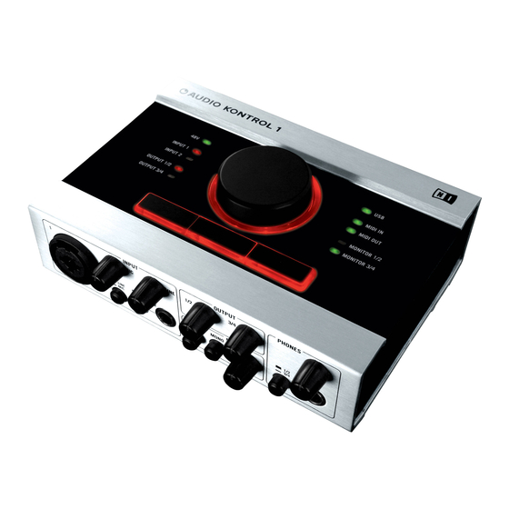
- Page 10 The AUDIO KONTROL 1 Front Panel. 1: Combo Input Jack (Input 1) This analog audio input accommodates either XLR or phone plugs. The XLR plug (mono balanced) allows you to connect a microphone, routing the signal through the mic preamp. The phone plug (¼” jack, TRS mono balanced) allows you to connect a variety of other line level audio devices (mixer, MIDI sound module etc.).
- Page 11 (Line: switch pushed out). If you connect a guitar or bass (for use with GUITAR RIG 3 LE for instance; see section 5.3), select high impedance (Inst: switch pushed in). AUDIO KONTROL 1 – 11...
- Page 12 This switch, when activated (pushed in), merges the two inputs into one mono signal for monitoring. This can be useful, for example, if you’re using only one input on your AUDIO KONTROL 1: you can then monitor this input signal both on the left and right channels.
- Page 13 This knob adjusts the volume of the headphone output. 3.1.2. Rear Panel The AUDIO KONTROL 1 rear panel is equipped with the connections that you won’t necessarily change for each new project. These include the main audio outputs, the MIDI input/output and the USB2 connection. It includes also the phantom power switch for the microphone input.
- Page 14 These connectors allow you to connect MIDI devices to your computer and to send/receive MIDI messages. 16: USB2 Connector Use this connector to connect the AUDIO KONTROL 1 to your computer. 17: Main Outputs Jacks (1 to 4) These analog audio outputs accept phone plugs (¼” jack, TRS mono balanced).
- Page 15 Whereas the front and rear panel deal with audio and MIDI signals, the AUDIO KONTROL 1 top panel is dedicated to the manual controls. It provides you with a set of four Controllers which act like a remote control for your computer applications.
- Page 16 The AUDIO KONTROL 1 Top Panel. AUDIO KONTROL 1 – 16...
- Page 17 19: Controller Knob, 20: Left Button, 21: Middle Button, 22: Right Button The use of these four Controllers will be extensively explained in the next sections. They are the core of the remote control of AUDIO KONTROL 1. 23, 24: Info LEDs These LEDs inform you about various aspects of AUDIO KONTROL 1.
- Page 18 7.2 for more info on how to edit the driver’s parameters. 3.2.2. Mapping Application AUDIO KONTROL 1 lets you control your music applications (or, in fact, any other application) from the four Controllers on the hardware top panel. These Controllers are assigned to specific commands in your target application (for example a key- board shortcut or a MIDI message).
- Page 19 Let’s look at a quick example to understand the remote control signal flow in AUDIO KONTROL 1. When you turn the Controller Knob on the AUDIO KONTROL 1 top panel, the device sends an event through the USB2 connection to your com- puter.
- Page 20 A full set of assignments for the four Controllers is called a Page. The Mapping Application comes with many prepared Pages. These Pages are meant for the most common uses of the Controllers with NATIVE INSTRUMENTS products, major sequencers and other audio applications. You can then customize these Pages and create your own Pages from scratch to fit your needs.
- Page 21 This section quickly describes in a pictorial way some possible uses of AUDIO KONTROL 1 in various setups. We give here only general guidelines, the details to these situations can be found in the sections 5 and 6. Please also note that you can find detailed information about each part of the hardware within section 3.1 above.
- Page 22 RECORDING ROOM set to Mic set to Inst set to 1/2 This setup shows you how to use AUDIO KONTROL 1 in a studio configuration. DJ - INTERNAL MIXER This features: ► All what is needed to record a voice, i.e. a microphone is used with Input 1, and there are two different signals for the control room (headphones, active speakers) and the recording room (headphones).
- Page 23 This setup can be used with the included NATIVE INSTRUMENTS product TRAKTOR 3 LE. It allows you to execute sophisticated mixes using only a computer, AUDIO KONTROL 1, a headphone and an amplification system. This setup is used in the Quickstart of section 5.2 where you will find detailed information.
- Page 24 DJ setup. The only difference is that your mixer gets its inputs from AUDIO KONTROL 1 instead of turntables. TRAKTOR 3 LE can also handle this setup. Please refer to the separate manual of TRAKTOR 3 LE for detailed information.
- Page 25 Inst set to 1/2 The AUDIO KONTROL 1 software bundle includes the great GUITAR RIG 3 LE, putting a selection of great guitar amps and guitar-specific effects into your com- puter. This setup shows you how to play them from your electric guitar. You can use a microphone at the same time.
- Page 26 (see below). The driver installer will ask you to connect the Controller at the proper time. To start the installation, insert the AUDIO KONTROL 1 CD into the optical drive. Open the Windows® Explorer (the Finder on the Mac®) and double-click the CD to see the files on the CD-ROM.
- Page 27 In most cases you can simply accept the default choices for each of these (unless you have some reason for changing them). The installation process of the AUDIO KONTROL 1 Driver will ask you to connect your hardware at some point. Please follow the given instructions closely.
- Page 28 After the installation of all selected packages is completed and the computer has been re-booted you can start using AUDIO KONTROL 1 by connecting it to your audio environment. However, there are five steps that are recommended to do before you begin to make music: ►...
- Page 29 4.3. Configuring Third-Party Software 4.3.1. The MIDI ports of AUDIO KONTROL 1 AUDIO KONTROL 1 contains one MIDI input port and one MIDI output port on the hardware side. However, when you configure your software applications to interact with the AUDIO KONTROL 1 hardware, you will note that the driver offers a second MIDI input/output pair.
- Page 30 Click OK to close the Sounds and Audio Devices dialog. 4.3.3. Using AUDIO KONTROL 1 as the default audio interface in Mac OS® X To use AUDIO KONTROL 1 as your default audio interface under Mac OS® X, do the following: ►...
- Page 31 4.3.4. Configuring Cubase® or Cubase® LE with AUDIO KONTROL 1 (ASIO™) To configure Cubase® or Cubase® LE with AUDIO KONTROL 1, do the following: ► From the Devices menu, select Device Setup. The Device Setup dialog pops ► In the Devices list, on the left, click VST Audiobay.
- Page 32 Also, please make sure that you have carefully read section 3.1, which describes and explains every socket and control found on the AUDIO KONTROL 1 hardware. In the following you will learn how use the AUDIO KONTROL 1 for remotely control- ling the applications delivered alongside the AUDIO KONTROL 1 software.
- Page 33 Besides being able to receive MIDI notes from a keyboard, KORE PLAYER can also utilize MIDI Continuous Controller information (shortened MIDI CC). As the AUDIO KONTROL 1 can send such information, you can use it to conveniently access parameters in KORE PLAYER from the AUDIO KONTROL 1’s Knob and Buttons.
- Page 34 Before you can use AUDIO KONTROL 1 to control KORE PLAYER, you need to select its entry from the Input Menu. To make a MIDI device available within KORE PLAYER, do the following: ► Start KORE PLAYER. ► In KORE PLAYER, load a KoreSound® by dragging it from the Search Results List onto the Global Controller.
- Page 35 From the Input Menu, select the “Audio Kontrol 1 Virtual MIDI In” entry. You have just selected the AUDIO KONTROL 1 as the MIDI remote control device for KORE PLAYER. Now there’s only one thing left to do: you need to tell KORE PLAYER which of its actions you want to control from the AUDIO KONTROL 1.
- Page 36 If you hold down the Right Button and press the Left Button or the Middle Button, this will change the state of KORE PLAYER’s Parameter Buttons 5 or 6, respectively. To load the KORE PLAYER Controller Page for AUDIO KONTROL 1, do the fol- lowing: ►...
- Page 37 KORE PLAYER should reflect this action and change its state each time you press the Left Button. Now turn the AUDIO KONTROL 1’s Knob while you play some notes and listen how the sound changes as the Sound Variation Morph moves across the Sound Variation Grid.
- Page 38 TRAKTOR 3 LE interface; it can only be controlled via MIDI – and now via AUDIO KONTROL 1. Like it says, this parameter is a fine pitch adjustment, much more precise than the Tempo Knob that you see on each Deck.
- Page 39 5.3. Controlling GUITAR RIG LE We will now move to another musical world: the electric guitar and bass empire. Following the multi-functional concept driving AUDIO KONTROL 1, we included the GUITAR RIG 3 LE software. Equipped with some of the best amps and effects from the award-winning GUITAR RIG 3 software, GUITAR RIG 3 LE puts a world of studio-quality guitar and bass sounds at your fingertips.
- Page 40 Now let’s set all this up. We will follow the guidelines provided by the picture in section 4.1.4. AUDIO KONTROL 1 – 40...
- Page 41 As an example, we will use the first two outputs on AUDIO KONTROL 1’s rear panel, as depicted in section 4.1.4. If you did not do it yet, connect the Main Output Jacks 1 and 2 on the hardware’s rear panel to your power amplification system.
- Page 42 Click on the Routing Tab. In the Inputs Tab, connect GUITAR RIG LE’s inputs to AUDIO KONTROL 1’s inputs (actually only Input 2, in our case). In the Outputs Tab, connect the outputs to those physical outputs used on the AUDIO KONTROL 1’s hardware (in our case Outputs 1 and 2).
- Page 43 ► Click “OK” to close the dialog box. Now you need to select the NI AUDIO KONTROL 1 Control Page that is copied to your hard disk during the Guitar Rig 3 LE installation procedure. Navigate to the Options inside GUITAR RIG 3 LE’s Sidekick and enter the Controller Assignments section.
- Page 44 On the right, click on the Page Select menu and select, the entry “NI Guitar Rig 3”. The Mapping Application automatically loads that Page and you will see all its assignments in the rest of the window. AUDIO KONTROL 1 – 44...
- Page 45 As shown on the Mapping Application, this Page is quite simple. It implements only four controls, corresponding to the following GUITAR RIG 3 LE parameters, now accessible from the hardware’s top panel: Let’s play now with the AUDIO KONTROL 1 hardware top panel: ► The Controller Knob drives the Output Volume.
- Page 46 DJing in a club. It is just about listening to music. For that, AUDIO KONTROL 1 will take control of your favorite audio player and bring its main commands right to your fingertips. We assume here that you are using Winamp®...
- Page 47 That was it on the hardware side. On the software side, the operating system needs to use the AUDIO KONTROL 1 as its default interface, as Winamp® and iTunes® are simply relying on the operating system’s settings. The necessary steps to set up AUDIO KONTROL 1 as your default audio interface are described in sections 4.3.2 (Windows®) and 4.3.3 (Mac®).
- Page 48 These four quickstarts showed you the basics of AUDIO KONTROL 1. But the next section will explain some more complex situations, in which AUDIO KONTROL 1 can considerably improve both efficiency and quality in your workflow. AUDIO KONTROL 1 – 48...
- Page 49 Section later in this manual. 6.1. Recording Vocals The first use case that we will look at is recording a voice. AUDIO KONTROL 1’s audio interface allows you to make high quality voice recordings, assuming of course that you have a microphone that is good enough to achieve this… AUDIO KONTROL 1 comes with enough connections to set up an efficient voice-recording configura- tion.
- Page 50 Depending on the type of microphone you use for your recording, the Phantom Power Switch needs to be activated. You can find it on the rear panel of AUDIO KONTROL 1. Please have a look into your microphone’s documentation if you are not sure whether to use phantom power or not.
- Page 51 The basic recording functions are generally quite similar in all of them. We want to specify in the recording software that the main mix has to be sent to AUDIO KONTROL 1’s outputs 3 and 4. To do so, we have to configure the virtual busses in the recording software.
- Page 52 Monitoring, ie listening to the input signal during recording, can be done in three different ways: ► within your recording software, ► externally, via the Direct Monitoring facilities on AUDIO KONTROL 1’s hard- ware, ► by using ASIO™ Direct Monitoring, which is a mixture of the first rwo me- thods.
- Page 53 The potential issue with this type of monitoring is that the monitoring signal will be delayed according to the input latency value of AUDIO KONTROL 1. Depending on the CPU power of your system, it might become problematic in some situations.
- Page 54 Direct Monitoring through AUDIO KONTROL 1 AUDIO KONTROL 1 provides you with its own monitoring facilities. This solution has some advantages: ► You can control it directly on the hardware. ► The monitor signal is not affected by any potential latency issue.
- Page 55 6.1.4 ASIO™ Direct Monitoring ASIO™ Direct Monitoring is a combination of the two former methods. The monitor- ing is done directly in AUDIO KONTROL 1, so that the monitoring signal doesn’t pass through your recording software (thus avoiding potential latency issues), but you can still activate the monitoring from within the recording software, also giv- ing you the benefit of its various monitoring modes.
- Page 56 6.1.4. Checking the Levels First, we have to set the input level on the AUDIO KONTROL 1 audio interface. This is done via the Microphone Input Sensitivity Knob (labeled “Mic” on the hardware’s front panel). The goal is to achieve the highest input level possible (in order to get the highest dynamic range and the lowest noise in your recording), but not so loud that clipping at the A/D converter occurs.
- Page 57 6.2. Controlling a Sequencer - Creating Assignments with Key Commands We will now look at two other cases, in which AUDIO KONTROL 1’s Remote Control allows you to pilot your music software as you wish. The first case deals with a sequencer application. Major sequencers are huge pieces of software with hundreds of functions.
- Page 58 The Right Button sets the cursor back to zero (shortcut: “.” on the numeric keypad). This set of assignments is definitely transport-oriented: from AUDIO KONTROL 1’s hardware top panel, you have access to all major transport actions in Cubase® LE. This allows you, for instance, to focus your mouse actions on the mixer or on the plug-ins.
- Page 59 Page: it does not have any specific action in Cubase® LE, but instead it changes the actions of the other Controllers in Cubase® LE. Because this Left Button is set to Modifier mode, the Left Layer (the second tab on the left) is available. AUDIO KONTROL 1 – 59...
- Page 60 Left Button Middle Button Right Button Start/Stop Main Layer MIDI CC 1 Modifier Record (Numpad) (Space) Cycle On/Off Cursor at Zero Left Layer MIDI CC 1 (Numpad /) (Numpad,) Middle Layer Zoom In/Out Right Layer (H/G) AUDIO KONTROL 1 – 60...
- Page 61 Note: If you change the keyboard shortcuts in your target application, AUDIO KONTROL 1 mappings won’t be updated! They only send key com- mands. Please check that these key commands are the one you need in your target application. Moreover, major sequencers often allow you to create whole sets of key commands for different tasks.
- Page 62 Moreover, AUDIO KONTROL 1’s ability to seamlessly mix both MIDI and key commands allow you to design very efficient controlling schemes. If you are using a MIDI controller anyway, the AUDIO KONTROL 1’s hardware top panel can still be a very useful additional control device for the most important functions in your software.
- Page 63 In this case, we will use KORE PLAYER, included in the AUDIO KONTROL 1 bundle. As mentioned earlier in this manual, a Factory Page for KORE PLAYER is readily available. Most importantly, KORE PLAYER needs to be connected to both the MIDI input ports that AUDIO KONTROL 1 provides.
- Page 64 Layer tabs on the left, you can select the assignments for that Layer. By then clicking on one of the four Controller Areas (or on one of the four upper tabs), you can select the particular assignment for the corresponding Controller. AUDIO KONTROL 1 – 64...
- Page 65 MIDI-capable program running on the computer can receive it as long as it listens to both MIDI ports of AUDIO KONTROL 1. If you want to be sure that only one program responds to this message, set the channel number in the Mapping Application and in your programs accordingly.
- Page 66 Button does something, while releasing it doesn’t. For detailed information about all possible assignment types, please refer to the Reference section later in this manual. The mappings for the “NI Kore Player” Page can be summarized in the following table: AUDIO KONTROL 1 – 66...
- Page 67 Main Layer (no Button held) only controls the overall Volume ► the Left Layer (Left Button held) controls some Chorus parameters ► the Middle Layer (Middle Button held) controls some Delay parameters ► the Right Layer (Right Button held) controls some Reverb parameters AUDIO KONTROL 1 – 67...
- Page 68 Let’s quickly look at the different assignment parameters. From top to bottom, in both the left and right parts of the Definition Area, we find: The left part of the Definition Area for the Controller Knob on the Middle Layer for the Page “MIDI Demo Page”. AUDIO KONTROL 1 – 68...
- Page 69 Definition Area, to avoid any unpleasant surprises. In both left and right parts, we need to modify the Event Label field as well, so it reflects the new actions. The Definition Area should now look like this. AUDIO KONTROL 1 – 69...
- Page 70 Chorus tab to see what happens. Now press and hold the Middle Button on your AUDIO KONTROL 1 hardware (thus selecting the Middle Layer mappings), and move the Controller Knob back and forth. You should see the Speed parameter moving accordingly.
- Page 71 Step Size (with the arrows or by dragging the mouse). The Middle Layer should now look like this: Knob Left Button Middle Button Right Button Decrease Reverb Increase Reverb Middle Layer Chorus Speed Color Color AUDIO KONTROL 1 – 71...
- Page 72 Program Change message type, “PC fixed”, and set a particular Program Change number corresponding to the Preset you want to have at your disposal at any time. Feel free to try other assignments, AUDIO KONTROL 1 offers you endless map- ping possibilities! AUDIO KONTROL 1 – 72...
- Page 73 AUDIO KONTROL 1 from within another program (e.g. a sequencer, or Winamp®/ iTunes®). You only need to tell the program to use the AUDIO KONTROL 1 inter- face. Examples of that process are given in the quickstarts (section 5) above.
- Page 74 Presets: Several Presets are included, from minimal latency suitable for fast systems that don’t tax the CPU load heavily, to higher latencies suitable for slower systems or fast systems with heavy CPU loads. Experts can also choose User Defined Settings (see next). AUDIO KONTROL 1 – 74...
- Page 75 USB buffer. Together the para- meters define the system‘s latency, i.e. the time that passes from when a audio signal is sent into the AUDIO KONTROL 1 hardware, manipulated digitally by the computer and sent back to the hardware‘s outputs. Note that the USB Buffersize parameter has a very strong effect on the CPU usage of the system.
- Page 76 4.3.3. 7.3. Remote Control Basic Concepts In order to fully understand how AUDIO KONTROL 1’s remote control works, and to be able to use it at maximum capacity, it is necessary to explain the basic concepts of AUDIO KONTROL 1’s workflow concerning its remote controlling scheme.
- Page 77 Knob movement exceeds a certain threshold, a hardware event is generated, either “Rotate Left” or “Rotate Right”. If the Controller Knob is moved further in the same direction, after the same amount of rotation a subsequent “Rotate Left/Right” event is generated. AUDIO KONTROL 1 – 77...
- Page 78 The Modifier Mode is only available in the Main Layer. This means in par- ticular that you cannot use modifier combinations to define a hardware event (as you could on a computer keyboard with e.g. Ctrl+Shift+A). AUDIO KONTROL 1 – 78...
- Page 79 Configuration with 0 modifiers (upper left): Each Controller can create a pair of hardware events (rotate left/right or button pressed/released), thus creating all in all 4 pairs of possible hardware events. There is only one Layer, the Main Layer. AUDIO KONTROL 1 – 79...
- Page 80 Controller Knob, Left and Right Buttons. That makes a total of 2+3+3 = 8 pairs of possible hardware events. Once again, you could have chosen another set of two Buttons as modifiers. AUDIO KONTROL 1 – 80...
- Page 81 Example: If this configuration with three Buttons as modifiers still seems strange to you, look at this small example. Imagine that you are working on a 3-track project in your favorite sequencer. By correctly setting up your AUDIO KONTROL 1 Mapping Application, you could use AUDIO KONTROL 1’s hardware like follows: ►...
- Page 82 Layers. It’s a key concept, which allows you to multiply the assignment possibilities of your AUDIO KONTROL 1. Some of the quickstarts (section 5) and Use Cases (sections 6) show examples of using this Modifier mode.
- Page 83 Now let’s take a short break and try to sum up what we’ve just learned about the remote control signal flow. The AUDIO KONTROL 1 hardware transmits your commands in the form of hard- ware actions. These hardware actions are transformed into hardware events, depending on how the actions should be interpreted (which Controllers are manipulated, on which Layer, in which Mode…).
- Page 84 It stores the links between hardware actions (what you do on AUDIO KONTROL 1 top panel) and software events (what you want to be done within a specific piece of software). Here we will systematically describe all ele- ments of the Mapping Application user interface that controls and organizes the formerly explained hardware and software actions/events and other Layers.
- Page 85 Application Control Bar). For more info in the Driver Control Panel, see section 7.2. ► Exit: Quits the Mapping Application. Note that the AUDIO KONTROL 1’s top panel remote control will then be deactivated, since it needs the Mapping Application to be running in order to function properly.
- Page 86 AUDIO KONTROL 1 logo). This dialog contains valuable information about the software such as the version number. ► Visit AUDIO KONTROL 1 on the web: Opens in your internet browser the AUDIO KONTROL 1 page on the NATIVE INSTRUMENTS website. 7.4.2. The Application Control Bar The Application Control Bar is always visible.
- Page 87 Each Page is stored as a separate XML file. Pages are of two types: ► AUDIO KONTROL 1 comes with an extensive set of prepared Factory Pages for various NATIVE INSTRUMENTS products, major sequencers and multimedia applications. These Pages cannot be edited.
- Page 88 AUDIO KONTROL 1 Logo and NATIVE INSTRUMENTS Logo Clicking on the AUDIO KONTROL 1 Logo or on the NATIVE INSTRUMENTS Logo opens the About dialog. This dialog contains valuable information about the software such as the version number. 7.4.3. The Display View The Display View allows you to see what the current assignations are for the four Controllers on your AUDIO KONTROL 1 top panel.
- Page 89 The Display View consists of two areas: The lower Hardware Area displays the AUDIO KONTROL 1 hardware top panel. In the upper Information Area, information text is displayed, depending on the mouse position within the Hardware Area. If you position the mouse over one of the elements in the Hardware Area, the Information Area will update to display all mapping information for this particular Controller.
- Page 90 (e.g., Toggle, Rotate) as well as both Event Labels (e.g. On: Activate Reverb; Off: Deactivate Reverb). They can be selected via the mouse. When a Controller Area is selected, the corresponding element’s settings are displayed in the lower Definition Area. AUDIO KONTROL 1 – 90...
- Page 91 Rotate: Left on the left side, Right on the right side. ► Toggle: On on the left side, Off on the right side. ► Trigger: Press on the left side, Release on the right side. AUDIO KONTROL 1 – 91...
- Page 92 Event to be executed. Depending on the Software Event Type selected in the previ- ous menu, the Specification Area provides different elements. If Off is selected in the Software Event Type menu, the Specification Area is dis- abled: No Specification Area if Off is selected. AUDIO KONTROL 1 – 92...
- Page 93 Mapping Application stores it, with the cor- responding modifier keys. These modifier keys are Shift, Ctrl, Alt and Win on Windows® systems and Shift, Ctrl, Alt and Apple® on the Mac®. AUDIO KONTROL 1 – 93...
- Page 94 MIDI messages needs to be connected to that virtual MIDI port - make sure that the target software’s MIDI interface is setup correctly. Specification Area for the MIDI Software Event Type. AUDIO KONTROL 1 – 94...
- Page 95 Pitch and Pressure. The Pitch menu offers an All entry: If this entry is selected, MIDI Channel Pressure messages are sent; in all other cases Polyphonic Key Pressure messages are sent. AUDIO KONTROL 1 – 95...
- Page 96 (with the mouse for example), the target application will not communicate this to the Mapping Application. A subsequent CC Internal message trig- gered with AUDIO KONTROL 1 might therefore cause a sudden jump of the controller value! AUDIO KONTROL 1 – 96...
- Page 97 Channel Mode: Sends a MIDI Channel Mode message. A dropdown menu selects whether this message is an All Sound Off message, an All Notes Off message, or both combined. This can be useful as a Panic Button. AUDIO KONTROL 1 – 97...
- Page 98 MIDI real-time messages. In Extended mode subsequent messages can also be learnt; in all other cases, a new message overwrites the previ- ous setting.To switch the MIDI Learn mode off, click on the Learn switch again. AUDIO KONTROL 1 – 98...
- Page 99 7.5. Add-on Software AUDIO KONTROL 1 features three great products by NATIVE INSTRUMENTS: KORE PLAYER (including the KORE SELECTION SOUNDPACK), GUITAR RIG 3 LE and TRAKTOR 3 LE, plus a complete recording-sequencing solution, Cubase® LE by Steinberg. All are part of the software package, along with the Mapping Application.
- Page 100 Verify that you have installed the latest driver and the latest software update. Check the NATIVE INSTRUMENTS website for information. ► Make sure that the AUDIO KONTROL 1 hardware is connected to a USB 2.0 port on your computer. ►...
- Page 101 On a PC in the Windows® Start menu there should be a new entry called “Native Instruments AUDIO KONTROL 1 Driver”. There you will find the helper applications “Audio Statistics” and “Control Panel”. Make sure that the AUDIO KONTROL 1 is connected to the computer and open the Control Panel. If all the drop-down menus are grayed out (i.e., there are no presets in the preset drop-down list, no sample...
- Page 102 Control Panel PC – AUDIO KONTROL 1 connected On Mac OS® X, look into the System Preferences for the NATIVE INSTRUMENTS USB Audio Control Panel icon. Open this control panel to see if the device is found. If no device is found the Control Panel values will appear grayed out. If the NATIVE INSTRUMENTS USB Audio Control Panel icon is missing here, the driver is probably not installed at all.
- Page 103 8.2.1. USB 2.0 required The AUDIO KONTROL 1 is a USB 2.0 interface and will not work at all on a USB 1.0/1.1 port. In addition, although the minimum power specified for a USB 2.0 port is 500 mA, we have seen a few cases where the USB 2.0 ports on certain computers do not fulfill the minimum requirements and therefore do not meet the official USB 2.0...
- Page 104 In order to control an application (e.g. KORE PLAYER) with MIDI messages, the target application needs to be connected to both MIDI ports of the AUDIO KONTROL 1 hardware. Please verify that they are activated correctly within the target application.
- Page 105 8.4.1. Try to eliminate the loop Assuming that you have connected the AUDIO KONTROL 1 to a mixer, a first troubleshooting step is to disconnect all devices from your mixer that you are not currently using.
- Page 106 DI (direct input) box between the AUDIO KONTROL 1 outputs and the mixer inputs. (This is the same kind of box that is used to connect a line-level instrument like a guitar). Most of these boxes have a ground lift switch on them, this can be used to break the ground loop and eliminate the noise.
- Page 107 In case your Computer is unable to handle glitch free audio processing, the tool will show you red latency bars and report this in the box on the bottom. Run it with both settings – AUDIO KONTROL 1 connected and disconnected – to find out about your computer’s capacities.
- Page 108 8.5.4. Disable Devices First, disconnect additional hardware (printers, scanners etc.) that you don’t need while you are working with AUDIO KONTROL 1. Thus, the computer does not need to handle superfluous devices. Beside that, laptops often are equipped with built-in devices that disturb au- dio processing.
- Page 109 Mac OS® X If you have a wireless LAN card installed and Bluetooth® running turn them off while you are using AUDIO KONTROL 1 (you can turn this off in the top OSX menu bar). AUDIO KONTROL 1 – 109...
- Page 110 9. Appendix 9.1. Technical Specifications and Block Diagram AUDIO KONTROL 1 – 110...
- Page 111 Full Scale Level -40 dBu at maximum Gain Maximum Input Level: +10 dBu SNR (weighted): 100 dB Equivalent Input Noise: -128 dBu (weighted) THD+N: 0.007% Frequency Response: 20 - 20000 Hz (+0 / -0.5 dB) AUDIO KONTROL 1 – 111...
- Page 112 16, 24 Bit Converter Cirrus Logic® Line Outputs 100 Ohms unbalanced, Output Impedance: 200 Ohms balanced Maximum Output Level: +13 dBu SNR (weighted): 103 dB THD+N: 0.005% Frequency Response: 20 - 20000 Hz (+0 / -0.5 dB) AUDIO KONTROL 1 – 112...
- Page 113 20 - 20000 Hz (+0 / -0.5 dB) Other Interfaces Interface to computer: USB 2, bus powered MIDI: 1 Input, 1 Output Control Elements Endless Knobs: Buttons: Dimensions Height: 52 mm Width: 150 mm Depth: 123 mm Weight: 400 g AUDIO KONTROL 1 – 113...
- Page 114 Effect Control 2 0-127 Undefined 0-127 Undefined 0-127 General Purpose Controller 1 0-127 General Purpose Controller 2 0-127 General Purpose Controller 3 0-127 General Purpose Controller 4 0-127 Undefined 0-127 Undefined 0-127 Undefined 0-127 Undefined 0-127 AUDIO KONTROL 1 – 114...
- Page 115 LSB for Control 14 (Undefined) 0-127 LSB for Control 15 (Undefined) 0-127 LSB for Control 16 (General Purpose Controller 1) 0-127 LSB for Control 17 (General Purpose Controller 2) 0-127 LSB for Control 18 (General Purpose Controller 3) 0-127 AUDIO KONTROL 1 – 115...
- Page 116 >64 Legato <63 off, >64 Hold 2 Sound Controller 1 (default: Sound Variation) 0-127 Sound Controller 2 (default: Timbre/Harmonic Intens.) 0-127 Sound Controller 3 (default: Release Time) 0-127 Sound Controller 4 (default: Attack Time) 0-127 AUDIO KONTROL 1 – 116...
- Page 117 Effects 5 Depth 0-127 Data Increment (Data Entry +1) Data Decrement (Data Entry -1) Non-Registered Parameter Number (NRPN) - LSB 0-127 Non-Registered Parameter Number (NRPN) - MSB 0-127 Registered Parameter Number (RPN) - LSB 0-127 AUDIO KONTROL 1 – 117...
- Page 118 Undefined Undefined Undefined Undefined Undefined Undefined Undefined Undefined Undefined Undefined Undefined Undefined Undefined Undefined The Controller numbers 120-127 are reserved for Channel Mode Messages, which rather than controlling sound parameters, affect the channel‘s operating mode. AUDIO KONTROL 1 – 118...
Need help?
Do you have a question about the AUDIO KONTROL 1 and is the answer not in the manual?
Questions and answers