Table of Contents
Advertisement
Advertisement
Table of Contents

Related Manuals for McIntosh MAC 4100


Summary of Contents for McIntosh MAC 4100
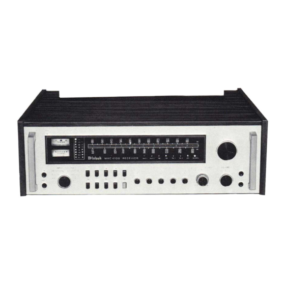
- Page 1 THE MCINTOSH MAC 4100 RECEIVER Price $2.00 Reading Time: 48 Minutes...
- Page 2 HAZARD, DO NOT EXPOSE THIS UNIT TO RAIN OR MOISTURE. The Mclntosh you have purchased is a Model MAC 4100. It has a serial number located on the rear panel of the chassis. Record that serial number here: Serial Number The model, serial number and purchase date are im- portant to you for any future service.
-
Page 3: Table Of Contents
Your MAC 4100 Solid State AM- FM/FM Stereo Receiver will give you Contents many years of pleasant and satisfactory performance. If you have any questions, please contact: CUSTOMER SERVICE Mclntosh Laboratory Inc. INTRODUCTION ...2 2 Chambers Street INSTALLATION.. .3 Binghamton, New York 13903 HOW TO CONNECT...5... -
Page 4: Introduction
Introduction tinuously assured by POWER GUARD. The POWER The Mclntosh MAC 4100 is a high quality, high GUARD circuit dynamically prevents power power AM/FM Stereo Receiver. Its design has been governed by insistence on great flexibility, sensitivi- amplifiers from being overdriven into hard clipping -- ty, high performance with long life. -
Page 5: Installation
Remove these 4 screws. Save the screws to reinstall the The MAC 4100 may be used on a shelf or table top metal top after removal of the enclosure top in the enclosure in which it comes or may be install- panel. - Page 6 FOR 1/2" SHELF USE 1 1/4" SCREW (1.3cm) (3.2cm) PLASTIC BUTTONS FOR 3/4" SHELF USE 1 1/2" SCREW (1.9cm) (3.8cm) CUTOUT FOR MOUNTING VENTILATION PANEL SECURE UNIT WITH SCREW AND WASHER Fig. 3 MAC 4100 Custom Mounting Profile Fig. 4 MAC 4100 Enclosure Assembly...
-
Page 7: How To Connect
There are three types of AC power outlets on the Connect the cable from the left channel of the turn- back panel of the MAC 4100 one red. two black, and table into the INPU1 L PHono 1 jack. two green... - Page 8 50 to 150 feet in length. Sus- switch positions. pend the wire in a straight line as high as possible. MAC 4100 receivers with serial numbers below Attach the wire at each end with suitable glass or BY3000 do not have the FM preselector switch ceramic insulators.
- Page 10 Added resis- CONNECTING ONE LOUDSPEAKER FOR MONO tance causes reduction of damping characteristics, The left and right outputs of the MAC 4100 must con- modification of frequency response and reduction in nect to separate loudspeakers. Do not parallel the power output.
-
Page 12: What The Front Panel Controls Do And How To Use Them
2 on the rear panel are automatically transferred to The MAC 4100 is designed so it may be used with the front panel. The tape recorder plugged into the two tape recorders. The four upper left pushbuttons... - Page 13 ed off. The POWER ON pushbutton controls the AC heard from the speakers. In this position a copy of power for any source other than the turntable. the program on tape recorder 1 can be made on tape recorder 2. To monitor the original use MONITOR In the MANUAL position only the POWER ON TAPE 1 pushbutton and to monitor the copy use pushbutton will turn receiver AC power on or off.
-
Page 14: Front Panel Indicators
SPEAKER switches. Front Panel indicators The MAC 4100 has three dial scales: SIGNAL STRENGTH METER When tuning either an FM or AM signal the signal 1. AM - marked 550 to 1600 kHz strength meter indicates the strength of the signal 2. -
Page 15: Balancing Your Stereo
A Mcln- tosh advancement helps to protect your speaker from this kind of damage. The MAC 4100 has a built in "waveform comparator" that compares the wave The two remaining LEDs indicate AFL and FM shape of the input signal with the output signal. - Page 16 When the 19 kHz pilot signal for stereo transmission is received the automatic circuitry switches the MAC 4100 to stereo and the FM MPX LED indicator is turned on. If the FM station is" not broadcasting a 19 kHz pilot signal the FM MPX Indicator will remain off and the tuner will automatically switch to mono.
-
Page 17: Mac 4100 Performance Limits
MAG 4100 Performance Limits TAPE OUTPUT We promise you that the MAC 4100 you buy is Tuner: 1.0 V a t 100% modulation [FM] capable of performance at or exceeding these limits Tape: 250 mV with rated input at the time of purchase or you get your money back. -
Page 18: Technical Description
MECHANICAL INFORMATION IMAGE REJECTION SIZE: 80 dB IHF minimum In cabinet: 18-5/8 inches (473.1mm) wide, 6-1/2 in- ches (165.1mm) high, 15-1/2 inches (393.7mm) deep. STEREO SEPARATION Without cabinet: Front panel measures 17-9/16 in- 45 dB minimum at 1 kHz ches (446.1mm) wide by 5-1/4 inches (133.4mm} high. Chassis measures 17-1/8 inches (435mm) wide by SCA REJECTION 4-15/16 inches (125.4mm) high by 13-1/2 inches... - Page 19 19 kHz pilot tone. The 228 kHz formance over 180 degrees. Each MAC 4100 feeds a 3 stage Johnson counter via a binary divider loopstick is individually tuned for optimum perfor- to generate a series of square waves.
- Page 20 The MAC 4100 uses active circuitry. The shorting of the output. When the MAC 4100 operates same type of integrated circuit operational amplifier normally the SENTRY MONITORING CIRCUIT has that is used in the phono amplifier is used here.
- Page 21 Three additional electronically regulated power duce more power output than it can deliver with low supplies are used in the MAC 4100; a + 12 volt sup- distortion. A clipped amplifier can have more than ply for the FM front end, and a + 18 volt supply and a 40% harmonic distortion.
-
Page 22: Performance Charts
Performance Charts POWER OUTPUT SECTION HARMONIC DISTORTION VS POWER RL = 8 OHMS, BOTH CHANNELS OPERATING POWER OUTPUT IN WATTS POWER OUTPUT SECTION BOTH CHANNELS OPERATING .05% THD POWER BANDWIDTH FREQUENCY Hz OUTPUT SIGNAL WAVEFORM SHOWING ACTION OF POWER GUARD TO ELIMINATE OUTPUT SIGNAL INTERMODULATION DISTORTION CLIPPING. - Page 23 FM SIGNAL PERFORMANCE SIGNAL INPUT IN MICROVOLTS F.M. FREQUENCY RESPONSE AND STEREO SEPARATION FREQUENCY IN HERTZ F.M. HARMONIC DISTORTION 100% MODULATION FREQUENCY IN HERTZ...
- Page 24 AM MINIMUM USABLE SENSITIVITY (IHF) FREQUENCY IN kHz A.M. FREQUENCY RESPONSE 80% Modulation FREQUENCY IN HERTZ AM SELECTIVITY AT 1000 kHz FREQUENCY IN kHz...
- Page 25 LOUDNESS RESPONSE FREQUENCY IN HERTZ FREQUENCY RESPONSE OF EQUALIZER FREQUENCY CONTROLS SET AT MAXIMUM AND MINIMUM FREQUENCY IN HERTZ...
- Page 27 MCINTOSH LABORATORY INC. 2 CHAMBERS ST., BINGHAMTON, N.Y. 13903 607-723-3512 The continuous improvement of its products is the policy of Mclntosh Laboratory Incorporated who reserve the right to improve design without notice. Printed in U.S.A. 039222...
Need help?
Do you have a question about the MAC 4100 and is the answer not in the manual?
Questions and answers