Panasonic WJ-FS616 Operating Instruction
Video multiplexer
Hide thumbs
Also See for WJ-FS616:
- Operating instructions manual (62 pages) ,
- Service manual (41 pages)

Related Manuals for Panasonic WJ-FS616


Summary of Contents for Panasonic WJ-FS616
- Page 1 Video Multiplexer WJ-FS616 Before attempting to connect or operate this product, please read these instructions completely...
- Page 2 If you lose the fuse cover the plug must not be used until a replacement TO REDUCE THE RISK OF ELECTRIC SHOCK, cover is obtained. DO NOT REMOVE COVER (OR BACK), NO USER A replacement fuse cover can be purchased from your local Panasonic SERVICEABLE PARTS INSIDE. Dealer. REFER SERVICING TO QUALIFIED SERVICE IF THE FITTED MOULDED PLUG IS UNSUITABLE FOR THE SOCK- PERSONNEL.
-
Page 3: Table Of Contents
CONTENTS PREFACE ....................................2 FEATURES ....................................2 PRECAUTIONS ..................................3 MAJOR OPERATING CONTROLS AND THEIR FUNCTIONS ....................4 INSTALLATIONS ..................................11 SYSTEM CONNECTIONS ............................... 15 SETUP MENU ..................................21 Setup Menu ..................................22 Alarm Setup Menu ................................23 Multiscreen Output Menu ..............................25 Spot Output Setup ................................ -
Page 4: Preface
The pattern of a 4, 7, 9, 10, 13, or 16 multiscreen Time Lapse VTR. sequence consisting of up to 5 steps can be pro- grammed as shown below. • The WJ-FS616 can be controlled from a PC or the WV-CU550A System Controller via RS-232C or RS- 485 interface. 2 sec. -
Page 5: Precautions
PRECAUTIONS • Refer all work related to the installation of this • Do not expose the appliance to water or product to qualified service personnel or system moisture, nor try to operate it in wet areas. installers. Do take immediate action if the appliance becomes wet. -
Page 6: Major Operating Controls And Their Functions
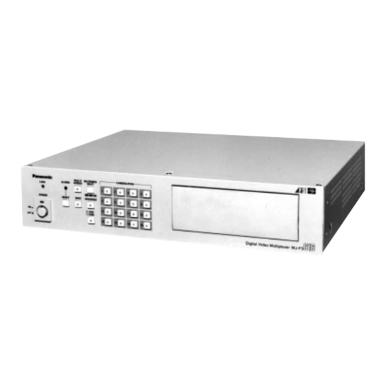
MAJOR OPERATING CONTROLS AND THEIR FUNCTIONS Video Multiplexer WJ-FS616 <Front View> CAMERA/PRESET POSITION MULTI MULTISCREEN PUSH OPEN ALARM SCREEN SELECT LOCK POWER RESET SPOT SEQUENCE CURSOR / CAMERA CONTOROL FUNCTION I R I S SET UP/ESC LOCK CLOSE OPEN VTR CONTROL... - Page 7 5. Spot Monitor Button (SPOT) 21. Function Button (FUNCTION) This button is used to operate the spot monitor con- This button is used to display the VTR playback nected to the SPOT OUT connector. picture with the camera pictures on the multiscreen The LED (Green) in the button lights up to indicate monitor.
- Page 8 30. Zoom Control Buttons (ZOOM, TELE / WIDE) 33. VTR Control Buttons These buttons are used to adjust the lens zoom of These buttons are used for remote control of the the specified lens mounted on the camera. VTR that is connected to the Video Multiplexer. The buttons function as shown below.
- Page 9 49. Record Output Connector (REC OUT, VIDEO / S-VIDEO) The recording signal for the time lapse VTR is pro- vided via this connector. This connector can also be used as multiscreen output 2 with the specified conditions. 50. Playback Input Connector (PLAY IN, VIDEO/ S-VIDEO) The playback signal from the time lapse VTR is sup- plied to this connector.
- Page 10 System Controller WV-CU550A Note: When using this controller in combination with the WJ-FS616, cover the panel of the controller with the panel tem- plates provided. SET UP CAMERA CAMERA ALARM BUSY SET ON SET OFF T/L MODE PLAY MULTISCREEN RESET...
- Page 11 Reverse Play Button (REV A) 1. Alarm Indicator (ALARM) This button, used in combination with the Alternate This LED indicator (Red) lights up to indicate that button, activates reverse playback on the Time an alarm condition exists. Lapse VTR. It goes off when the alarm is reset automatically. To turn the indicator off, press the ALARM RESET Play Button (PLAY B) button.
- Page 12 This button is used to display the VTR playback These ports are used to exchange control data with picture with the camera pictures on the multiscreen the WJ-FS616 Video Multiplexer. monitor. During the setup, this button is used to select the 24.
-
Page 13: Installations
WV-PB6164 Data Multiplex Board must be installed in the Video Multiplexer. Four data multiplex boards are included with the WJ-FS616 for cameras 1 to 4. Please note that additional multiplex boards are available for purchase as model WV-PB6164 Data Multiplex Boards, which includes four control boards. - Page 14 6. Set the jumper connector, located at the top left of Tally Output Setting the board to be installed, to the position shown below. Allows you to use the Alarm Input Terminal as Tally Output Terminal by changing two internal connec- tions.
- Page 15 Dummy Black Burst Setting Dip Switch Setting According to the initial factory setting, the Dummy Alarm Output Setting Black Burst signal is supplied to the REC OUT con- nector as needed to overwrite any picture dis- 1. Disassemble the video multiplexer as described for played by error.
- Page 16 WV-CU550A System Controller WJ-FS616 Video Multiplexer Modifying the Front Panel Mounting in the Rack 1. Peel the tape off the supplied panel templates, then 1. Remove the four rubber feet by removing the four attach them on the front panel of the System screws on the bottom of the video multiplexer.
-
Page 17: System Connections
SYSTEM CONNECTIONS Shown below is an example of a basic system connection. Alarm Video Alarm Sensor Data RS-485 Video Multiplexer WJ-FS616 MULTISCREEN CAMERA/PRESET POSITION MULTI PUSH OPEN ALARM SCREEN SELECT LOCK POWER RESET SPOT SEQUENCE RS-232C/Wired Time Lapse VTR Spot Monitor... - Page 18 RS- Note: Make sure that the cable length between the 485 “2-wire twisted pair shielded cable” is camera site and the WJ-FS616 Video Multi- used. plexer is less than 1 200 m (4 000 ft) when Low grade cable will result in unstable opera- using RG-6/U (5C - 2V) or equivalent cables.
- Page 19 DATA IN port of the Video Multiplexer and the other end into DATA OUT port on the System Controller. Video Multiplexer If you use cables assembled from locally procured WJ-FS616 materials, it is important that only high quality, data MULTISCREEN SPOT grade cable, suitable for RS-485 “2-wire twisted...
- Page 20 Connection with Alarm Sensors Connect the sensor switches to the Alarm/Remote (ALARM/REMOTE) Control Connector on the rear of the Video Multiplexer as shown in the example below. Pin No. Designation Pin No. Designation ALARM/REMOTE Function Still Picture Electronic Zoom VTR/Camera Select Sequence Multiscreen Select Spot...
-
Page 21: Connection With The Time Lapse Vtr
Connection with the Time Lapse VTR Connect the Time Lapse VTR as shown in the example below. Video Multiplexer WJ-FS616 CAMERA REC OUT PLAY IN SW IN VIDEO S–VIDEO VIDEO S–VIDEO ALARM/REMOTE Time Lapse VTR VIDEO IN VIDEO OUT S-VIDEO... - Page 22 Connection with External Remote Control Switches Connect the switches (dry contact or open collector input) to the Alarm/Remote (ALARM/REMOTE) Control Connector on the rear of the Video Multiplexer as shown in the example below. Pin No. Designation Pin No. Designation Function Still Picture Electronic Zoom...
-
Page 23: Setup Menu
The SETUP MENU appears on the Spot and EL-ZOOM ( + ): Selects the mode or parameter. Multiscreen Monitors as shown below. FUNCTION: Selects the next page. WJ-FS616 SETUP MENU ALARM SETUP * MULTI OUTPUT SETUP * FUNCTION SPOT OUTPUT SETUP *... -
Page 24: Setup Menu
Setup Menu As shown below, the SETUP MENU has nine main sub menus: Alarm Setup, Multiscreen Output Menu, Spot Output Setup, Record Output Setup, Multiscreen 2 Output Setup, System Setup, Camera Download, Camera Upload and All Reset. Six of these sub menus; Alarm Setup, Multiscreen Output Setup, Spot Output Setup, Record Output Setup, Multiscreen 2 Output Setup and System Setup, are further divided into additional submenus. -
Page 25: Alarm Setup Menu
4. To clear the alarm data, press the LEFT or Alarm Setup Menu RIGHT button to select CLEAR where the cur- sor is positioned, then press the SET button. WJ-FS616 SETUP MENU 5. Press the SETUP/ESC button to return to the ALARM SETUP * previous ALARM SETUP menu. - Page 26 4. Camera Switching Pulse Loss 7. Alarm Buzzer Duration Alarm This item lets you select the ringing duration of the alarm buzzer when alarm is activated. This item lets you enable or disable alarm display on the monitor screen when the camera switching 1.
-
Page 27: Multiscreen Output Menu
9. Alarm Mode on Spot Monitor Multiscreen Output Menu This item lets you select the mode for displaying an alarm on the Spot Monitor. WJ-FS616 SETUP MENU 1. Move the cursor to the ALM MODE-SPT para- ALARM SETUP * MULTI OUTPUT SETUP * meter. - Page 28 2. Clock Display Setting 5. Camera Display Position Setting This item lets you enable or disable the clock dis- This item lets you select the position where the play on the Multiscreen Monitor. camera picture will be displayed on the Multiscreen Monitor.
-
Page 29: Spot Output Setup
Spot Output Setup ON: Enables clock display on the Spot Monitor screen. OFF: Disables clock display on the Spot Monitor screen. WJ-FS616 SETUP MENU ALARM SETUP * After finishing the setting, press the SETUP/ESC MULTI OUTPUT SETUP * SPOT OUTPUT SETUP * button to return to the previous SETUP MENU. - Page 30 2. Clock Display 4. Recording Mode This item lets you enable or disable recording of Move the cursor to REC MODE SETUP, then press the clock display on the VTR. the SET button. The REC MODE SETUP menu appears on the monitor screen as shown below. 1.
-
Page 31: Multiscreen 2 Output Setup
LEFT or RIGHT button. The pictures of the selected cameras are dis- played one after another on the monitor screen. WJ-FS616 SETUP MENU Note: Numbers can also be input directly with ALARM SETUP * the Camera Number Buttons (1 - 10). -
Page 32: System Setup
2. Clock Display Position This item lets you select the position where the clock will be displayed on the Spot Monitor screen. WJ-FS616 SETUP MENU 1. Move the cursor to CLOCK POSITION, then ALARM SETUP * MULTI OUTPUT SETUP * press the SET button. -
Page 33: Sequence Setup
Press the FUNCTION button to display the next Spot Sequence (SEQ1) page, then press this button again to return to This item lets you program or edit a Spot the previous page. Sequence. Up to 32 steps can be assigned in the 2. - Page 34 Preset Position Multi Sequence (SEQ2, SEQ3) This item lets you program or edit a Multi 1. Move the cursor to the step number you want Sequence. Up to 5 steps can be assigned in the to edit in the PRE area by pressing the table shown below.
- Page 35 Dwell Time 6. Sequence Timing (Multiscreen) This item lets you select functions of devices con- 1. Move the cursor to the DWELL TIME parame- nected to pin 26 of the ALARM/REMOTE Control ter. Connector. 2. Select the desired dwell time by pressing the One of these functions is input of the time adjust- LEFT or RIGHT button.
- Page 36 1-16: Communicates with the camera site by 9. Cable Compensation/VD2/Data RS-485. This item lets you select the optimum setting for the This number indicates the unit address of cable-loss compensator and whether to supply the the selected camera. VD2 (sync) signal or control data to the camera. OFF: Disables communication with the camera site.
-
Page 37: Data Mode
2. Move the cursor to the port you want to edit by 11. Data Mode pressing the Direction Arrow Buttons. This item lets you select an external controller from 3. Select the desired Delay Time in the DELAY the data port. area by pressing the Increment (+) or Decrement ( ) button. -
Page 38: Camera Download
15. Daisy Mode Camera Download This item lets you select whether to have the video This item lets you save the camera setup data into signal connected to SPOT IN looped through to the the memory of the Video Multiplexer. SPOT OUT connector (daisy-chain connection). -
Page 39: Camera Upload
Camera Upload All Reset Select This item lets you restore the factory settings with- This item lets you upload camera setup data from out having to go through each individual menu. the Video Multiplexer’s memory to a camera. 1. Move the cursor to ALL RESET SELECT on the 1. -
Page 40: Operating Procedures
OPERATING PROCEDURES Operating the Multiscreen MONITOR CONTROL Monitor FUNCTION The following operations are available on the Before starting the following procedures, all system Multiscreen Monitor. components should be turned on. Then set the LOCK switch to the OFF position. Displaying the Camera Picture Operating the Spot Monitor The following operations are available on the Spot 1. - Page 41 3. Electronic Zooming 1. Repeat the procedures described above for Single Spot. 2. Press the EL-ZOOM button to display the zoomed picture. The LED on the EL-ZOOM button lights up. 4 SEGMENT SCREEN 7 SEGMENT SCREEN 9 SEGMENT SCREEN 10 SEGMENT SCREEN EL-ZOOM ENTRANCE 13 SEGMENT SCREEN...
- Page 42 Displaying the Playback Picture The following procedures are not applicable to the Multiscreen Monitor 2. ENTRANCE 1. Press the MULTISCREEN button. The LED (green) in the button lights up. MULTI SCREEN 2. Press the VTR/CAM button to VTR position (LED on).
- Page 43 1. Single Spot Displaying the Camera and Playback Picture 1. Repeat steps 1 and 2 above. The following procedures are not applicable to 2. Press the desired CAMERA button (1 - 16) corre- the Multiscreen 2 Monitor. sponding to the picture you want to display. The selected playback picture is displayed on the mon- •...
-
Page 44: Camera Control Functions
6. To display another playback picture, press the CAMERA CONTROL FUNCTION button. FUNCTION The LED on the button starts to blink. Select the channel you want to display by pressing the corre- The camera control is only available while the cam- sponding CAMERA button. - Page 45 The following functions are available only with cam- eras that have preset panning functions, such as 2. Pan/Tilt Control (Manual Operation) the Panasonic WV-BS500 or WV-CS600 series. 1. Select the desired camera referring to the Camera 1. Select the desired camera referring to the Camera Selection procedure described on page 42.
-
Page 46: Alarm Control
When an alarm is activated, the Alarm Indicator eras that have preset panning functions, such as (Red) blinks. the panasonic WV-BS500 or WV-CS600 series. The Alarm Output signal is supplied to pin 9 of the 1. Press the FUNCTION button while the position ALARM/REMOTE Control connector for the pro- setting menu is displayed. -
Page 47: Spot Output
Record Output 2. Alarm Indication Mode • The camera pictures selected before alarm was • Alarms are recorded in the mode specified for the activated remain on the monitor screen. ALM REC MODE parameter on the ALARM SETUP • If the alarmed channels are displayed, the camera menu. -
Page 48: Alarm Reset
Example of Using Alarm Reset Multiscreen 2 Monitor Manual Reset The illustration below shows an example of how alarm is displayed when a Multiscreen 2 Monitor is When an alarm is activated, the Alarm Indicator connected to the REC OUT connector. blinks. -
Page 49: Other Functions
Alarm Suspension OTHER FUNCTIONS This function disables activation of the alarm link and instead enables recording of any alarm activat- Recording on the Time ed in the alarm log. Lapse VTR It is used to suspend the alarm link during camera setup. -
Page 50: Operating Setup Menu (With Wv-Cu550A)
SETUP MENU OPERATIONS (with WV-CU550A) During setup of the WJ-FS616 with the WV-CU550A System Controller, the following buttons and keys of the System Controller correspond with those of the WJ-FS616 as shown below. WJ-FS616 WV-CU550A Function SET UP/ESC SET UP Display the SETUP MENU or escapes from the menu. -
Page 51: Operating Procedures (With Wv-Cu550A)
Note: Proceed as described for Monitor Control other buttons. Functions on page 38 to 42. Note: When controlling with the WV-CU550A, it is recommended to set the LOCK switch on the WJ-FS616 to the ON position to prevent false operation. -49-... -
Page 52: Camera Control Functions
The selected camera picture is displayed in Single Spot on the selected monitor screen. The following functions are only available with cam- eras that have preset panning functions, such as the Panasonic WV-BS500 or WV-CS600 series. Controlling System 1. Select the desired camera referring the Camera Accessories Selection above. -
Page 53: Alarm Control Functions
The following functions are only available with cam- eras that have preset panning functions, such as Caution: If the camera setup is started with the the Panasonic WV-BS500 or WV-CS600 series. buttons on the camera, all future settings must also be made with these buttons. -
Page 54: System Expansion
SYSTEM EXPANSION The system shown below is an example of the expansion capabilities of the WJ-FS616 Video Multiplexer. Up to four Video Multiplexers can be connected to expand the camera inputs. Main Site (Unit 1) Local Site (Unit 2) Camera 1 -16... - Page 55 Unit 1. Local Site Main Site 5. Operate the selected unit as described in the Video Multiplexer Video Multiplexer WJ-FS616 WJ-FS616 OPERATING PROCEDURES. 6. Select another unit with the Numeric Keys. Then SPOT SPOT press the UNIT/ESC key to activate the selected unit.
-
Page 56: Appendix
APPENDIX Communication Protocol ¥ Select parameters for communication between personal computers referring to Communication Port Setup on the SYS- TEM SETUP menu on page 35. The data format is shown below. [STX] [ ] [ETX] ASCII (02H) ( ) (03H) Command Table A transmission command consists of 3 alphanumeric characters following an address. - Page 57 (2) Mode Change Item Command (ASCII) Response Command (ASCII) Parameter (ASCII) Alarm Suspension OFF Alarm Suspension MAD : m Alarm Suspension ON Lock OFF Lock MKL : m Lock ON End Setup Setup MSU : m Begin Setup (3) Cursor Item Command (ASCII) Response Command (ASCII)
- Page 58 Examples of response Response Command (ASCII) Main Unit Information @mPLSNcc Single Spot (Camera) @mPLSZcc Single Spot + Electronic Zoom (Camera) @mPLSScc Single Spot + Still (Camera) @mPLSXcc Single Spot + Zoom + Still (Camera) @mPLSMLa Multi Spot (+ Still) (Camera) @mPLQNcc Spot Sequence (Camera) @mPLQMLa...
-
Page 59: Specifications
SPECIFICATIONS Power Source: 220 - 240 V AC 50 Hz Power Consumption: 50 W Camera Input (1-16): 1.0 V[p-p] /75 composite video signal 0.5 V[p-p] /75 data signal and 2.5 V[p-p] /75 vertical timing pulse multiplexed. Camera Output (1-16): 1.0 V[p-p] /75 composite video signal Spot Output: 1.0 V[p-p] /75... - Page 60 Matsushita Electric Industrial Co., Ltd. Central P.O. Box 288, Osaka 530-91, Japan N1097-1127 YWV8QA4661BN Printed in Japan N 19 Gedruckt in Japan Imprimé au Japon Impreso en Japón...