Advertisement
Available languages
Available languages
Kitchen_kid
®
INSTALLATION
INSTRUCTIONS
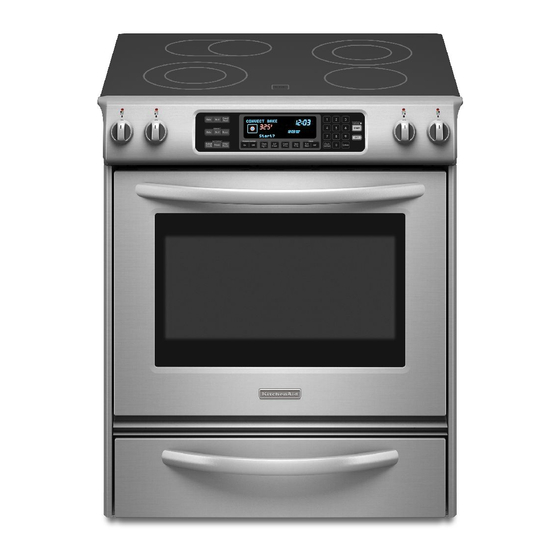
30" (76.2 CM) FREESTANDING
AND SLIDE-IN
ELECTRIC RANGES
INSTRUCTIONS
POUR L'INSTALLATION
DE LA CUISINIERE ELECTRIQUE
AUTOPORTANTE
OU
ENCASTRABLE DE 30" (76,2 CM)
Table of Contents/Table
des matieres .............................................................................
2
iMPORTANT:
Save for local electrical inspector's use.
Installer:
Leave installation instructions with the homeowner.
Homeowner:
Keep installation instructions for future reference.
iMPORTANT
:
,&, c onserver pour consultation par I'inspecteur local des installations electriques.
Inetallateur
: Remettre les instructions d'installation au proprietaire.
Proprietaire
: Conserver les instructions d'installation pour reference ulterieure.
9763461
Advertisement
Table of Contents

Related Manuals for KitchenAid KESS907SBL00


Summary of Contents for KitchenAid KESS907SBL00
- Page 1 Kitchen_kid ® INSTALLATION INSTRUCTIONS 30" (76.2 CM) FREESTANDING AND SLIDE-IN ELECTRIC RANGES INSTRUCTIONS POUR L'INSTALLATION DE LA CUISINIERE ELECTRIQUE AUTOPORTANTE ENCASTRABLE DE 30" (76,2 CM) Table of Contents/Table des matieres ................iMPORTANT: Save for local electrical inspector's use. Installer: Leave installation instructions with the homeowner. Homeowner: Keep installation instructions for future reference.
- Page 2 TABLE OF CONTENTS TABLE DES MATIERES S¢CURIT¢ DE LA CUISINIC:RE ........... RANGE SAFETY ................INSTALLATION REQUIREMENTS ..........EXIGENCES D'INSTALLATION ........... Tools and Parts ................Outillage et pieces ..............Location Requirements ..............Exigences d'emplacement ............Electrical Requirements - U.S.A. Only ......... 7 Specifications de I'installation electrique ........
-
Page 3: Range Safety
RANGE SAFETY Your safety and the safety of others are very important. We have provided many important safety messages in this manual and on your appliance. Always read and obey all safety messages. This is the safety alert symbol. This symbol alerts you to potential hazards that can kill or hurt you and others. All safety messages will follow the safety alert symbol and either the word "DANGER"... -
Page 4: Installation Requirements
IN STALLATION REQUIREMENTS Gather the required tools and parts before starting installation. IMPORTANT: Observe all governing codes and ordinances. Failure to meet codes and ordinances could lead to fire or Read and follow the instructions provided with any tools listed here. - Page 5 Product Dimensions Slide-in Range Freestanding Range D 30" (76.2cm) A. 53/4 ``(14.6 cm) E. 30" (76.2 cm) A. 3011/16 ' ' (77.6 cm) B. 30" (76.2 cm) F. 27_A'' (69.2 cm) max. from B. 35-%" (90.5 cm) height to E. 27¼" (69.2 cm) from handle handle to standoff at back of to standoff at back of underside of cooktop edge...
- Page 6 Installation Clearances Cabinet opening dimensions shown are for 25" (64 cm) countertop depth, 24" (61 cm) base cabinet depth 36" (91.4 cm) countertop height. Freestanding Range Slide-in Range E. For minimum clearance to A. 4" (10.2 cm) rain. clearance A. 4" (10.2 cm) min. clearance F.
-
Page 7: Location Requirements
Ifcodes permit and a separate ground w ire isused, i tis If connecting to a 4-wire system: recommended thataqualified electrical installer determine that This range is manufactured with the ground connected to the theground p athisadequate and wire gauge isinaccordance cabinet. - Page 8 A time-delay fuse or circuit breaker is recommended. This range is equipped with a CSA International Certified ;s{: <_T[/: C /_,@ <-' Power Cord intended to be plugged into a standard 14-50R wall receptacle. Be sure the wall receptacle is within reach of range's final location.
- Page 9 INSTALLATION INSTRUCTIONS 2. Measure from the floor to the underside of the range cooktop. ) _ _ _; __,_ ..Excessive Weight Hazard Use two or more people to move and install range. Failure to do so can result in back or other injury. A.
- Page 10 If range height adjustment is necessary, use a wrench or Contact a qualified floor covering installer for the best procedure pliers to loosen the 4 leveling legs. for drilling mounting holes through your type of floor covering. This may be done with the range on its back or with the range Before moving range, slide range onto shipping base, cardboard or hardboard.
-
Page 11: Installation Instructions
Align anti-tip bracket holes with holes in floor. Fasten anti-tip Making sure the anti-tip bracket is installed: bracket with screws provided. • Look for the anti-tip bracket securely attached to floor. • Slide range back so rear range foot is under anti-tip bracket. - Page 12 Power S upply Cord Direct W ire Electrical Shock Hazard Electrical Shock Hazard Disconnect power before servicing. Disconnect power before servicing. Use 8 gauge copper or 6 gauge alurninum wire. Use a new 40 amp power supply cord. Electrically ground range. Plug into a grounded outlet.
- Page 13 Style 2: Direct wire strain relief 4. Complete installation following instructions for your type of electrical connection: • Remove the knockout as needed for the flexible conduit connection. 4-wire (recommended) • Assemble a UL listed conduit connector in the opening. 3-wire (if 4-wire is not available) Electrical Connection Options If your home has:...
- Page 14 Connect the neutral (center) wire to the center terminal Direct Wire Installation: Copper or Aluminum Wire connector using one of the hex washer head screws. Securely tighten screw for proper electrical connection. This range may be connected directly to the fuse disconnect circuit breaker box.
- Page 15 Connect the bare ground wire to the range using the ground- 3-wire connection: Direct Wire link screw and cup washer. The ground wire must be attached first and must not contact any other terminal. Use this method only if local codes permit connecting ground conductor to neutral supply wire.
-
Page 16: Level Range
For power supply cord-connected ranges: 1. Unplug the power supply cord. 2. Check that anti-tip bracket is installed: 1. Check that all parts are now installed. If there is an extra part, go back through the steps to see which step was skipped. •... - Page 18 SECURITE DE LA CUISINIERE Votre s6curit6 et celle des autres est trbs importante. Nous donnons de nombreux messages de s6curite importants dans ce manuel et sur votre appareil menager. Assurez-vous toujours lire tousles messages de securite et de vous y conformer. Ce symbole d'alerte de securite vous signale les dangers potentiels de deces et de blessures graves a vous et &...
- Page 19 EXIGENCES DqNSTALLATION Rassembler les outils et pieces necessaires avant de commencer IMPORTANT : Observer les dispositions de tousles codes et I'installation. Lire et suivre les instructions fournies avec les outils reglements en vigueur. Le non-respect de ces codes et indiques ici. reglements pourrait entrafner un incendie ou un choc electrique.
- Page 20 Dimensions du produit Cuisini_re autoportante Cuisini_re encastr_e A. 53/4" (!4,6 cm) E. 30" (76,2 cm) A. 3OWed' (77,6 cm) D. 30" (76,2 cm) B. 30" (76,2 cm) F. 27V4" (69,2 cm) : Longueur B. 35%" (90,5 cm) : Hauteur E. 27Y4" (69,2 cm) : Longueur maximale de la poign_e au jusqu'a la pattie inf_rieure de de la poign_e au support 9...
- Page 21 D_gagements de s_paration & respecter Les dimensions de I'espace d'installation entre les placards sont valides pour I'installation entre des placards de 24" (61 cm) avec plan de travail de 25" (64 cm) & hauteur de 36" (91,4 cm). Cuisini_re encastr_e Cuisini_re autoportante E.
- Page 22 On recommande I'emploi de fusibles temporises disjoncteurs. Cette cuisiniere est dotee d'un dispositif de branchement (homologation CSA International) destine a @re branche sur une prise de courant murale standard 14-50R. Veiller ace que la prise de courant murale soit placee a portee de la position de service finale de la cuisiniere.
- Page 23 INSTRUCTIONS DfNSTALLATION 2. Mesurer la distance entre le sol et la partie inferieure de la table de cuisson. Risque du poids excessif Utiliser deux ou plus de personnes pour d6placer et ....<C installer la cuisiniereo Le non-respect de cette instruction peut causer une blessure au dos ou d'autre blessure.
- Page 24 A ___S_e_" __ S __ ed _ d _:_ _ _ _:__[ _,:__'_ _ _ si un ajustement de la hauteur de la cuisiniere est necessaire, Contacter un installateur de rev_tements de sol qualifie au sujet utiliser une cle ou une pince pour desserrer les 4 pieds de des meilleures methodes de pergage des trous de montage nivellement.
- Page 25 Aligner les trous de la bride antibasculement avec les trous Verifier que la bride antibasculement est installee : dans le plancher. Fixer la bride antibasculement avec les vis • Verifier que la bride antibasculement est bien fixee au fournies. plancher. •...
- Page 26 Cuisini_res aliment_es par cordon d'alimentation 1. Debrancher le cordon d'alimentation electrique. 2. S'assurer que la bride antibasculement est installee : 1. Verifier que toutes les pieces ont et6 installees, S'il reste une piece, etudier en detail les etapes du processus d'installation •...
-
Page 28: Anti-Tip Bracket Tem Plate
© 2006. All rights reserved. ® Registered Trademark/TM Trademark of KitchenAid, U,S.A., KitchenAid Canada licensee in Canada Printed in U.S.A. Tous droits r6serv6s. ® Marque d6pos6e/-i-M Marque de commerce de KitchenAid, U.S.A., Emploi licencie par KitchenAid Canada au Canada Imprime aux E.-U.