Table of Contents
Advertisement
INSTALLATIONINSTRUCTIONS
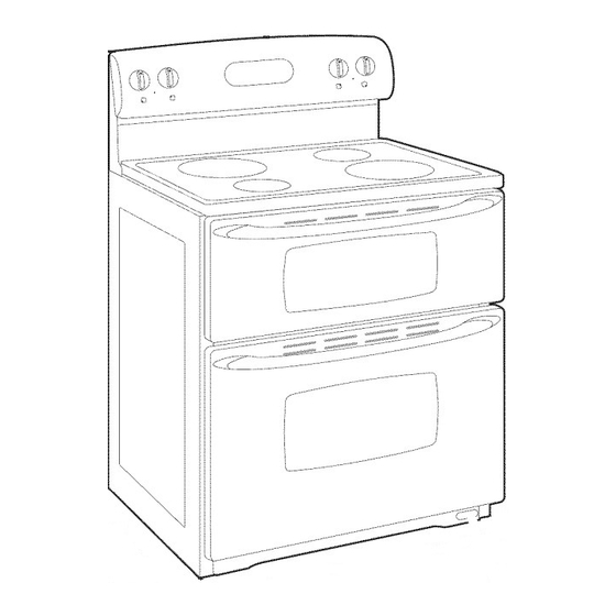
FREESTANDINGELECTRIC RANGE WITH DOUBLEOVENS
Table of Contents
RANGE SAFETY .........................................................................
2
............................................
3
Tools and Parts ........................................................................
3
Location Requirements ...........................................................
3
Electrical Requirements ...........................................................
5
..............................................
6
Unpack Range .........................................................................
6
Adjust Leveling Legs ................................................................
6
Install Anti-Tip Bracket ............................................................
7
Electrical Connection ...............................................................
8
Verify Anti-Tip Bracket Location ............................................
13
Level Range ...........................................................................
14
Complete Installation .............................................................
14
Moving the Range ..................................................................
15
iMPORTANT:
Save for local electrical
inspector's
use.
W10270322A
Advertisement
Table of Contents

Related Manuals for Whirlpool GGE350LWS00


Summary of Contents for Whirlpool GGE350LWS00
-
Page 1: Table Of Contents
INSTALLATIONINSTRUCTIONS FREESTANDINGELECTRIC RANGE WITH DOUBLEOVENS Table of Contents RANGE SAFETY ................. INSTALLATION REQUIREMENTS ..........Tools and Parts ................ Location Requirements ............Electrical Requirements ............INSTALLATION INSTRUCTIONS ..........Unpack Range ................. Adjust Leveling Legs ..............Install Anti-Tip Bracket ............Electrical Connection ............... Verify Anti-Tip Bracket Location .......... -
Page 2: Range Safety
RANGE SAFETY Your safety and the safety of others are very important. We have provided many important safety messages in this manual and on your appliance. Always read and obey all safety messages. This is the safety alert symbol. This symbol alerts you to potential hazards that can kill or hurt you and others. All safety messages will follow the safety alert symbol and either the word "DANGER"... -
Page 3: Installation Requirements
INSTALLATION REQUIREMENTS Gather the required tools and parts before starting installation. IMPORTANT: Observe all governing codes and ordinances. Read and follow the instructions provided with any tools listed • It is the installer's responsibility to comply with installation here. clearances specified on the model/serial number rating label. Tools needed The model/serial number rating label is located on the bottom right front of the toe kick plate. -
Page 4: Installation Instructions
Cabinet Dimensions Product Dimensions Cabinet opening dimensions shown are for 25" (64.0 cm) countertop depth, 24" (61.0 cm) base cabinet depth and 36" (91.4 cm) countertop height. IMPORTANT: If installing a range hood or microwave hood combination above the range, follow the range hood or microwave hood combination installation instructions for dimensional clearances above the cooktop surface. -
Page 5: Electrical Connection
Ifcodes p ermit and a separate ground w ire isused, i tis connecting to a 4-wire system: recommended that a qualified electrical installer determine that This range is manufactured with the ground connected to the the ground path and wire gauge are in accordance with local neutral by a link. - Page 6 INSTALLATIONINSTRUCTIONS Leve Legs _6 '_4 If range height adjustment is necessary, use a wrench or pliers to loosen the 4 leveling legs. This may be done with the range on its back or with the range supported on 2 legs after the range has been placed back to a Excessive Weight Hazard standing position.
- Page 7 Remove the anti-tip bracket that is taped inside the upper Floor Mounting oven with the package containing literature. Determine which mounting method to use: floor or wall. If you have a stone or masonry floor you can use the wall mounting method.
- Page 8 Cc 's secto ' s Direct Wire Power Supply Cord Electrical Shock Hazard Electrical Shock Hazard Disconnect power before servicing. Disconnect power before servicing. Use 8 gauge copper or 6 gauge aluminum wire. Use a new 40 amp power supply cord. Electrically ground range.
-
Page 9: Complete Installation
Style 2: Direct wire strain relief • Assemble a UL listed conduit connector in the opening. • Use Phillips screwdriver to remove screws and slide cord/conduit plate down and out. f ..... • Position cord/conduit plate as shown in the following illustration. - Page 10 Electrical Connection Options Feed the power supply cord through the strain relief in the cord/conduit plate on bottom of range. Allow enough slack to If your home has: And you will be Go to Section: easily attach the wiring to the terminal block. connecting to: 4-wire receptacle A UL listed,...
- Page 11 Securely tighten hex nuts. 3-wire connection: Power Supply Cord NOTE: For power supply cord replacement, only use a power cord rated at 250 volts minimum, 40 amps or 50 amps that is Use this method only if local codes permit connecting chassis marked for use with nominal 13/8 '' (3.5 cm) diameter ground conductor to neutral wire of power supply cord.
- Page 12 Pull the conduit through the strain relief on cord/conduit plate Bare Wire Torque Specifications on bottom of range. Allow enough slack to easily attach wiring Attaching terminal lugs to the terminal block - 20 Ibs-in. (2.3 N-m) to the terminal block. Wire Awg Torque !,?! ...
- Page 13 Bare Wire Torque Specifications 3-wire connection: Direct Wire Attaching terminal lugs to the terminal block - 20 Ibs-in. (2.3 N-m) Wire Awg Torque Use this method only if local codes permit connecting ground conductor to neutral supply wire. 8 gauge copper 25 Ibs-in.
-
Page 14: Level Range
Place oven rack in oven. 1. Check that all parts are now installed. If there is an extra part, go back through the steps to see which step was skipped. Place level on oven rack and check levelness of range, first side to side;... - Page 15 For direct-wired ranges: Electrical Shock Hazard Tip Over Hazard A child or adult can tip the range and be killed. Disconnect power before servicing. Replace all parts and panels before operating. Connect anti=tip bracket to rear range foot. Failure to do so can result in death or electrical shock.
- Page 16 W10270322A 5/09 © 2009. Whirlpool Corporation. Printed in U.S.A. All rights reserved.