
Related Manuals for OpenEye CM-716


Summary of Contents for OpenEye CM-716
- Page 1 2MP Outdoor HD IP Dome Camera User Manual Camera Accessories CM-716 CA-510G CA-510PML CM-716A CA-510W CA-510PMS CM-716I CA-510C CA-510PA25 CM-716AI CA-510P25 CA-510PA50 CA-510P50 www.openeye.net...
- Page 3 The information in this publication is provided “as is” without warranty of any kind. The entire risk arising out of the use of this information remains with recipient. In no event shall OPENEYE be liable for any direct, consequential, incidental, special, punitive, or other damages whatsoever...
-
Page 4: Important Safeguards
Important Safeguards Read Instructions Read all of the safety and operating instructions before using the product. Retain Instructions Save these instructions for future reference. Attachments / Accessories Do not use attachments or accessories unless recommended by the appliance manufacturer as they may cause hazards, damage product and void warranty. Installation Do not place or mount this product in or on an unstable or improperly supported location. - Page 5 Installation and Storage • Install electricity wiring carefully. Please note that input electricity to the unit is at tolerance of DC 12V/AC 24V ± 10%. The camera is capable of surge protection; ensure AC power model unit is grounded appropriately against damage by heavy current or electric shock.
- Page 6 Warning DANGEROUS HIGH VOLTAGES ARE PRESENT INSIDE THE ENCLOSURE. DO NOT OPEN THE CABINET. REFER SERVICING TO QUALIFIED PERSONNEL ONLY. Caution C A U T I O N RISK OF ELECTRIC SHOCK DO NOT OPEN CAUTION: TO REDUCE THE RISK OF ELECTRIC SHOCK, DO NOT REMOVE COVER (OR BACK).
-
Page 7: Table Of Contents
Ethernet Cable Connection ..................14 Ceiling Installation ......................15 4S Electrical Box Installation ..................21 Camera Finder ..................24 OpenEye IP Finder ....................... 24 Finding IP Cameras ....................24 Default Username and Password ................ 24 Changing the Network Type ..................25 Setup &... - Page 8 CM-716 and CM-716I Models ................29 CM-716A and CM-716IA Models ................. 30 System ........................31 System ......................... 31 Security ........................ 32 Admin Password ....................32 Add User ......................33 Delete user ...................... 33 Edit user ......................33 Network ........................ 34 Get IP address automatically (DHCP) .............
- Page 9 Multicast Mode ....................57 Frame Rate Control ....................58 Video Mask......................59 Audio ........................60 Transmission Mode ..................60 Server Gain Setting ..................61 Bit Rate ......................61 Camera ........................62 Exposure ......................62 White Balance ...................... 63 Backlight Setting ....................63 Brightness ......................
-
Page 10: Introduction
Designed for tough environments where standard security cameras are not suited to survive, the CM-716 is equipped with a heater allowing operation in temperatures as low as -31°F (-35°C). The CM-716 camera can be connected to both 24vAC and 12vDC power or to a PoE switch but 24vAC power is required to operate the on-board heater. -
Page 11: Getting Started
Before proceeding, please check that the box contains the items listed here. If any item is missing or has defects, DO NOT install or operate the product and contact your dealer for assistance. CM-716 Camera Power Cable Self Tapping Screws... -
Page 12: Camera Overview
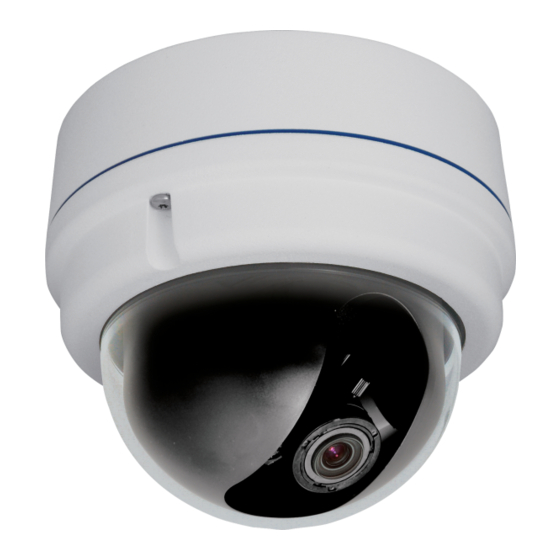
CAMERA OVERVIEW Before installing or connecting the dome camera, please refer to this section and complete preparations for dome setup and all switch settings. Dimensions • Diameter – 151 mm (5.9 inches) • Height – 130 mm (5.12 inches) -
Page 13: Connections
Connections Item Definition Reset Restore Factory Default Settings Analog Video Output Alarm I/O Alarm Input - Alarm Input + Alarm Output - Alarm Output + Audio I/O Output (L) Output (R) Ground Input Power 12vDV / 24vAC Power (+) Power (-) RJ45 10/100 Ethernet PoE 31186AA... -
Page 14: Installation
When using 12vDC or 24vAC power, refer to the pin definition table in the Camera Overview > Connections section for the proper 2-wire connection. Note OpenEye recommends against using more than one power source at a time. Do not use a PoE power source when providing the camera with 12vDC or 24vAC power. -
Page 15: Ceiling Installation
CEILING INSTALLATION The IP Dome Camera can be installed directly on a wall or ceiling. The wall or ceiling must have enough strength to support the IP Dome Camera. Use the supplied Torx tool to unscrew the two Torx screws on the side of the dome cover and remove the dome cover. - Page 16 Unscrew the Torx screw on the camera module, as indicated in the figure, with the supplied Torx tool. Press the sides of the snap-on module, as indicated in the figure, and detach it from the Dome Camera’s housing. Mark the positions of the four screw holes on the base of the Dome Camera at the chosen installation location.
- Page 17 Fasten the camera housing to the ceiling with the supplies screws Thread the power and Ethernet cables through the side conduit entry or the back conduit entry. Note The power cable is omitted if using PoE. 10. Connect the power and Ethernet connectors on the camera with their respective cables.
- Page 18 Note The terminal blocks should face the side conduit entry, as shown in the figure. 12. Use the OpenEye IP Finder software to locate the camera on the network and complete configuration of the camera. 13. After connecting to the camera, adjust the camera's zoom level and focal length using...
- Page 19 14. Adjust the camera to the desired angle. Pan adjustment range is nearly 360°; rotation angle range approaches to 270°. Tilt is adjustable between ﹣10° ~ 90°. Pan Adjustment Tilt Adjustment Note Adjust the lens carefully within the limits mentioned above, or the cables underneath will be damaged.
- Page 20 17. Screw the two Torx screws on the side of the dome cover tightly to fasten the dome cover.
-
Page 21: 4S Electrical Box Installation
4S ELECTRICAL BOX INSTALLATION Before installing the camera in a 4S Electrical Box, unscrew and open the dome cover with the Security Torx. Run the wires (Ethernet and power) through the wall to the 4S box. Note The Power Cable is omitted if using PoE. Press both sides of the Inner Cover and remove it from the Dome Camera. - Page 22 Unscrew the Torx screw on the camera module, as indicated in the figure, with the supplied Torx tool. Press the sides of the snap-on module, as indicated in the figure, and detach it from the Dome Camera’s housing.
- Page 23 Attach the snap-on module to the camera housing, and screw the module screw tightly with the Security Torx to secure the camera module. Use the OpenEye IP Finder software to locate the camera on the network and complete configuration of the camera.
-
Page 24: Camera Finder
OPENEYE IP FINDER Use the included IP Finder software to easily find your network cameras for initial setup. The OpenEye IP Finder software is included on the CD with all OpenEye IP devices. Finding IP Cameras Open the Software CD on the recorder. -
Page 25: Changing The Network Type
Log in to the camera with the appropriate User Name and Password. Note The default User name is Admin and the default Password is1234. The username and password are case sensitive. OpenEye recommends you change the Admin password for security reasons. Resetting the Camera If it is necessary to reset the camera to the factory default settings, hold down the Reset button (see Connections) for 30 seconds. -
Page 26: Connecting A Stream
OpenEye IP cameras using third party software like VLC media player (http://www.videolan.org). To connect the camera you may need to provide the stream URL. All OpenEye IP cameras are capable of delivering two RTSP streams, as well as streaming MJPEG over HTTP. -
Page 27: Connecting Over The Internet
There are some challenges with connecting to OpenEye IP cameras over WAN (internet) connections because the camera streams video over RTSP. RTSP is an excellent protocol for media and is now used on many IP cameras (including OpenEye) as the default streaming option. -
Page 28: Viewer Software
ActiveX controls and plug-in settings. For additional information on adjusting the settings of your Internet Explorer browser contact your system administrator or refer to FAQ #1914 at openeye.net If your internet browser asks for permission to install the ActiveX control, you must allow the ActiveX control to continue the installation. -
Page 29: Home
Logout – Change user. Home CM-716 and CM-716I Models Screen Size Adjustment – Click the screen size buttons to adjust image display size x1/2 and full screen. Digital Zoom Control – In full screen mode, right-click to activate digital zoom and use the scroll wheel to zoom in/out. -
Page 30: Cm-716A And Cm-716Ia Models
CM-716A and CM-716IA Models The CM-716A is equipped with a motorized autofocus lens that makes installation quick and easy. There are six main buttons that are used when setting up the CM-716A: • Zoom Tele • Zoom Wide • Focus Near •... -
Page 31: System
System Note The System tab is only accessible by the Administrator. System Host Name – The Host Name is used to identify the camera on your system. If camera based Motion Detection is enabled and is set to send alarm message by Mail/FTP, the host name entered here will display in the alarm message. -
Page 32: Security
Security Admin Password To change the administrator password, type a new password in the Admin Password box and confirm below. Note The maximum length of the password is 14 characters. The following characters are valid: A-Z, a-z, 0-9, !#$%&’-.@^_~. -
Page 33: Add User
Add User The user name and passwords are limited to 16 characters. There is a maximum of twenty user accounts Type the new User name and Password Select the appropriate check boxes to give the user Camera Control, Talk and Listen permissions. -
Page 34: Network
Every network device has a unique Media Access Control (MAC) address that can be used for identification. The MAC address is located on the bottom of each camera, and on the box label (the OpenEye IP Finder also displays the MAC address for identification). Record your camera’s MAC address for identification in the future. - Page 35 When using static IP address to log in to the IP Camera, you can access it either through OpenEye IP Finder software or type the IP address directly in the Address bar of your internet browser. General • IP address – The IP Address is necessary for network identification.
-
Page 36: Ddns
DDNS DDNS (Dynamic Domain Name Service) is a service that allows a connection to an IP address using a hostname (URL) address instead of a numeric IP address. Most Internet Service Providers use Dynamic IP Addressing that frequently changes the public IP address of your internet connection;... -
Page 37: Mail
Mail The camera can send an e-mail via Simple Mail Transfer Protocol (SMTP) when motion is detected or when the sensor input is activated. SMTP is a protocol for sending e-mail messages between servers. SMTP is a relatively simple, text-based protocol, where one or more recipients of a message are specified and the message text is transferred. -
Page 38: Ftp
The camera can send alarm message to a specific File Transfer Protocol (FTP) site when motion is detected or when the sensor input is activated. You can assign alarm message to up to two FTP sites. Enter the FTP details, which include server, server port, user name, password and remote folder, in the appropriate boxes. -
Page 39: Application
Application The CM-716 is equipped with one alarm input and one relay output to connect to an alarm system to catch event images. Refer to Camera Overview > Connections to connect alarm devices to the IP Camera if needed. Alarm Switch – Enable or disable the alarm function. - Page 40 • Record Stream to SD Card – Select the item and the alarm-triggered recording will be saved to your micro SD card. The pre-trigger buffer recording option allows users to check what happened to trigger the alarm. The pre-trigger buffer time range is from 1 to 3 seconds.
-
Page 41: Motion Detection
Motion Detection Motion Detection allows the camera to detect motion and trigger alarms when motion in the detected area exceeds the determined sensitivity threshold value. In the Motion Detection page, there is a motion detection window (red box) displayed on the Live View Pane. - Page 42 When motion detection is activated, the Motion pop-up window will open. When motion is detected, the signals will be displayed on the Motion window as shown below. Motion Detection Turn motion detection on or off. The default setting is Off. Motion Detection Setting •...
- Page 43 Triggered Action You can specify which actions the camera should take when motion is detected. • Enable Alarm Output – This will activate the camera’s alarm output. • Send Alarm Message by FTP/E-Mail – Select to send an alarm message to a configured FTP server and/or e-mail address when motion is detected.
- Page 44 File Name – Enter a file name in the box, ex. image.jpg. The uploaded image’s file name format can be set in this section. Please select the one that meets your requirements. • Add date/time suffix File name: imageYYMMDD_HHNNSS_XX.jpg Y: Year, M: Month, D: Day H: Hour, N: Minute, S: Second X: Sequence Number •...
-
Page 45: Storage Management
Storage Management The CM-716 has an integrated microSD™ card that can be used to record video or images. The card slot is compatible with a microSD™ card up to 8GB. Device Information – Displays the storage total size and free space information of the included microSD™... -
Page 46: Recording
Recording The recording schedule allows you to set up scheduled recording to the microSD™ card. Recording Schedule – The camera can be set up to record continuously until the card is full (or overwrite old data, see the Storage Management section). The camera can also be set up to record only during a scheduled time. -
Page 47: Snapshot
Snapshot The camera supports a JPEG snapshot function. You can specify a storage location for the snapshot images. The default location is: C:\. Note If you are using Windows Vista or 7, you will need to change the Snapshot location. Windows UAC does not allow internet programs to write directly to C:\ for security reasons. -
Page 48: Information
Information The Information page contains the camera’s System Log, User Information and Parameter List. System Log Click System Log to view the system log file. The content of the file provides useful information about configuration and connections. -
Page 49: View User Information
View User Information The Administrator can view each user’s login information and privileges on the View User Information page. All users for the camera are listed under User information. The example below shows that the Admin password is 1234 and there is one user named User with the password 4321. -
Page 50: Parameters List
Parameters List Click Parameter List to view the system parameter settings. -
Page 51: Software Upgrade
Software Upgrade Upgrading the Camera Viewer Software Note Make sure the new firmware file is available before starting a software upgrade. Click Browse and select the firmware file. Note Do not change the file name, or the system will not be able to update to the new firmware. - Page 52 When the upgrade process is complete the viewer will return to the Home page. After updating it is important to make sure the camera viewer software is updated: Close your browser. Go to the Windows Control Panel and double-click Add or Remove Programs. Locate the Camera Viewer software on the Currently installed programs list, and click Remove to uninstall the previous software version.
-
Page 53: Maintenance
Maintenance On the Maintenance page you can export the cameras current configuration, or import the configuration for a camera. Use the factory default page to reset the IP Camera to factory default settings if necessary. Note Do not import configuration files from different models of cameras. Set Default –To reset the IP camera to the factory default settings, including the default IP address, click Set Default. -
Page 54: Video And Audio Streaming Settings
Video and Audio Streaming Settings On the Streaming tab, you can configure specific video resolution, video compression mode, video protocol and audio transmission mode. Video Format Select the desired video resolution for the camera on the Video Format page. The DVR will record video based on the resolution selected here. -
Page 55: Video Rotate Type
Video Rotate Type You can change the orientation of the video output if necessary. • Normal transmits the image as the camera sees it. • Flip transmits the image upside down and mirrored. • Mirror transmits a mirror image. • 180 degree transmits the image upside down. -
Page 56: Video Compression
Video Compression You can select an MJPEG/H.264 compression mode on the video compression page appropriate for your application. You can also select to display compression information on the Home page. MJPEG compression settings include: • high compression, low bitrate, low quality •... -
Page 57: Video Ocx Protocol
Video OCX Protocol On the Video OCX protocol page, you can select different protocols for streaming media over the network. In the case of multicast networking, you can select the Multicast mode. Video OCX protocol setting options include: • RTP over UDP •... -
Page 58: Frame Rate Control
Frame Rate Control Setting the camera to transmit fewer frames can save bandwidth. Use the Frame Rate Control to adjust the camera’s frame settings if necessary. Each of the MJPEG and H.264 streams can have a separate frame rate setting from 1 to 30 frames per second Note When set to 1920 x 1080, the max frame rate decreases to 15 frames per... -
Page 59: Video Mask
Video Mask You can use the video mask page to define a privacy mask to keep users from viewing parts of the image. You can add two privacy masks and choose a color to obscure the live view from users. Active Mask Function •... -
Page 60: Audio
Audio On the Audio page, the Administrator can select an audio transmission mode and audio bit rate. Note Audio monitoring and recording laws vary from location to location. It is highly recommended that you consult your local, state and federal laws to verify that you are in compliance before implementing audio recording. -
Page 61: Server Gain Setting
Server Gain Setting Set the audio input/output gain levels for sound amplification. The audio gain values range from 1 to 6. Sound can be turned off if audio gain is set to Mute. Bit Rate Selectable audio transmission bit rate include: 16 kbps (G.726) 24 kbps (G.726) 32 kbps (G.726) -
Page 62: Camera
Camera Exposure The exposure is the amount of light received by the image sensor and is determined by the width of lens diaphragm opening (iris adjustment), the amount of exposure by the sensor (shutter speed) and other exposure parameters. Full Auto Mode •... -
Page 63: White Balance
White Balance A camera needs to find reference color temperature, which is a way of measuring the quality of a light source, for calculating all the other colors. The unit for measuring this ratio is in degree Kelvin (K). Users can select one of the White Balance Control modes according to the operating environment. -
Page 64: Contrast
Contrast Correct the contrast of the entire image by adjusting the Contrast level, ranging from -6 ~ +19. Saturation Adjust the saturation of color components in an image through the Saturation function, which is adjustable from -6 ~ +19. Digital Zoom Zoom in to the center of the image. -
Page 65: Specifications
SPECIFICATIONS CAMERA SPECIFICATIONS Model CM-716 CM-716A CM-716I CM-716IA Image Sensor 1/2.7” CMOS IP Rating IP66 Type / Format H.264 / MJPEG Wide Dynamic Range Digital Wide Dynamic Range 0.2 LUX (Color) / 0.02 LUX (B&W) / 0 0.2 LUX (Color) / 0.02 LUX (B&W) -
Page 66: Ir Specifications
IR SPECIFICATIONS Model CM-716 CM-716A CM-716I CM-716IA IR LEDs – 24 IR LEDs (850nm) IR Range – Up to 50 ft (15 m) IP SPECIFICATIONS Model CM-715 CM-715A CM-715I CM-715AI Video Compression H.264 / MJPEG Dual Streaming H.264 + MJPEG, H.264+H.264... -
Page 67: Appendix A
APPENDIX A SET UP INTERNET SECURITY If the installation of ActiveX Control is blocked, you will need to either set the Internet Security Level to the default setting, or change the ActiveX controls and plug-ins setting. Setting Internet Security Level to Default Open Internet Explorer. -
Page 68: Adjusting Activex Controls And Plug-Ins
Adjusting ActiveX Controls and Plug-ins Open Internet Explorer. Click the Tools tab in the menu bar. Click Internet Options. Click Custom Level. The Security Settings window will pop up. Under ActiveX Controls and Plug Ins, set all items to Enable or Prompt. Items may vary according to your version of Internet Explorer. - Page 69 © 2012 OpenEye All rights reserved. No part of this publication may be reproduced by any means without written permission from OpenEye. The information in this publication is believed to be accurate in all respects. However, OpenEye cannot assume responsibility for any consequences resulting from the use thereof.
Need help?
Do you have a question about the CM-716 and is the answer not in the manual?
Questions and answers