Table of Contents
Advertisement
Advertisement
Table of Contents

Related Manuals for Spektrum AR7200BX


Summary of Contents for Spektrum AR7200BX
- Page 1 AR7200BX User Guide...
- Page 2 Age Recommendation: Not for children under 14 years. This is not a toy. WARNING AGAINST COUNTERFEIT PRODUCTS Thank you for purchasing a genuine Spektrum product. Always pur- chase from a Horizon Hobby, Inc. authorized dealer to ensure authentic high-quality Spektrum product. Horizon Hobby, Inc. disclaims all support...
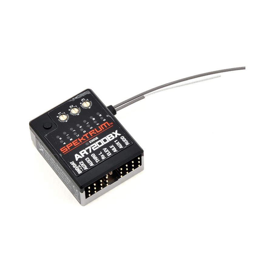
- Page 3 The AR7200BX combines the proven BeastX™ flybarless technology with a Spektrum™ 7-channel, high-speed, 2048 receiver. This combination provides the ultimate in performance and simple installation. The AR7200BX is perfect for mini (up to 450 class) helicopters. Using an optional DSMX remote receiver adds necessary path diversity for even the largest electric, glow, gas and turbine-powered helicopters.The AR7200BX is compatible with all Spektrum...
-
Page 4: Specifications
Swashplate— Swashplate— Direct Cyclic Feed Forward Cyclic Gain Tail Dynamic Setup Button Menu Point Status LED Features • Integrated BeastX flybarless technology and Spektrum 7-channel receiver • Optional DSMX remote receiver capable • SmartSafe™ failsafe system • Flight Log and Telemetry compatible (optional) • 2048 Resolution • High-speed 11ms operation when used with capable transmitters Applications • 250–800 sized nitro, gas and electric flybarless 3D helicopters • Scale flybarless helicopters CAUTIoN: Do not use with flybar helicopters or airplanes. WARNING: For first-time use or when making mechanical changes that involve throw, always ensure you reset the servo limits to prevent binding. -
Page 5: Antenna Polarization
The remote receiver antenna must be at least 2 inches away from the main receiver’s antenna. The AR7200BX is compatible with all DSM2 and DSMX transmitters, even when using the optional DSMX remote receiver. -
Page 6: Receiver Installation
Receiver Installation Attach the AR7200BX receiver using one of the provided gyropads. The AR7200BX must be in a low vibration position, such as the receiver or gyro platform. The mounting platform must be perpendicular to the main shaft. Helicopters usually have enough room on the frame to separate the main feeder antenna and the optional remote receiver. - Page 7 The AR7200BX can be attached flat, upright or inverted under the helicopter. The servo connector pins must always point toward the front or rear of the helicopter. Make sure the edges of the AR7200BX are all parallel with the corresponding axes of the helicopter.
-
Page 8: Setup Procedure
Setup procedure Power on the transmitter first. The AR7200BX initializes when the receiver is powered on. Do not move the AR7200BX or the helicopter while the receiver is initializing. You can lay the helicopter on its side to prevent it from moving in windy conditions. Receiver Initialization Cycle 1. LEDs cycle and then the firmware version will display for 3 seconds. 2. LEDs H through N cycle to initialize the receiver inputs. 3. LEDs A through G cycle to calibrate the sensors. 4. The swashplate moves a small amount and the Status LED turns solid after initialization completes. Status-LED Tail gyro is in Normal-Rate mode... -
Page 9: Exiting The Menu
When LED (N) is solid, quickly press the setup button to exit the menu. The AR7200BX will also automatically exit the menu after 4 minutes of inactivity. The AR7200BX will not automatically exit at points D, G, I and J to allow time for mechanical helicopter adjustments. CAUTIoN: Never fly the helicopter when the AR7200BX is in the Setup or Parameter Menu. -
Page 10: Setup Menu
120Hz Red Solid 165Hz Blue Flashing *=Factory Setting 200Hz Blue Solid Push the setup button to save the selection and move to menu point (C). To see a complete Spektrum servo reference chart, refer to the servo chart on spektrumrc.com. - Page 11 C. Tail Servo Center position/pulse Length Almost all tail servos work with 1520µs (micro seconds). There are a few tail servos available that use a different center position pulse length. Status-LED Tail servo center position pulse length User Defined (requires PC software) 960µs Purple Solid 760µs Red Solid *=Factory...
- Page 12 E. Setting the Tail Servo Endpoints Adjust the limit of the tail rotor blades to achieve the best throw. The best throw is determined by either the maximum possible control travel of the tail slider or the maximum allowed tail rotor blade angle of attack. Make sure the tail rotor blades move in the correct direction (see your helicopter manual for more information).
- Page 13 G. Adjusting the Swashplate Servo Centering Menu point G electronically adjusts the center point of the cyclic servos. 1. With all swashplate servos connected, the servos are now operating in their center position or “reference position”. The Status LED is Off. 2. Install the servo horns on the servos so the horns form an angle close to 90° with the linkage rod.
-
Page 14: Swashplate Mixer
H. Swashplate mixer Select the electronic swashplate mixer required for your helicopter or choose “mechanical” if the helicopter uses a mechanical mixer. The AR7200BX supports 90°, 120° and 140° swashplates. You can also use any swashplate geometry by selecting User Defined (PC software required). Refer to your helicopter manual for more information on CCPM. CAUTIoN: NEVER use your transmitter’ s electronic swashplate mixing. All CCPM mixing is done by the AR7200BX. - Page 15 I. Setting the Swashplate Servo Directions Menu point (I) ensures the swashplate servos are moving correctly. Note that the proper aileron, elevator and collective pitch direction (right/left, up/down) will be corrected later using the servo reversing setting in the transmitter. Try each of the four possible combinations until the swashplate moves correctly.
- Page 16 J. Teaching the Cyclic pitch Geometry CAUTIoN: Do not touch any stick on your transmitter when entering menu point (J). This will cause unwanted flight behavior. 1. Move the rotor blades so that they are parallel to the tail boom. 2.
- Page 17 L. Adjusting the Cyclic Swashplate Limit Menu point (L) adjusts the maximum possible tilting of the swashplate for aileron and elevator. The deflection is limited in a circular path, similar to a cyclic ring function, preventing swashplate binding at full aileron and elevator travel. 1. Carefully move the sticks for aileron, elevator and pitch to all maximum endpoints.
- Page 18 4. If the swashplate changes direction and rotates against the direction of the helicopter, use the rudder stick to change the direction. 5. Push the setup button to save the selection and exit the Setup Menu (N). The setup steps of the AR7200BX are finished. It is now necessary to continue setting up the dials and parameters options. Status-LED...
-
Page 19: Recommended Power System Test Guidelines
This is the #1 cause of power interruptions in electric helicopters. The AR7200BX has a minimum operational voltage of 3.5 volts; it is highly recommended the power system be tested per the following guidelines. Recommended power System Test Guidelines Perform the following test with a voltmeter. The Spektrum Flight Log or Telemetry... -
Page 20: Smartsafe ™ Failsafe
Range Testing Before each flying session, and especially with a new model, perform a range check. All Spektrum aircraft transmitters incorporate a range testing system which, when activated, reduces the output power, allowing a range check. 1. With the model on the ground and the motor/engine off, stand 30 paces (approx. - Page 21 Dials and Tail Gyro Gain To adjust the dials: Only use the original Spektrum AR7200BX adjustment tool to prevent damage to the dials. Dial 1: Swashplate—Cyclic Gain Turn Dial 1 clockwise to increase the swashplate gain. Factory setting for Dial 1 is horizontal (50% swashplate gain). Use the factory setting for your first flights. Typically this setting is ideal for 450 class helicopters. If you are flying larger helicopters it may be necessary to slightly increase the cyclic gain positions.
- Page 22 Status-LED Rate Mode Purple Solid Blue Flashing Heading Lock Mode Blue Solid The color of the Status LED indicates the selected mode when the AR7200BX is ready for operation. When the gain channel is centered, LED A = 0% gain. The maximum adjustable tail gain is 100% in both modes (LED N = 100%). One of the LEDs A–N will light for 10 seconds to show the amount of tail gain. (A) = 0% to (N)=100%. For the first flights, do not use a gain higher than F or G in Heading Lock mode.
-
Page 23: Parameter Menu
100% parameter menu To enter the Parameter Menu: 1. When the AR7200BX is ready for flight, press and hold the setup button until the LED flashes next to menu point (A). 2. Release the setup button. 3. Press the setup button once to move to the next menu point. The Parameter Menu only has 8 menu points (A through H). - Page 24 ImpoRTANT: Unlike digital trims in the transmitter, menu point (A) is not a sepa- rate trim function. If the new center position is saved once in Parameter menu point (A), it will also change the servo center position in Setup menu point (G). once the center position is saved in menu point (A), it is no longer possible to delete the trimming.
- Page 25 Press the setup button once to move to Parameter menu point (D). D. Tail Heading Lock Gain Heading Lock gain determines how constant the tail will maintain the rotation rate from the rudder stick. 1. Start with Heading Lock gain set to low or very low and maximize the tail gain in your transmitter. 2. Increase the Heading Lock gain in the AR7200BX until the desired result are achieved. Heading Lock Gain Too Low Pirouettes are inconsistent in fast forward flight or in crosswind conditions. Heading Lock Gain Too High Fast tail-direction changes are more difficult to control. The tail may also move...
- Page 26 Stick deadband is the range around the very center of the stick where the AR7200BX will not react. Depending on the calibration of the transmitter, the sticks may not be in the exact same center position each time they return to center. This can cause unwanted rotation on the axis of stick movement.
- Page 27 F. Tail—RevomIX The AR7200BX can pre-compensate for torque variations on the tail before any noticeable change. RevoMIX relieves the tail control loop and improves tail performance on helicopters with insufficient tail authority and/or high powered electric helicopters. To see the compensation direction: 1. Move the collective pitch, roll and elevator stick at any time. The tail rotor has to deflect to counter the rotor torque.
- Page 28 G. Cyclic Response Menu point ( G ) adjusts how aggressively the AR7200BX responds to cyclic commands (roll and pitch). Adjusting the cyclic response can reduce the linear control feeling of flybarless systems and make the helicopter response feel more like a flybar helicopter.
- Page 29 Pitch Boost Setting Too High: Can cause the rotor blades to stall when you input fast pitch commands. The collective pitch will feel slow, the opposite of the desired effect. Status-LED Pitch Boost User Defined Off* Purple Solid Red Flashing Medium Red Solid High Blue Flashing...
-
Page 30: The First Flight
The First Flight After powering on the receiver, wait for the AR7200BX to initialize completely (Short movement of swashplate servos and Status LED is Solid Blue or Solid Purple). It is not necessary for the helicopter to be horizontal. Do not move the helicopter at any time during the initialization. You can lay the helicopter on its side to prevent shaking in wind. CAUTIoN: Always complete a control direction test with the transmitter and make sure the sensors are correcting in the proper directions when you tilt, roll and yaw the helicopter by hand. -
Page 31: Version Display
Version Display After the AR7200BX initializes, the Status LED turns Solid Red for 3 seconds. The first two digits of the internal firmware version are displayed. Representation of Values The representation of all values using the menu LEDs is in binary. A lighting menu LED stands for a 1, an off LED for 0. The least significant bits are A and Firmware Version The firmware version consists of three values X, Y, and Z which are displayed for X and Y during the initialization, and for Z if the button is pushed during this initialization. X is displayed though menu LEDs A - G, Y through H - N and Z is using all LEDs A - N. Data Version The data version consists of two values X and Y, which are displayed at the same time through menu LEDs A - G for X and H - N for Y. Hardware Version The hardware version consists of two values X and Y, which are displayed at the same time through menu LEDs A - G for X and H - N for Y. - Page 32 AR7200BX overview SETUP MENU Menu LED solid Blue Blue Status-LED: Purple Flashing Solid Flashing Solid upright flat Mounting orientation (vertical) (horizon- tal)* Swashplate servo User defined 50 Hz* 65 Hz 120 Hz 165 Hz 200 Hz - frequency Tail servo - center User defined 960 μs...
-
Page 33: Year Limited Warranty
1-Year Limited Warranty What this Warranty Covers Horizon Hobby, Inc., (Horizon) warrants to the original purchaser that the product purchased (the “Product”) will be free from defects in materials and workmanship for a period of 1 years from the date of purchase. What is Not Covered This warranty is not transferable and does not cover (i) cosmetic damage, (ii) damage due to acts of God, accident, misuse, abuse, negligence, commercial... - Page 34 have other rights which vary from state to state. Horizon reserves the right to change or modify this warranty at any time without notice. WARRANTY SERVICES Questions, Assistance, and Services Your local hobby store and/or place of purchase cannot provide warranty support or service.
-
Page 35: Warranty And Service Contact Information
Non-Warranty Service Should your service not be covered by warranty service will be completed and payment will be required without notification or estimate of the expense unless the expense exceeds 50% of the retail purchase cost. By submitting the item for service you are agreeing to payment of the service without notification. -
Page 36: Fcc Information
FCC Information This device complies with part 15 of the FCC rules. Operation is subject to the following two conditions: (1) This device may not cause harmful interference, and (2) this device must accept any interference received, including interference that may cause undesired operation. CAUTIoN: Changes or modifications not expressly approved by the party responsible for compliance could void the user’s authority to operate the equipment. This product contains a radio transmitter with wireless technology which has been tested and found to be compliant with the applicable regulations governing a radio transmitter in the 2.400GHz to 2.4835GHz frequency range. -
Page 37: Compliance Information For The European Union
Compliance Information for the European Union Declaration of Conformity (in accordance with ISO/IEC 17050-1) No. HH2011111302 Product(s): AR7200BX 7CH Flybarless Control System Item Number(s): SPMAR7200BX Equipment class: The object of declaration described above is in conformity with the requirements of the specifications listed below, following the provisions of the European R&TTE directive 1999/5/ EN 301 489-1 V1.7.1: 2006 EN 301 489-17 V1.3.2: 2008 Signed for and on behalf of: Horizon Hobby, Inc. - Page 38 © 2011 Horizon Hobby, Inc. DSMX is a trademark of Horizon Hobby, Inc., registered in the U.S. DSM, DSM2, SmartSafe and JR are trademarks or registered trademarks of Horizon Hobby, Inc. The Spektrum trademark is used with permission of Bachmann Industries, Inc. BeastX is a trademark of Markus Schaack and is used with permission. The Spektrum AR7200BX employs technology exclusively licensed to Horizon Hobby, Inc. from freakware GmbH. US 7,391,320. Other patents pending. Created 11/11 32660...
Need help?
Do you have a question about the AR7200BX and is the answer not in the manual?
Questions and answers