Table of Contents
Advertisement
Installation and Operating
instructions
NOTE
TO EQUIPMENT
OWNER:
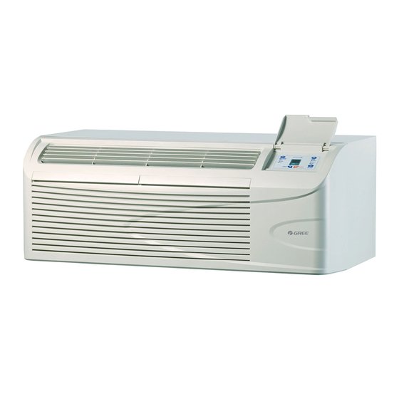
Thank you for purchasing
a Gree PTAC. Please read this Owner's
Information
Manual carefully
before installing
and using this appliance.
Keep this manual for future reference.
For your convenience,
please record the model and serial numbers
of your new equipment
in the
spaces provided. This information,
along with the installation
data and dealer contact information,
will be helpful should your system require maintenance
or service.
UNIT INFORMATION
Model
#
Serial
#
DEALERSHIP
CONTACT
INFORMATION
Company Name:
Address:
INSTALLATION INFORMATION
Date Installed
Phone Number:
Technician Name:
Advertisement
Table of Contents

Related Manuals for Gree PTAC-GAE09AB-D


Summary of Contents for Gree PTAC-GAE09AB-D
- Page 1 Installation and Operating instructions NOTE TO EQUIPMENT OWNER: Thank you for purchasing a Gree PTAC. Please read this Owner's Information Manual carefully before installing and using this appliance. Keep this manual for future reference. For your convenience, please record the model and serial numbers...
-
Page 2: Table Of Contents
.................. 4 - 5 ELECTRICAL DATA .................. INSTALLATION Chassis Installation ................Retrofit Sleeve Preparation ............... Installation of Gree Wall Sleeve Using Non-Gree Grille ..........Install Unit Into Wall Sleeve ..............HOW TO CONNECT .................. SYSTEM CONFIGURATION Ventilation Control ................Adjusting Air Direction ................. -
Page 3: Safety Considerations
READ INSTRUCTIONS BEFORE INSTALLATION OR USE SAFETY CONSIDERATIONS GENERAL Thank you for choosing the Gree PTAC! You can Recognize safety information, This is the safety-alert fee! confident in your selection because of the pride symbol/K When you see this symbo! -
Page 4: Unit Features
UNIT FEATURES . Compressor Protection - To prevent short cycling of the compressor and maximize it's life, there is a random start-up delay minutes compressor and a minimum compressor run time of 3 minutes. . Automatic room freeze protection - automatically will keep the temperature in the room from getting too cold, where water pipes might freeze. -
Page 5: Unit Features
UNIT FEATURES CONTINUED * Unit Configuration - There are many different * Limit Setpoint Range - The unit can be configuration possibilities, through both dipswitches configured to limit the controlling setpoint range. The and the digital keypad, that allow you to configure display will always show the complete setpoint range,... -
Page 6: Electrical Data
ELECTRICAL DATA designed to operate offONE single branch circuits only. NOTE: Use copper conductors only. ELECTRICAL SHOCK HAZARD Table 1--SUGGESTED BRANCH CIRCUIT WIRE SIZES* Failure to follow this warning could result in personal injury or death and/or property damage NAMEPLATE AMPS AWG WIRE SIZEt DO NOT alter cord or plug or use an extension cord. -
Page 7: Installation
(be sure outdoor grille is installed on the sleeve). See Table 3 Manufacturer Wall Sleeve Part Number for details. Gree engineering must approve any other General Electric Metal Sleeve RAB71 retrofit application. Plastic Sleeve RAB77 For competitive retrofit applications,... -
Page 8: Retrofit Sleeve Preparation
Gree sleeve is used with existing non-Gree gri!le. Fig. 6 - Remove Bottom Seal From GE Plastic Sleeve Use of a Gree wall sleeve with a non-Gree grille requires insta!lation of an Accessory Baffle Kit (see Fig. 7), which ensures... -
Page 9: Install Unit Into Wall Sleeve
INSTALL UNIT INTO WALL SLEEVE 1. Carefully remove shipping tape from the front panel and vent door. See Fig. 8. 2. Remove shipping screw from the vent door, if present. See Fig. 9. 3. Remove front panel. See Fig. 10. 4. -
Page 10: How To Connect
Units must be installed using the appropriate 208/230 VOLT power supply kit. See Table 4 - POWER PTAC-GAE07AB-D PTAC-GAA07AB-D CONNECTION CHART. These connections PTAC-GAE09AB-D must be followed. PWRCORD- PWRCORD- PTAC-GAA00AB-D 230V-20A 230V- 15A PTAC-GAE12AB-D 4. Reinstall junction box and cover. PTAC-GAA12AB-D PWRCORD-... -
Page 11: System Configuration
SYSTEM CONFIGURATION VENTILATION CONTROL The ventilation control lever is located at left side of unit, behind front panel. tPu,, ,22 ,obo, NOTE: The vent door shipping hardware must removed before using vent control lever. to operate See figure 9. When set at CLOSE, only the air inside the room is circulated... -
Page 12: Dipswitches
SWITCHES Auxiliary dip switch controls are located behind front panel, through an opening below the control panel. To access, remove front panel. See Fig. 10. switches are accessible without opening control box. Unit must powered Switches effectively change their status. Factory settings for dip... -
Page 13: Keypad Configuration
KEYPAD CONFIGURATION Keypad Configuration Indoor Temperature Displa,L: Allows further configuration of system to desired Change between showing setpoint only on the display application. Changes do not take affect until power is during heating and cooling modes "SP" or displaying cycled on the unit. room temperature during heating and cooling... -
Page 14: Auxiliary Controls
AUXILIARY CONTROLS WALL THERMOSTAT TERMINAL IMPORTANT: Only trained, qualified personnel should access electrical panel on unit and install electrical accessories. Please contact your local electrical contractor, dealer, distributor assistance. Thermostat Wire Routing Fig. 22 - Terminal Connector Removal and Replacement Thermostat wire is field... -
Page 15: Energy Management Input
TERMINAL CONNECTIONS The wall thermostat terminal block is located behind the front panel and is easily accessible on front of control panel. Energy Management (24VAC Common ©R ©w ©Y Note JS LED © © Note TERMINAL BLOCK NOTES: 1. Use terminal "O"... -
Page 16: Operation
OPERATION IMPORTANT: When unit is first started_ high humidity conditions can cause condensation to form discharge grille. Keep doors windows closed. Room humidity will decrease moisture will evaporate. • COOL ® HEAT ,_ FAN Fig. 26 - PTAC CONTROLS ABOUT CONTROLS ON YOUR UNIT... -
Page 17: Care And Cleaning
CARE AND CLEANING FRONT PANEL CASE FILTERS IMPORTANT: TURN UNIT BEFORE Turn unit off and disconnect power supply. CLEANING To clean, use water and a mild detergent. DO NOT use bleach or abrasives. Some commercial cleaners may damage the plastic parts. -
Page 18: Preventative Maintenance
PREVENTATIVE MAINTENANCE Preventative maintenance is essential to proper unit operation, efficiency and longevity. To ensure equipment operates properly, it must be properly maintained. Equipment operation should be checked and verified several times during each year. During regular unit inspection and maintenance, follow guidelines below:... -
Page 19: Troubleshooting
TROUBLESHOOTING POSSIBLE CAUSES SOLUTIONS UNiT DOES NOT START ,' Unit may have become unplugged • Check that plug is plugged securely in wall receptacle. ,' Fuse may have blown Note :Plug has a test/reset button on it. Make sure that the plug •... - Page 20 CONVERSION TABLE R25:20.0kQ (Tolerance 1% ) t[F] Rrnin. [kQ] Rnorn. [kQ] Rrnax. [kQ] 32.0 64.46 65.89 67.34 33.0 62.68 64.03 65.40 34.0 60.95 62.23 63.53 35.0 59.27 60.48 61.71 36.0 57.65 58.80 59.96 37.0 56.07 57.16 58.26 38.0 54.54 55.58 56.62 39.0 53.06...
- Page 21 CONVERSION TABLE (cont.) R25:20.0kQ (Tolerance 1% ) tEF] Rmin.EkQ] Rnom.EkQ] Rmax.EkQ] 97.0 12.30 12.45 12.60 98.0 12.02 12.17 12.32 99.0 11.75 11.90 12.04 100.0 11.48 11.63 11.77 101.0 11.22 11.37 11.51 102.0 10.97 11.11 11.26 103.0 10.72 10.87 11.01 104.0 10.48 10.62 10.77...
- Page 22 >, C] E 37RD > © © "n <<_oz_,_ o°_°__ __ × GA Series - Typical Wiring Schematic far Standard Units...
-
Page 23: Warranty
£ "5 >, >, & ._o _ _< .<< o_w_ .c:: E,-. _ODz _<o i-O._ - ¢)1o & .-_© n<... - Page 24 ¢0 c "¢ .c ¢0 ¢0 © ¢0 >. ,,-: Catalog No. PTAC-GA-2SI Copyright 2010 Gree Electric Appliance Inc. Printed in U.S.A. Edition Date: 09/10 Manufacturer reserves the right to change, at any time, specifications and designs without notice and without...
Need help?
Do you have a question about the PTAC-GAE09AB-D and is the answer not in the manual?
Questions and answers