Table of Contents
Advertisement
Quick Links
User'
User' s s s s s
User'
User'
User'
Manual
Manual
Manual
Manual
Manual
nForce4 4 4 4 4 4X
nForce
nForce
nVIDIA nForce
nVIDIA
nVIDIA
nForce
nVIDIA
nVIDIA
Socket
Socket 754 based Athlon 64
Socket
Socket
Socket
754 based Athlon 64 processor
754 based Athlon 64
754 based Athlon 64
754 based Athlon 64
TRADEMARK
All products and company names are trademarks or registered
trademarks of their respective holders.
These specifications are subject to change without notice.
4X
4X
4X mainboard for AMD
4X
mainboard for AMD
mainboard for AMD
mainboard for AMD
mainboard for AMD
Manual Revision 1.0
April 29, 2005
processor
processor
processor
processor
Advertisement
Table of Contents

Related Manuals for Nvidia nForce4 4X


Summary of Contents for Nvidia nForce4 4X
- Page 1 User’ User’ Manual Manual Manual Manual Manual nForce nForce nForce4 4 4 4 4 4X nVIDIA nVIDIA nForce nVIDIA nForce 4X mainboard for AMD mainboard for AMD mainboard for AMD mainboard for AMD nVIDIA nVIDIA mainboard for AMD Socket Socket...
- Page 2 DISCLAIMER OF WARRANTIES: THERE ARE NO WARRANTIES WHICH EXTEND BEYOND THE DESCRIPTION ON THE FACE OF THE MANUFACTURER LIMITED WARRANTY. THE MANUFACTURER EXPRESSLY EXCLUDES ALL OTHER WARRANTIES, EXPRESS OR IMPLIED, REGARDING ITS PRODUCTS; INCLUDING ANY IMPLIED WARRANTIES OF MERCHANTABILITY, FITNESS FOR A PARTICULAR PURPOSE OR NONINFRINGEMENT.
-
Page 3: Table Of Contents
Table of Contents Page Section 1 Introduction Package Contents ............1- 1 Mainboard Features ........... 1- 2 System Block Diagram ..........1- 5 Section 2 Specification Mainboard Specification ..........2- 1 Section 3 Installatio Mainboard Layout ............. 3- 1 Easy Installation Procedure ........3- 2 CPU Insertion ............. - Page 4 Enable RAID Function ..........5- 4 Section 6 Driver Installation Easy Driver Installation ..........6- 1 Realtek Sound Manager Quick User guide ....6- 2 Appendix Appendix A Update Your System BIOS ......... A- 1 Appendix B NVidia RAID BIOS Utility ..........B- 1...
-
Page 5: Introduction
Introduction Section 1 INTRODUCTION 1-1 Package Contents Optional Items Contents H. Extra USB2.0 port cable A. Mainboard B. User’s manual If you need the optional item, please contact your dealer for assistance. C. Floppy drive cable D. HDD drive cable E. -
Page 6: Mainboard Features
Gigabit Ethernet interface and hardware-optimized Firewall security solution. For more details about the NVIDIA nForce4, please visit the NVIDIA Web site at http://www.nvidia.com. PCI-Express (PCI-E) Next generation peripheral interface to succeed to current PCI bus for the next decade. - Page 7 Introduction S-ATA RAID RAID function available on chipset S-ATA ports. USB2.0 A popular USB standard for plugging in peripherals with up to 480Mbps transfer speed while maintaining backward compatibility with older USB1.1 device. Mainboard is equipped with 6 channel of audio to support Dolby Digital 5.1 audio for DVD-playback.
- Page 8 Introduction Special Features BIOS Features: Magic Health Reports your system hardware status for every boot-up to help detect faults early. Monitor hardware status including CPU temperature, CPU/Memory/ Chipset voltage, fan RPM speed for chassis fan, CPU fan & Power supply fan. EZ-Boot Simply press “ESC”...
-
Page 9: System Block Diagram
Introduction 1-3 System Block Diagram Page 1-5... - Page 10 Introduction Page 1-6...
-
Page 11: Specification
Mainboard Specification Processor Support Socket-754 based AMD Athlon-64/Sempron processor up to 3700+ with 1.6GTs Hyper Transport Chipset nVidia nForce4 4X Chipset Main Memory Two 184-pin DDR SDRAM DIMM sockets Support single-sided or double-sided 2.5v DDR-266/333/400 DIMMs in 128/256/512Mb technologies Supports up to 2GB memory size Expansion Slots Three PCI connectors compliant with PCI v2.3... - Page 12 Specification 10/100Mbps Ethernet from Realtek RTL8201 LAN PHY Audio 6 channel audio from onboard ALC655 AC’97 v2.3 compliant CODEC - Support Aux-In, CD-In - Coaxial S/PDIF-out available on rear panel - Support Jack detection for fool-proof audio device installation - Rear panel audio jacks configuration &...
-
Page 13: Special Features
Specification One Serial port One RJ45 LAN connector Four USB2.0 ports Three Audio jacks Onboard connector and pin-header One floppy drive connector Two ATA-100/133 IDE connector Six extra USB2.0 ports One CD-IN and AUX-IN connector One IR connector Four S-ATA connectors Three Fan connectors Front Panel Controller Supports Reset &... - Page 14 Specification Page 2-4...
-
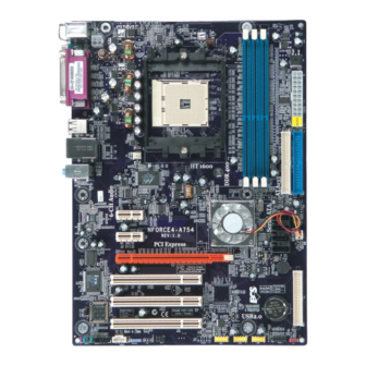
Page 15: Installation
Installation Section 3 INSTALLATION Mainboard Layout Page 3-1... -
Page 16: Easy Installation Procedure
Installation Easy Installation Procedure The following must be completed before powering on your new system: 3-1. CPU Installation 3-2. Jumper Settings 3-3. System Memory 3-4. Expansion Slots 3-5. Device Connectors 3-1 CPU Installation <Figure 2> <Figure 1> Step 1 Step 2 Open the socket by raising the actuation Align pin 1 on the CPU with pin 1 on lever. - Page 17 Installation <Figure 3> <Figure 4> Step 3 Step 4 Close the socket by lowering and Insert the heatsink as shown above. locking the actuation lever. Press the clips in the direction of the arrows shown in Figure 4 to secure the Apply thermal compound to the top of assembly to the CPU socket.
-
Page 18: Jumper Settings
Installation 3-2 Jumper Settings JCMOS: Clear CMOS data Jumper If the CMOS data becomes corrupted or you forgot the supervisor or user password, clear the CMOS data to reconfigure the system back to the default values stored in the ROM BIOS. Settings: 1-2: Normal (Default) 2-3: Clear CMOS... -
Page 19: System Memory Configuration
Installation 3-3 System Memory Configuration Memory Layout The mainboard accommodates two PC2100/PC2700/PC3200 184-pin DIMMs (Dual In- line Memory Modules): • Supports up to 2.0GB of 266/333/400MHz DDR SDRAM. • Supports unbuffered DIMM configurations defined in JEDEC DDR DIMM specification. <Figure 6> DDR DIMM 1 DDR DIMM 2 Memory configurations supported:... -
Page 20: Expansion Slots
Installation 3-4 Expansion Slots PCI-E Slots The mainboard is equipped with two PCI-E*1 compliant with PCI Express 1.0a. PCI-E VGA Slots The elongated PCI-E*16 is intended for PCI-E VGA card installation. PCI-E Slots PCI Slots PCI-E VGA Slot The mainboard is equipped with three PCI Slots PCI slots. -
Page 21: Device Connectors
Installation 3-5 Device Connectors The I/O back panel for this mainboard is shown below. When installing the mainboard into the computer case, use the bundled I/O shield to protect this back panel. RJ45 Parallel Port Line-in/Rear out (Light Blue) PS/2 Mouse Line-out/Front out (Lime) PS/2... - Page 22 Installation Floppy Controller Connector This connects to the floppy disk drive. IDE1/IDE2:Ultra DMA-100/133 Primary/Secondary IDE1 IDE2 IDE Connector This mainboard is equipped with 2 IDE connectors to support up to 4 ATA-100/133 IDE drives. It supports PIO and DMA mode operations for maximum data transfer rate of 133MB/sec per channel.
- Page 23 Installation CFPA: Front Panel Audio Connector When the jumpers are removed this connector can be used for front panel audio. The front panel phone jack should have “normal close” switch. Without phone plug inserted, the rear panel audio is enabled. With phone plug inserted, the rear panel audio will be disabled.
- Page 24 Installation CUSB3/CUSB4/CUSB5: Six USB 2.0 ports This mainboard includes additional USB2.0 ports, identified by 10-pin connector. If you wish to use the additional USB ports, install the card-edge bracket to the system chassis then insert its cables to this 10-pin connector. CUSB3 CUSB5 CUSB4...
- Page 25 Installation CFP: Front Panel Connector HD_LED This LED will light up whenever the hard drive is being accessed. PWR_LED This connects to the power button of the system chassis This switch allows you to reboot without having to power off the system thus prolonging the life of the power supply or system.
-
Page 26: Power-On/Off (Remote)
Installation 3-6 Power-On/Off (Remote) This board has a 24-pin ATX and a 4-pin ATX12V power supply connector to support power supplies with Remote On/Off feature. The 4-pin ATX12V connector must be plugged in for the system to operate safely. The chassis power button should be connected to the mainboard front panel PW_ON header. -
Page 27: Bios Setup
BIOS Section 4 BIOS SETUP Main Menu The ROM BIOS contains a built-in Setup program which allows user to modify the basic system configuration and hardware parameters. The modified data is stored in a battery-backed CMOS, so that data will be retained even when the power is turned off. -
Page 28: Standard Cmos Setup
BIOS The main menu displays all the major selection items. Select the item you need to reconfigure. The selection is made by moving the cursor (press any direction (arrow key ) to the item and pressing the ‘Enter’ key. An on-line help message is displayed at the bottom of the screen as the cursor is moved to various items which provides a better understanding of each function. -
Page 29: Advanced Bios Features
BIOS 4-2 Advanced BIOS Features Selecting the “ADVANCED BIOS FEATURES” option in the CMOS SETUP UTILITY menu allows users to change system related parameters in the displayed menu. This menu shows all of the manufacturer’s default values for the board. Pressing the [F1] key displays a help message for the selected item. - Page 30 BIOS Init Display First This item is used to select whether to initialize the PCI-E or PCI first when the system boots. Options: PCI Slot, PCIEx. Virus Warning During and after system boot up, any attempt to write to the boot sector or partition table of the hard disk drive halts the system and an error message appears.
- Page 31 BIOS Security Option This category allows you to limit access to the System and Setup, or just to Setup. System: The system will not boot and access to Setup will be denied unless the correct password is entered at the prompt. Setup: The system will boot, but access to Setup will be denied unless the correct password is entered at the prompt.
-
Page 32: Advanced Chipset Features
BIOS 4-3 Advanced Chipset Features Choose the “ADVANCED CHIPSET FEATURES” option in the CMOS SETUP UTILITY menu to display following menu. Figure 4: Chipset Features Setup HT Frequency This item allows you select the Hyper Transport Frequency. Options: 1x, 2x, 3x, 4x, 5x. (1x-->200MHz, 2x-->400MHz, 3x-->600MHz, 4x-->800MHz, 5x-->1000MHz) CPU Spread Spectrum This option reduces the EMI (Electromagnetic Interference) generated by the CPU. - Page 33 BIOS DRAM Configuration Scroll to DRAM Configuration and press <Enter>. The following screen appears: 1T/2T Memory Timing For setting DRAM command rate timing. Options: Auto, 1T, 2T. CAS# Latency (Tcl) Enables you to select the CAS latency time. The value is set at the factory depend- ing on the DRAM installed.
- Page 34 BIOS Row cycle time (Trc) This field specifies the Row Cycle Time. RAS# active to RAS# active or auto refresh of the same bank. Options: Auto, 7T ~ 21T. Row refresh cyc time (Trfc) This field specifies the Row Refresh Cycle Time. Auto-refresh active to RAS# or RAS# to auto refresh.
- Page 35 BIOS Max Async Latency Options: Auto, 1ns ~ 15ns. Read Preamble Time Options: Auto, 2.5ns to 9.5ns in 0.5ns increments. IdleCycle Limit Options: Auto, 4, 8, 16, 32, 64, 128, 256. Dynamic IdleCycle Counter Options: Auto, Disabled, Enabled. R/W Queue Bypass Count Options: Auto, 2, 4, 8, 16.
-
Page 36: Integrated Peripherals
4-4 Integrated Peripherals Figure 5: Integrated Peripherals nVidia RAID Boot ROM Set this to enabled to setup RAID for drives connected to nVidia chipset. Options: Enabled, Disabled. nVidia Lan PXE Boot ROM Enables/disable the onboard nVidia Lan PXE Boot ROM for booting from LAN. - Page 37 BIOS Delay For HDD (Secs) This item allows you to set longer time stand by before system Scan HDD at post screen. Some HDD may need a longer stand by time before it can be detected. Options: 0 ~ 15. OnChip IDE Channel 0/1 The mainboard supports two channel of ordinary IDE interface and one channel of serial ATA interface.
-
Page 38: Onboard Device
BIOS Onboard Device Scroll to Onboard Device and press <Enter>. The following screen appears: Onchip USB Enables the USB controller. Options: Disabled, V1.1+V2.0, V1.1. USB Memory Select used memory space to record USB device information Options: Base memory, Shadow memory. USB Mouse Support Enable/Disable support for USB mouse under DOS. -
Page 39: Legacy Devices
BIOS Legacy Devices Scroll to Legacy Devices and press <Enter>. The following screen appears: Onboard FDC Controller Select “Enabled” if you wish to use onboard floppy disk controller (FDC). If you install an external FDC or the system has no floppy drive, select “Disabled “in this field. Options: Enabled, Disabled. -
Page 40: Power Management Setup
BIOS 4-5 Power Management Setup Choose the “POWER MANAGEMENT SETUP” in the CMOS SETUP UTILITY to display the following screen. This menu allows the user to modify the power management parameters and IRQ signals. In general, these parameters should not be changed unless it’s absolutely necessary. -
Page 41: Pnp/Pci/Pci-E Configuration
BIOS WOL (PME#) From Soft-Off When enabled, NV LAN activity awakens the system from soft-off state. Options: Enabled, Disabled. Power-On by Alarm When set to Enable alarm resume, you can set the date (of month) and time (hh:mm: ss), that will awaken a system which has been powered down. Options: Enabled, Disabled. - Page 42 BIOS Resources Controlled By Determines what controls system PNP/PCI/PCI-E resources. The default is Auto (ESCD). Manual: PNP Card’s resources are controlled manually. The “IRQ Resources” field becomes available and you can set which IRQ-X and DMA-X are assigned to PCI/PCI-E and onboard devices. Auto: BIOS assigns the interrupt resource automatically.
-
Page 43: Pc Health Status
BIOS 4-7 PC Health Status Figure 8: PC Health Status Show PC Health in POST When this function is enabled the PC Health information is displayed during the POST (Power On Self Test). Options: Enabled, Disabled. Current CPU/System Temperature Displays the current CPU/system temperature. Current CPU/Power/Chassis FAN Speed Displays the current speed of the CPU, chassis, and power fan speed in RPMs. - Page 44 BIOS +5V, +12V The voltage level of the power supply. 3VSB The voltage level of 3V Standyby. Battery (V) The voltage level of the battery. ACPI Shutdown Temperature This is the temperature that the computer will turn off the power to combat the effects of an overheating system.
- Page 45 BIOS Smart Fan example: Only need to set the items in gray. The system will automatically calculate intermediate temperature Temp LM and Temp MH and the corresponding Duty LM and Duty MH. How effective Smart CPU Fan is will depend on fan design. Most fans have built-in thermistor and may self adjust its speed.
-
Page 46: Power Bios Features
BIOS 4-8 POWER BIOS Features This page lets you adjust various parameters to obtain improved performance for overclocking. Warning: Overclocking requires expert knowledge and risks permanent damage to system components. We recommend you leave these parameters at their default values for proper operation. Figure 9: Frequency/Voltage Control CPU Frequency Enables you to increment the CPU’s clock generator at 1 MHz step. - Page 47 BIOS PCIE Clock Enables you to subtle tune the PCIE frequency at increments of 1MHz step. Options: 100 to 145 in 1MHz increments. AMD K8 Cool’n’Quiet Reduce the noise and heat from you PC when AMD’s Cool’n’Quiet technology is enabled. Options: Enabled, Disabled.
-
Page 48: Defaults Menu
BIOS 4-9 Defaults Menu Selecting “Defaults” from the main menu shows you two options which are de- scribed below Load Fail-Safe Defaults When you press <Enter> on this item you get a confirmation dialog box: Load Fail-Safe Defaults (Y/N) ? N Pressing ‘Y’... -
Page 49: Supervisor/User Password Setting
BIOS 4-10 Supervisor/User Password Setting This function lets you set either Supervisor or User Password, or both, to prevent unauthorized changes to BIOS menus. supervisor password: full rights to enter and change options of the setup menus. user password: only enter but no rights to change options of the setup menus. -
Page 50: Exit Without Saving
BIOS 4-11 Exiting BIOS Save & Exit Setup Pressing <Enter> on this item asks for confirmation: Save to CMOS and EXIT (Y/N)? Y Pressing “Y” stores the selections made in the menus in CMOS – a special section of memory that stays on after you turn your system off. The next time you boot your computer, the BIOS configures your system according to the Setup selections stored in CMOS. -
Page 51: Raid Configuration
RAID Configuration Section 5 RAID CONFIGURATION Introduction This section gives a brief introduction on RAID-related background knowledge and a general procedure to setup RAID system on this mainboard. RAID Basics RAID (Redundant Array of Independent Disks) is a method of combining two or more hard disk drives into one logical unit known as a RAID array. - Page 52 RAID Configuration RAID 0 (Striping) RAID 0 reads and writes sectors of data interleaved between multiple drives. If any disk member fails, it affects the entire array. The disk array data capacity is equal to the number of drive members times the capacity of the smallest member. The striping block size can be set from 4KB to 64KB.
-
Page 53: Nvidia Raid Features
RAID Configuration nVidia RAID Features The nVidia RAID solution uses the nForce4 series chip as a RAID controller, which is a 4-channel S-ATA solution. Listed below are the main features and benefits of nVidia RAID: • Support four S-ATA hard disk drives. -
Page 54: Enable Raid Function
RAID Configuration Enable RAID Function For any RAID controller, the general procedure to enable RAID function are shown below: Note: If you are not installing O/S into the RAID disks, you may skip Step 3 & Step 4. Step 1: Enable RAID ROM The system BIOS may disable all RAID function by default. - Page 55 Step 2: Create RAID Array RAID arrays are created using the RAID controller’s BIOS Boot ROM utility. NVIDIA nForce4 4X Power-on the system and wait for the RAID BIOS Setting utility message on the screen. Press the ”F10” key to enter its BIOS configuration utility.
- Page 56 RAID Configuration 2. A main menu screen will appear (Autorun feature) 3. Select the page “RAID floppy” 4. Insert a blank floppy into the A:drive 5. Click on the required driver to begin copy into the floppy Step 4: Install O/S into RAID disk Proceed to install Windows XP/2000/NT4.0.
-
Page 57: Driver Installation
This item can installs all drivers automatically. Method 2 This item can allows you to install the drivers selectively. Step 1 : Click “nVIDIA nForce Driver” to install chipset driver. Step 2 : Click “USB 2.0 Driver” to install USB 2.0 driver. Step 3 : Click “AC’97 AUDIO Driver”... -
Page 58: Realtek Sound Manager Quick User Guide
Driver Installation Realtek Sound Manager Quick User-guide Introduction To obtain the best performance from your audio system, run the "Sound Manager" utility to adjust the settings to suit your needs. This section of the manual is intended to provide a quick user-guide to setup "Sound Manager". For more detailed information, refer to "Sound Manager manual"... - Page 59 Driver Installation Equalizer: <Figure 3> 3. There are 10 bands of equalizer control, check "ON" when you want to adjust the equalizer. Speaker Configuration: <Figure 4> 4. This page displays the mainboards's phone jack function when a corresponding audio mode (no. of speaker) is selected. Figure 4 above shows the phone jack setup for 2 channel mode.
- Page 60 Driver Installation Speaker Test: <Figure 5> 5. To test the speaker , select the “Speaker Test” page and click directly on the speakers shown on the screen. This board is equipped with Jack Sensing capability. If an audio device is plugged into the wrong connector, a warning message will appear to remind users to check the connection.
- Page 61 Driver Installation Connector Sensing: <Figure 7> 7. EZ-Connection shows the result of the detection. “Audio Connector” column reflects the settings used in the "Speaker Configuration" page. “Current Connection” column shows the type of device detected. If the results do not match, an exclamation mark will appear on the right side. Connector Sensing: <Figure 8>...
- Page 62 Driver Installation HRTF Demo: <Figure 9> 9. This page lets you test the HRTF 3D Positional Audio features. Microphone: <Figure 10> 10. The “Noise Suppression” feature uses software to reduce background delay microphone recording. Page 6-6...
- Page 63 Driver Installation General: <Figure 11> ALC655 11. This page displays information regarding the audio hardware and software. To remove "Sound Manager" icon from Windows Task bar, uncheck "Show icon in system tray". Page 6-7...
- Page 64 Driver Installation Page 6-8...
-
Page 65: Appendix
Appendix Appendix A A-1 Update Your System BIOS Download the xxxxx.EXE file corresponding to your model from our website to an empty directory on your hard disk or floppy. Run the downloaded xxxxx.EXE file and it will self extract. Copy these extracted files to a bootable floppy disk. Note: The floppy disk should contain NO device drivers or other programs. - Page 66 Appendix 5. Key in File Name to save previous BIOS to file. X X X X X X X X X x x x x x . b i n x x x x x . b i n 6. To confirm and proceed, please key in [Y] to start the programming. X X X X X X X X X x x x x x .
-
Page 67: Nvidia Raid Bios Utility
Appendix Appendix B B-1 NVIDIA RAID BIOS Utility Power-on the system and wait for the RAID BIOS Setting utility message on the screen. Press the ”F10” key to enter its BIOS configuration utility. Using the Define a New Array Window If necessary, press the tab key to move from field to field until the appropriate field is highlighted. - Page 68 Appendix To designate a free disk to be used as a RAID array disk, 1) Tab to the Free Disks section. The first disk in the list is selected 2) Move it from the Free Disks block to the Array Disks block by pressing the rightarrow key (->...
- Page 69 Appendix Use the arrow keys to select the array that you want to set up, then press Enter. The Array Detail window appears. The Array Detail window shows information about the array that you selected, such as Striping Block used, RAID Mode, Striping Width, Disk Model Name, and disk capacity.
- Page 70 Appendix...
Need help?
Do you have a question about the nForce4 4X and is the answer not in the manual?
Questions and answers