
Related Manuals for Hafler P7000


Summary of Contents for Hafler P7000
- Page 1 P7000 Installation & Operation ® PROFESSIONAL POWER AMPLIFIER PROFESSIONAL POWER AMPL...
- Page 2 SHOCK HAZARD, DO NOT EXPOSE THIS EQUIPMENT TO RAIN OR MOISTURE. READ INSTRUCTIONS All the safety and operating instructions of your Hafler equipment should be read before power is applied to the equipment. RETAIN OWNER'S MANUAL These safety and operating instructions should be retained for future reference.
- Page 3 E R F O R M A N C E P7000 Power Rating: FTC (20Hz-20kHz, <0.1% THD) 350 wpc into 8 500 wpc into 4 * 1000 wpc into 8 * *Continuous sine wave power limited by current rating of line fuse.
-
Page 4: Table Of Contents
Theory and Operation of trans• nova ... 6 PC Board Layout ... 7 Schematic Diagram ... 8 Parts List ... 10 P7000 Functional Block Diagram ... 12 Circuit Operation ... 13 Amplifier Module Replacement ... 16 Building Custom XCards ... 17 Resistor Chart ... -
Page 5: Introduction
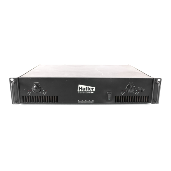
N T R O D U C T I O N The Hafler P7000 is a two channel professional power amplifier suitable for use in any sound reinforcement situation where faithful, accurate reproduction is required. The amplifier uses forced air fan cooling to deliver high power output in a compact size. -
Page 6: Installation
Allow several inches of clearance when mounting these components. AC LINE The P7000 operates from a 120 volt, 60Hz AC power line. Connection is made by 14 gauge, IEC Type 320, grounded line cord. For safety considerations only a properly grounded (earthed) receptacle should be used. -
Page 7: Input Crossover
INPUT CROSSOVER The XCard crossover modules are plug-in cards located inside the amplifier. The P7000 is shipped with 100Hz XCards in each channel. Since each XCard can operate full range, high-pass or low-pass, with a 12dB per octave slope, this allows the amplifier to be used in a wide range of applications. XCards are available for a variety of frequencies from your dealer or through our Customer Service department. -
Page 8: Operation
P E R A T I O N POWER SWITCH The POWER switch is located on the front panel of the amplifier. An internal lamp indicates when it is turned on. Standard practice is to turn the amplifier on last and off first when switching components individually to prevent sending damaging transients, generated in the source components, to the speakers. -
Page 9: Ground Switch
GROUND SWITCH Ground loops are characterized by a hum or buzz through the speakers and are caused by a voltage potential difference between two points in a ground circuit. Ground loops are aggravated when multiple paths exist for a given circuit. Mounting components in a rack with metal rails may introduce ground loops between associated equipment, because the rails can establish an additional ground path. -
Page 10: Technical Reference
FIELD SERVICE CONSIDERATIONS A primary focus during the design and development of the P7000 was to ensure the dependability of the amplifiers. The use of lateral MOSFET output transistors and the low voltage trans•nova input stage combined with careful component selection for the circuit assembly made the reliability goals achievable. - Page 11 P C B O A R D A Y O U T – 7 –...
-
Page 13: Parts List
A R T S I S T DESIGNATOR VALUE ALL RESISTORS IN OHMS 56.2k, 1/4W, 1% 1k, 1/4W, 5% 47k, 1/4W, 5% 47k, 1/4W, 5% 1k, 1/4W, 5% 280, 1/4W, 1% 2.15k, 1/4W, 1% 200 Trim Pot 2.26k, 1/4W, 1% 28k, 1/4W, 1% 300k, 1/4W, 5% 28k, 1/4W, 1%... - Page 14 DESIGNATOR VALUE 10 F, 16V, Electrolytic 10 F, 16V, Electrolytic 0.47 F, 50V 0.47 F, 50V 0.1 F, 50V 0.1 F, 50V 4700 F, 100V, Electrolytic 47 F, 16V, Electrolytic 10 F, 50V, Electrolytic 0.1 F, 50V 0.1 F, 50V 27pF, 50V 0.1 F, 50V 27pF, 50V...
- Page 15 P7000 F UNCTIONAL XCard Crossover Level Control Positive Input Buffer Balanced Signal Negative Input Buffer Crossover XCard LOCK IAGRAM Current Mirror Q104, Q105 R73, CR16 Input Buffer Q17, Q18 CMRR Differential Amp Adjust Q6, Q7 DC Offset Integrator U2B, C22, C21,...
-
Page 16: Circuit Operation
CIRCUIT OPERATION trans•nova Implementation The transistor Q1 is configured to operate as a switch which controls the current source, Q103, of the input differential amp, Q6 and Q7. When Q1 is off the emitter voltage is low turning off Q103. Timing of the Soft Start function is controlled by the charging time of C29 through R13. - Page 17 Fan Speed Regulation Temp TS1, R25 Cooling air for each channel is provided by a DC fan. The fan is configured to track the heatsink temperature, and increases in speed as the amplifier runs hotter. The heatsink temperature, Temp, is determined by the voltage divider TS1 and R25.
- Page 18 Thermal Protection Temp Comparator TS1, R25 The Thermal protection is activated, and shuts down audio operation, when the amplifier heatsink reaches an excessively high temperature. The voltage divider R22 and R23 establishes the reference voltage on pin 5 of U5B. The control voltage, Temp, on pin 4 is established by the voltage divider TS1 and R25.
-
Page 19: Amplifier Module Replacement
AMPLIFIER MODULE REPLACEMENT The amplifier modules have been designed to eliminate the need for a special workplace if a field exchange becomes necessary. All wire connections are made with quick connect terminals so soldering is not necessary. The following tools are needed to disassemble the amplifier: Allen wrench, 9/64 Phillips screwdriver, #1 tip Thin nose pliers... -
Page 20: Building Custom Xcards
BUILDING CUSTOM XCARDS The XCard crossover control modules used in the P7000 are a versatile and inexpensive method for configuring the amplifier for a wide range of system applications. The XCard eliminates the need for an external crossover or expensive plug-in accessories for multiple amp applications. -
Page 21: Resistor Chart
RESISTOR CHART The following charts list the resistor values to use for common crossover frequencies. Butterworth Alignment Q = .707 1% resistors used with 0.047 F capacitors Frequency 20Hz 169k 25Hz 133k 30Hz 110k 35Hz 95.3k 40Hz 84.5k 45Hz 50Hz 68.1k 55Hz 61.9k... -
Page 22: Warranty
I M I T E D A R R A N T Y If you encounter any difficulty or have any question concerning your P7000 Amplifier, please call our Technical Support Department weekdays, 8:00 a.m. to 3:30 p.m., Mountain Standard Time, at 800-743-3526. - Page 23 HAFLER PROFESSIONAL A DIVISION OF ROCKFORD CORPORATION 546 SOUTH ROCKFORD DRIVE TEMPE, ARIZONA 85281 U.S.A. IN U.S.A. (602) 967-3565 IN CANADA, (604) 942-1001 IN EUROPE, FAX (49) 4207-801250 IN JAPAN, FAX (81) 559-79-01265 MAN-0963-B 9/95...
Need help?
Do you have a question about the P7000 and is the answer not in the manual?
Questions and answers