Table of Contents
Advertisement
Advertisement
Table of Contents

Subscribe to Our Youtube Channel
Related Manuals for IP Camera HLV-1WCD


Summary of Contents for IP Camera HLV-1WCD
-
Page 1: User Manual
User Manual VANDALPROOF 3-AXIS IP CAMERA... - Page 2 WARNINGS TO REDUCE THE RISK OF FIRE OR ELECTRIC SHOCK, DO NOT EXPOSE THIS PRODUCT TO RAIN OR MOISTURE. DO NOT INSERT ANY METALLIC OBJECT THROUGH VENTILATION GRILLS. CAUTION CAUTION DO NOT CHANGE THE LENS CAUTION: THIS CAMERA DESIGN IS BASED ON THE INCLUDED LENS.
-
Page 3: Table Of Contents
CONTENT Preface Product Specifications IIII Product Installation Monitor Setting Hardware Installation IP Assignment Install ActiveX control Live Video IP Camera Configuration System Network A/V Setting Event List Network Configuration VIII I/O Configuration VIIII Factory Default Package Contents Micro SD Card Compatibility V1.0_120817... -
Page 4: Ii Preface
°C~50°C with heater(option) • Support iPhone/Android/Mac • Triple Streaming • SDK for Software Integration • Free Bundle 36 ch recording software HLV-1WCD Specifications Hardware ARM Cortex A9 256MB Flash 16MB Image sensor 1 / 2.7” 2Megapixel CMOS sensor Lens Type Vari-focal Lens 3~9mm @F1.8... - Page 5 Built-in 18 IR LED IR Distance-15M Audio G.711(64K) / G.726(24Kbps/32kbps) audio compression Input : External Mic in Output : External Audio out Video Output 1 DI / 1 DO Power over Ethernet Power DC 12V Max: 5.52W(IR On), 4.08W(IR Off) PoE Max: 802.3af, 6.72W(IR On), 5.28W(IR Off) Operating Temperature -10°C ~ 50°C/-30°C~50°C(option)
- Page 6 Recording Trigger Motion Detection, IP check, Network break down (wire only),Schedule, DI Video Format AVI, JPEG Video Playback Delete Files Web browsing requirement Windows 7, 2000, XP, 2003, Microsoft IE 6.0 or above, Chrome, Safari, Firefox Mobile support iOS 4.3 or above, Android 1.6 or above Hardware Suggested Intel Dual Core 2.53G,RAM: 1024MB, Graphic card:...
-
Page 7: Iiii Product Installation
IIII Product Installation Monitor Setting Right-Click on the desktop. Select “ Properties” Change color quality to highest (32bit). -
Page 8: Bi Hardware Installation
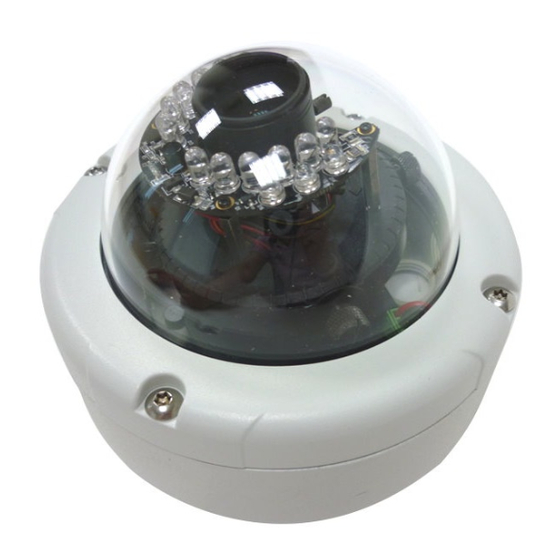
Hardware Installation Connector Instruction Remove the dome cover, and you will see the structure as below. Connect power adaptor, then connect the IP camera to PC or network. Set up the network configurations according to the network environment. About I/ O setting, please refer to chapter VII in User Manual: "I/O Configuration"... - Page 9 We recommend the bottom of housing be set on the smooth flat and closely seal with the surface. When you mount the camera housing on the ceiling or wall, please use the screws with the black rubber o-rings. Without the o-ring, the water may seep into the machine.
- Page 10 Use the 3-Axis bracket to adjust the camera to appropriate angle. Before you close the dome cover, make sure that the black rubber band sticks to the inside of the cover completely. Crook or uneven rubber band may cause the waterproof defective. Lock tightly the screws on the dome cover to ensure there's no gap between the lid and base.
- Page 11 PoE ( Power Over Ethernet)(Optional) 802.3at, 30.0W PoE Switch is recommended Power over Ethernet (PoE) is a technology that integrates power into a standard LAN infrastructure. It enables power to be provided to the network device, such as an IP phone or a network camera, using the same cable as that used for network connection.
-
Page 12: Ci Ip Assignment
IP Assignment You can use the software“IP Installer” to assign the IP address of IP Camera. The software is in the attached CD. There are two language versions of IP installer. Choose one as your need: IPInstallerCht.exe: Chinese version IPInstallerEng.exe: English version There are 3 kinds of IP configuration. - Page 13 IP Installer will search for all IP Cameras connected on Lan. Click “Search Device” to refresh the result list. Click one of the IP Camera listed on the left side. The network configuration of this IP camera shows on the right side. You may change the “name” of the IP Camera as your preference (eg: Office, warehouse).
-
Page 14: Di Install Activex Control
If you link to the IP Camera successgully, there pops a box asking you to log in. Please key in the default user name"admin" and password"admin" when you link to the IP Camera for the first time. You can revise the user name and password later. - Page 15 When popup the following dialogue box, click “Yes”.
-
Page 16: Ivi Live Video
Live Video Start an IE browser, type the IP address of the IP camera in the address field. It will show the following dialogue box. Key-in the user name and password. The default user name and password are “admin” and “admin”. When the IP Camera is connected successfully, it shows the following program interface. - Page 17 Show system time, video resolution, and video refreshing rate Adjust image, 1/2x, 1x, 2x Select video streaming source (If in”Video Setting” the streaming 2 setting is closed, this option will not appear here.) IP Camera supports 2-way audio. Click the “Chatting” check box, then you can use microphone connected to the PC to talk to the Camera side.
-
Page 18: Vi Ip Camera Configuration
IP Camera Configuration Click to get into the administration page as below. Click to back to the live video page. -
Page 19: Ai System
System System Information Server Information: Set up the camera name, select language, and set up the camera time. Server Name: This is the Camera name. This name will show on the IP Installer. (ii) Select language: There are 11 languages to choose from. When you change the language, it will show the following dialogue box for confirmation. - Page 20 Server time setting: Select options to set up time - “NTP”, “Synchronize with PC’s time”, “Manual”, “The date and time remain the same”. Note: To synchronize with the NTP Server, please set the IP camera up on the WAN instead of LAN.
- Page 21 2. User Management IP CAMERA supports three different users, administrator, general user, and anonymous user. Anonymous User Login: Yes: anonymous login is allowed No: Username & password are required to access this IP camera Add user: Type the user name and password, then click “Add/Set”.The guest user can only browse the live video page and is not allowed to enter the configuration page.
- Page 22 System update: To update the firmware online, click “Browse…” to select the firmware. Then click “Upgrade” to proceed. Note: The firmware upgrade might be accompanied by the changing of some setting and function, and the setting options might become different to the user manual that you're reading now.
-
Page 23: Bi Network
Network IP Setting IP Assignment IP Camera supports DHCP and static IP. DHCP: Using DHCP, IP CAMERA will get all the network parameters automatically. (ii) Static IP: Please type in IP address, subnet mask, gateway, and DNS manually. IPv6 Assignment IPv6 is a newer numbering system that provides a much larger address pool than IPv4, which accounts for most of today’s Internet traffic. - Page 24 Port assignment Web Page Port: setup web page connecting port and video transmitting port (Default: 80) (ii) HTTP Port:setup HTTPS connecting port (Default:443) UPnP (Universal Plug and play) This IP camera supports UPnP, If this service is enabled on your computer, the camera will automatically be detected and a new icon will be added to “My Network Places.”...
- Page 25 Windows may ask your confirmation for enabling the components. Click "Yes". • Now you can see the IP devise under the LAN. Double-click the icon to access the camera via web browser. To disable the UPnP, click "Hide icons for networked UPnP devises" in the tasks column.
- Page 26 RTSP setting If you have a media player that supports RTSP protocal, you can use it to receive the video streaming from IP camera. The RTSP address can be set for two streamings respectively. Please jump to Chapter V-C:"Video Setting". There're setting field for RTSP address of two streamings. RTSP Server: enable or disable (ii) RTSP Authentication:...
- Page 27 Multicast, appoint IP Address and port here. TTL means the life time of packet, The larger the value is, the more user can receive the packet. To use Multicast, be sure to enable the function "Force Multicast RTP via RTSP" in your media player. Then key in the RTSP path of your camera: "rtsp://(IP address)/"...
- Page 28 LLTD If your PC supports LLTD, enable this function then you can check the connection status, properties, and device position(like IP address) of this IP Camera in the network map. In the computer running Windows Vista or Windows 7, you can find LLTD through the path: Call out the Control Panel →...
- Page 29 Advanced Https (Hypertext Transfer Protocol Secure): Https can help protect streaming data transmission over the internal on the higher security level. You can select the connection type. "Https" means user cannot connect the camera via Http protocal. The Https path will be: "https://(IP address)/". If you select "Http &...
- Page 30 (iii) There are two ways to set Certificate- Install Signed Certificate or Create Self-Signed Certificate. SNMP(Simple Network Management Protocol) SNMP provides a simple framework for administering networked hardware. To manage the IP camera, you have to prepare a MIB browser or similar tools first.
- Page 31 (ii) SNMPv3: For data security reason, the authentication and encryption assurances are added when developing SNMPv3. The user has to give not only the security name( the same as "community name" in v1&v2c, or sometimes we call it "context name") but the password in order to access the IP camera.
- Page 32 • Cold Start: The camera starts up or reboots. • Setting changed: The SNMP setting is changed. • Network Disconnected: The network connection was broken down. (The camera will send trap messages after the network being connected again) • V3 Authentication Failed: A SNMPv3 user account tries to get authentication but failed.
- Page 33 192.168.50.159 can access. Note: In the list "allow" condition must be ranked before "deny" condition. For example, if we exchange the sequense, set "Deny: 192.168.50.151~192.168.50.161" for the first item and "Allow: 192.168.50.159" for the second item in the list, the IP "192.168.50.159" turns out to be denied by the camera because the "deny"...
- Page 34 IEEE 802.1x IEEE 802.1x is an IEEE standard for port-based Network Access Control. It provides an authentication mechanism to device wishing to attach to a LAN or WLAN. The EAPOL protocol support service identification and optional point to point encryption over the local LAN segment. Please check what version of the authenticator and authentication server support.
- Page 35 PPPoE & DDNS PPPoE: Select “Enabled” to use PPPoE. Key-in Username and password for the ADSL connection. Send mail after dialed: When connect to the internet, it will send a mail to a specific mail account. For the mail setting, please refer to Server settings.
- Page 36 (vi) DDNS Status • Updating: Information update • Idle: Stop service • DDNS registration successful, can now log by http://<username>. ddns.camddns.com: Register successfully. • Update Failed, the name is already registered: The user name has already been used. Please change it. •...
- Page 37 Server setting The settings of Email, FTP and SAMBA are used when the event happens, schedule snapshot executes, or the alarm input is triggered. Select the item to display the detailed configuration options. You can configure either one or all of them. Mail Setting: Set up the server address and account information of your e-mail.
- Page 38 connection. A message box will tell you “OK!” if it works, and a test file will be uploaded to FTP space. In PORT mode, the FTP server builds the connection to the user's data port actively. However, from the user-side firewall's standpoint, the action of connecting from FTP server is often considered to be dangerous and should be blocked.
-
Page 39: Ci A/V Setting
A/V Setting Image Setting For the security and privacy purpose, there are three areas can be setup for privacy mask. Click Area button first and drag an area on the above image, and remember to save your setting. The masked area will not show on both the live view and recording. - Page 40 the level of noise may also increase. Shutter Time: Choose as the location of your camera or fixed shutter time. The shorter the shutter time is, the less light the camera receives and the image becomes darker. Sense-Up: This function increases the sensitivity of camera to get brighter image at night.
- Page 41 Video Setting Video System Setting: Choose the Video System (digital signal) and TV Output (analog signal). b. Basic Mode of Streaming 1 and Streaming 2: Resolution: 1920x1080,1280x720 , 640x480, 320x240, or 176x144 (ii) Profile: Profiles are different compression way of H.264. High profile provides better coding efficiency.
- Page 42 Advanced Mode of Streaming 1 and Streaming 2: Resolution: 1920x1080,1280x720 , 640x480, 320x240, or 176x144 (ii) Profile: High profile provides better coding efficiency. Note that some devises do not support every profile. For example, iPhone4 only supports Main profile. (iii) Bitrate Control Mode: In CBR(Constant Bit Rate) mode, the bitrate keeps consistent all over the video.
- Page 43 better the quality is. (viii) Video Format: H.264 or M-JPEG (ix) RTSP Path: RTSP output connecting route 3GPP Streaming mode: 3GPP Streaming is designed for mobile viewing. Please lower the resolution, bitrate, or frame rate if the image flow isn't smooth when you use the mobile phone.
- Page 44 Audio: IP Camera supports 2-way audio. Audio can be receive by the built-in mic in the IP camera and transmitted to remote PC. User can also send audio from remote PC mic to IP Camera’s external speaker. IP Camera to PC To receive Audio from IP camera, select “Enable”...
-
Page 45: Di Event List
Event List IP Camera provides multiple event settings. Event Setting Motion Detection IP CAMERA allows 3 areas motion detection. When motion is detected, it can send video to some specific mail addresses, trigger the output devise, or save video to remote FTP / Micro SD card / Samba. To set up the motion area, click “Area Setting”. - Page 46 Record File Choose one of the format, AVI or JPEG . Record Time Setting Set up the video recording time for Pre Alarm and Post Alarm when motion is detected, I/O, or other devices is triggered. Note: Pre/Post Alarm record time is base on record time setting and restricted to IP Cam built-in Ram memory.
- Page 47 Schedule Schedule: After complete the schedule setup, the camera data will be recorded according to the schedule setup. Snapshot: After enable the snapshot function, user can select the storage position of snapshot file, the interval time of snapshot and the reserved file name of snapshot.
- Page 48 I/O Setting Input Setting: IP Camera supports input and output. When the input condition is triggered, it can trigger the relay, send the video to mail addresses /FTP server / SAMBA. • Intervel: For example, if you select "10 sec" here, once the motion is detected and action is triggered, it cannot be triggered again within 10 seconds.
- Page 49 Log List Sort by System Logs, Motion Detection Logs and I/O Logs. In addition, System Logs and I/O Logs won’t lose data due to power failure.
- Page 50 SD card Playback Please Insert Micro SD card before use it. Make sure pushing Micro SD card into the slot completely. Click the date listed on this page, and it shows the list of the video. The video format is AVI. Click the video to start Microsoft Media Player to play it.
- Page 51 Copy to PC You can insert the Micro SD card to PC and read the files directly, or use FlashGet instead to download the files from IP camera. (In this way you do not need to pull out Micro SD card from the camera.) To use FlashGet for downloading the image and video data from the Micro SD card, please follow the steps: Enter the data list and right-click "Files link daily", select "save target...
- Page 52 (iv) Click OK to start download. • FlashGet is a free software that can be downloaded from FlashGet official website. The example above is based on FlashGet ver.1.9.6.
-
Page 53: Vii Network Configuration
Network Configuration • Configuration 1: Internet Access: ADSL or Cable Modem IP address: One real IP or one dynamic IP Only IP Camera connects to the internet For fixed real IP, set up the IP into IP Camera. For dynamic IP, start PPPoE. •... - Page 54 • Configuration 3: Internet Access: ADSL or Cable Modem IP address: one real IP or one dynamic IP IP Camera and PC connect to the internet Device needed: IP sharing Use virtual IP, set up port forwarding in IP sharing.
-
Page 55: Viii I/O Configuration
VIII I/O Configuration I/O Connection Please connect the GND & DO pin to the external relay (buzzer) device. Please connect the GND & DI pin to the external trigger device. I/O PIN definition • GND (Ground): Initial state is LOW •... - Page 56 "Relay Out" bottom on the live video page to test if DO / Relay Out works. OnOff Switch mode: Click "ON", the camera will trigger the external output devise for 10 seconds. For example, your alarm buzzer will continuously ring for 10 seconds.
-
Page 57: Viiii Factory Default
VIIII Factory Default If you forget your password, please follow the steps to revert back to default value. • Remove the power and ethernet cable. Press and hold the button as the picture below. • Connect power to the camera again, and do not release the button during the system booting. -
Page 58: Ixi Package Contents
Package Contents IP Camera Adaptor Quick Installation Guide Hex Wrench Star Wrench Screws x4 O-ring x4 Wall Plug x4 • Adaptor: AC100-240V DC12V/1A • The CD includes User manual and software tools. -
Page 59: Xi Micro Sd Card Compatibility
Micro SD Card Compatibility The following is the Micro SD Card recommended: Transcend SDHC class4 16GB SDHC class4 32GB class4 16GB class4 32GB SDHC class6 SDHC class6 SDHC class6 16GB class6 class6 class6 16GB SDHC class10 4GB SDHC class10 8GB SDHC class10 16GB SanDisk...
Need help?
Do you have a question about the HLV-1WCD and is the answer not in the manual?
Questions and answers