
Related Manuals for Thermal Dynamics CutMaster 100


Summary of Contents for Thermal Dynamics CutMaster 100
- Page 1 Plasma Cutting Power Supply CutMaster™ 100 A-02991 Operating Manual March 22, 2004 Manual No. 0-2859...
- Page 3 While the information contained in this Manual represents the Manufacturer's best judgement, the Manufacturer assumes no liability for its use. Plasma Cutting Power Supply CutMaster™ 100 Operating Manual Number 0-2859 Published by: Thermal Dynamics Corporation 82 Benning Street West Lebanon, New Hampshire, USA 03784 (603) 298-5711 www.thermal-dynamics.com Copyright 2001 by Thermal Dynamics Corporation All rights reserved.
-
Page 4: Table Of Contents
TABLE OF CONTENTS SECTION 1: GENERAL INFORMATION ....................1-1 1.01 Notes, Cautions and Warnings ..............1-1 1.02 Important Safety Precautions ............... 1-1 1.03 Publications ....................1-2 1.07 Declaration of Conformity ................1-4 1.08 Statement of Warranty .................. 1-5 SECTION 2: INTRODUCTION ....................... - Page 5 TABLE OF CONTENTS (continued) SECTION 6: PARTS LISTS ........................6-1 6.01 Introduction ....................6-1 6.02 Ordering Information ..................6-1 6.03 Power Supply Replacement ................6-2 6.04 Replacement Parts ..................6-2 6.05 Options and Accessories ................6-2 APPENDIX 1: INPUT WIRING REQUIREMENTS ..............A-1 APPENDIX 2: SEQUENCE OF OPERATION (BLOCK DIAGRAM) ...........
-
Page 7: General Information
SECTION 1: GASES AND FUMES GENERAL INFORMATION Gases and fumes produced during the plasma cutting process can be dangerous and hazardous to your health. 1.01 Notes, Cautions and Warnings • Keep all fumes and gases from the breathing area. Throughout this manual, notes, cautions, and warnings Keep your head out of the welding fume plume. -
Page 8: Publications
• Wear dry gloves and clothing. Insulate yourself from the work piece or other parts of the welding PLASMA ARC RAYS circuit. • Repair or replace all worn or damaged parts. Plasma Arc Rays can injure your eyes and burn your skin. •... - Page 9 6. ANSI Standard Z49.2, FIRE PREVENTION IN THE USE OF CUTTING AND WELDING PROCESSES, obtain- able from American National Standards Institute, 1430 Broadway, New York, NY 10018 7. AWS Standard A6.0, WELDING AND CUTTING CON- TAINERS WHICH HAVE HELD COMBUSTIBLES, ob- tainable from American Welding Society, 550 N.W.
-
Page 10: Declaration Of Conformity
Rigorous testing is incorporated into the manufacturing process to ensure the manufactured product meets or exceeds all design specifications. Thermal Dynamics has been manufacturing products for more than 30 years, and will continue to achieve excellence in our area of manufacture. -
Page 11: Statement Of Warranty
None Warranty repairs or replacement claims under this limited warranty must be submitted by an authorized Thermal Dynamics® repair facility within thirty (30) days of the repair. No transportation costs of any kind will be paid under this warranty. Transportation charges to send products to an authorized warranty repair facility shall be the responsibility of the customer. - Page 12 GENERAL INFORMATION January 27, 2004...
-
Page 13: Introduction
(AC) is low or the DC voltage is higher 2.01 Scope of Manual than shown in the chart. CutMaster 100, 208/230-Volt and 460-Volt Duty Cycle: This manual contains descriptions, operating instructions and basic maintenance procedures for the Thermal Dy-... -
Page 14: Power Supply Options And Accessories
6. Overall Dimensions (including handles) • Length: 27.5 inches (696 mm) • Width: 12.4 inches (315 mm) • Height: 17.3 inches (439 mm) 7. Gas Regulator/Filter Assembly Specifications • Operating Pressure (Output): 70 psi (4.8 bar) • Maximum input gas pressure: 125 psi (8.6 bar) •... -
Page 15: Installation Procedures
SECTION 3: 3.03 Unpacking INSTALLATION The product is packaged and protected to prevent dam- age during shipping. PROCEDURES 1. Unpack each item and remove any packing material. 2. Locate the packing list(s) and use the list(s) to iden- 3.01 Introduction tify and account for each item. -
Page 16: Primary Input Power Connections
4. Pass a customer-supplied, three-conductor input 3.05 Primary Input Power power cable through the access opening in the Connections back panel of the power supply. Refer to Appen- dix 1 for power cable specifications. Tighten the Check the power source for correct voltage before con- strain relief to secure the power cable. -
Page 17: Gas Connections
B. 208/230-Volt Power Supply C. Connecting Gas to Power Supply This power supply includes a factory-installed input The gas supply is connected to the Regulator/Filter As- power cable and plug. sembly located on the rear of the unit. The connection is the same for compressed air or high pressure gas cylin- 1. - Page 18 b. Connect the two stage filter outlet hose to the inlet port of the Regulator/Filter Assembly. c. Use customer-supplied fittings to connect the gas line to the Filter. A 1/4 NPT to 1/4" hose Regulator/Filter Inlet Port barbed fitting is shown as an example. Assembly Bowl Regulator Inlet Port...
-
Page 19: Torch Connections
5. Connect the Negative/Plasma Lead to the bulk- 3.07 Torch Connections head connection inside the Power Supply. NOTE Equipment ordered as a system will have the Torch Note: Actual Bulkhead factory connected to the Power Supply. configuration may differ from that shown. The instructions for connecting the Torch Leads to the Adapter Power Supply are different depending on the type of... - Page 20 B. Machine Systems (Unshielded Leads) 1. Remove the Cover of the Power Supply for access Adapter Negative/Plasma to the Torch Bulkhead Panel. See Section 5.05. Connector Lead Connection 2. Remove the strain relief nut from the Strain Relief. Power Supply Adapter Control Circuit Remote Connectors...
- Page 21 C. Machine Systems (Shielded Leads) 1. Remove the Strain Relief Nut from the Strain Re- Adapter Connector lief. Negative/Plasma Adapter Lead Connection (Supplied With Power Supply) Torch Leads Assembly Control (PIP) Circuit Strain Relief Connectors Shield Connectors Pilot Lead Stud A-02826 Pilot Lead Strain Relief...
-
Page 22: Ground Connections For Mechanized Applications
6 - 8 ft (1.8 - 2.4 m) into the earth so that the For Thermal Dynamics components it is recommended rod contacts moist soil over most of its length. Depend- to use a minimum of 10 AWG (European 6 mm... - Page 23 To test for a proper earth ground, refer to the following D. Routing Of Torch Leads diagram. Ideally, the reading on the multimeter should 1. To minimize RF interference, position torch leads as be as follows: far as possible from any CNC components, drive mo- •...
- Page 24 INSTALLATION PROCEDURES 3-10 Manual 0-2859...
-
Page 25: Operation
B. Control Panel Features SECTION 4: OPERATION 4.01 Introduction This section describes the power supply operating con- trols and procedures, identifies the front and rear com- ponents, and describes the operating procedures. 4.02 Product Features A. General Features 1. Control Panel A-02989 All operator controls, except gas pressure adjustment, Operating Controls and Indicators... -
Page 26: Preparations For Operating
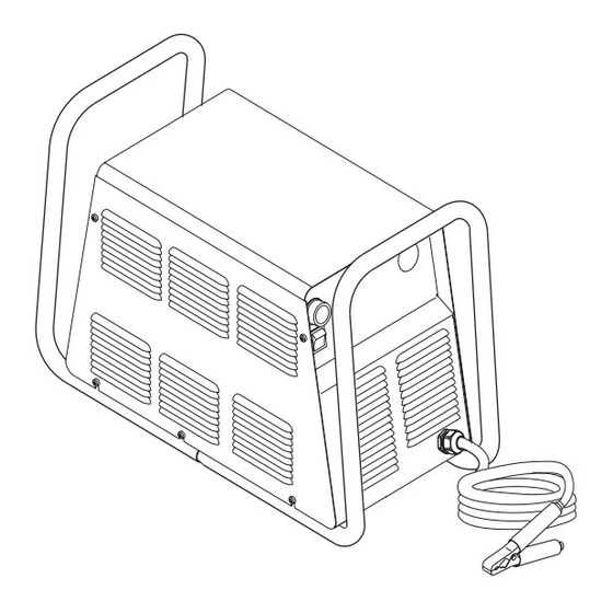
C. Rear Panel Features A. Torch Parts Selection 1. Gas Input Port Check the torch for proper assembly and appropriate front end torch parts. The torch parts must correspond Input connection for compressed air. with the type of operation (cutting or gouging). Re- fer to the torch manual for proper parts selection. -
Page 27: Sequence Of Operation
H. Set Operating Pressure After gas pre-flow: a. Power Supply enabled. DC indicator turns Place the RUN/SET switch to the SET (down) posi- tion. Gas will flow. Adjust gas pressure to 70 psi (4.8 bar). Pilot arc is established. Prepare to Cut Move Torch within transfer distance of workpiece. - Page 28 OPERATION Manual 0-2859...
-
Page 29: Customer & Operator Service
The filter element and spool, with the baffle ring in SECTION 5: place (teeth facing downward) can be screwed back CUSTOMER & OPERATOR into the Regulator body by compressing the spring on the spool. Tighten firmly by hand. SERVICE 5.01 Introduction This section describes basic maintenance procedures per- formable by operating personnel. -
Page 30: Common Faults
Shut off air supply and bleed down system. d. Worn torch parts e. Cutting current too low WARNING Non-Genuine Thermal Dynamics parts used Always turn off the air supply and bleed the system before disassembling the Filter Assembly as injury could result. -
Page 31: Basic Troubleshooting Guide
Improper cutting current C. Common Symptoms e. Non-Genuine Thermal Dynamics parts used A. AC Power indicator 4. Short Torch Parts Life 1. Switch at customer's main power panel in OFF posi- tion. - Page 32 3. Unit is overheated F. Limited output with no control a. Allow unit to cool down for at least 5 minutes. 1. Poor input or output connections Make sure the unit has not been operated be- a. Check all input and output connections. yond Duty Cycle limit.
-
Page 33: Power Supply Basic Parts Replacement
2. Gas supply pressure too high 5.05 Power Supply Basic Parts Replacement a. Maximum 125 psi (8.6 bar) inlet pressure 3. Shield Cup not properly installed. a. Check to see that Control Circuit (PIP) pins are WARNING installed. Refer to the torch manual for details. 4. - Page 34 Loosen, but do not remove, the lower screws, then carefully pull the Cover up and away from the unit to gain access to the inside of the unit. Reinstall the cover as follows: a. Reconnect the ground wire, if necessary. b.
-
Page 35: Parts Lists
SECTION 6: PARTS LISTS 6.01 Introduction A. Parts List Breakdown The parts list provide a breakdown of all replaceable com- ponents. The parts lists are arranged as follows: Section 6.03 Complete Power Supply Replacement Section 6.04 Replacement Parts Section 6.05 Options and Accessories NOTE Parts listed without item numbers are not shown, but may be ordered by the catalog number shown. -
Page 36: Power Supply Replacement
The following items are included with the replacement power supply: work cable & clamp, gas pressure regulator/ filter, and operating manual. Description Catalog # CutMaster 100 Power Supply 208/230VAC, Single-Phase, 60Hz, with input power cable and plug 3-1250-1 400VAC, Three-Phase, 50/60 Hz, with input power cable... -
Page 37: Appendix 1: Input Wiring Requirements
APPENDIX 1: INPUT WIRING REQUIREMENTS Input Power Input Current Input Suggested Sizes (See Notes) Voltage Freq. 1-Ph 3-Ph 1-Ph 3-Ph Fuse (Amps) Wire (AWG) Wire (Canada) (Volts) (Hz) (kVA) (kVA) (Amps) (Amps) 1-Ph 3-Ph 1-Ph 3-Ph 1-Ph 3-Ph 14.4 15.6 15.5 50/60 13.9... -
Page 38: Appendix 2: Sequence Of Operation (Block Diagram
APPENDIX 2: SEQUENCE OF OPERATION (BLOCK DIAGRAM) ACTION ACTION ACTION ACTION ON/OFF switch Close external RUN/SET RUN/SET switch to ON. disconnect switch. switch to RUN. to SET. RESULT RESULT RESULT RESULT AC indicator blinks for 8 Power to system. Gas flow stops. Gas solenoid open, seconds then steady on. -
Page 39: Appendix 3: Torch Control Cable Wiring Diagram
APPENDIX 3: TORCH CONTROL CABLE WIRING DIAGRAM This diagram applies to mechanized systems only. Torch Control Cable Control Connector Plug with Connectors Torch Control Connectors Control Shield Connector Torch Lead Lead Shield A-02801 Assembly Connectors only on Connector Shielded Leads Mate &... -
Page 40: Appendix 4: Maintenance Schedule
APPENDIX 4: MAINTENANCE SCHEDULE This schedule applies to all types of non-liquid cooled plasma cutting systems. Some systems will not have all the parts listed and those checks need not be performed. NOTE The actual frequency of maintenance may need to be adjusted according to the operating environment. Daily Operational Checks or Every Six Cutting Hours: 1. - Page 41 Notes: Manual 0-2859 APPENDIX...
-
Page 42: Appendix 5: System Schematic, 208/230 Volt Units
APPENDIX 5: SYSTEM SCHEMATIC, 208/230 VOLT UNITS INPUT DIODE IGBT PCB ASSEMBLY 19X1756 ASSEMBLY 19X1755 E12A E17A GATE 208/230V COPPER DRIVE STRAP SINGLE PHASE INPUT (78) GATE DRIVE (33) E19A E21A INRUSH +12VDC CHASSIS IGBT PCB ASSEMBLY 19X1756 E12B FILTERING +18V E17B GATE... - Page 43 INDUSTRIAL PARK No. 2 Scale Supersedes WEST LEBANON, NH 03784 603-298-5711 Date: Information Proprietary to THERMAL DYNAMICS CORPORATION. Tuesday, May 15, 2001 Not For Release, Reproduction, or Distribution without Written Consent. Drawn: References NOTE: Unless Otherwise Specified, Resistors are in Ohms 1/4W 5%.
-
Page 44: Appendix 6: System Schematic, 400 And 460 V Units
APPENDIX 6: SYSTEM SCHEMATIC, 400 and 460 V UNITS INPUT DIODE IGBT PCB ASSEMBLY 19X1756 ASSEMBLY 19X1811 E 1 2 A E 1 7 A GATE DRIVE 460VAC 3 PHASE INPUT 460VAC GATE 1 PHASE DRIVE INPUT E 1 9 A E 2 1 A INRUSH + 1 2 VD C... - Page 45 R e v R e vi s ions D a te P C B N o : THERMAL DYNAMICS 1 9 X 1 7 5 3 A s s y N o : E C O 3 7E2 H AS...
-
Page 46: Appendix 7: System Schematic, 600 Volt Units
APPENDIX 7: SYSTEM SCHEMATIC, 600 VOLT UNITS INPUT DIODE IGBT PCB ASSEMBLY 19X1815 ASSEMBLY 19X1811 E 1 2 A E 1 7 A GATE DRIVE 600VAC 3 PHASE INPUT GATE DRIVE E 1 9 A E 2 1 A INRUSH + 1 2 VD C IGBT PCB ASSEMBLY 19X1815 CHASSIS... - Page 47 MAIN CONTACTOR R e v R e vi s ions D a te P C B N o : THERMAL DYNAMICS E C O 1 00032 G C W 0 4 /16/02 A s s y N o : I N D USTRIAL PARK No. 2...
Need help?
Do you have a question about the CutMaster 100 and is the answer not in the manual?
Questions and answers