Table of Contents
Advertisement
Advertisement
Table of Contents

Related Manuals for SoundCraft K1


Summary of Contents for SoundCraft K1
- Page 1 SOUNDCRAFT USER GUIDE...
- Page 2 Information in this manual is subject to change without notice and does not represent a commitment on the part of the vendor. Soundcraft Electronics Ltd. shall not be liable for any loss or damage whatsoever arising from the use of information or any error contained in this manual.
-
Page 3: Table Of Contents
Contents 1. Introduction System Overview Warranty 2. Installation Dimensions Precautions and Safety Instructions Mains Installation General Wiring Procedures Connections 3. Block Diagrams 4. Functional Description Mono Input Channel Stereo Input Channel Group/Matrix Section Master Section 5. Specifications... -
Page 5: Introduction
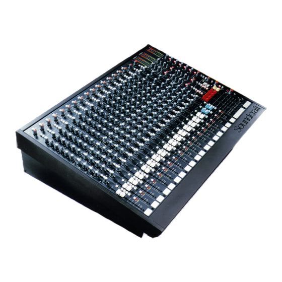
1. Introduction System Overview Warranty Introduction December 1994... - Page 6 Introduction The K is a professional, compact, four-bus sound reinforcement console designed for a wide range of applications in installed and portable sound systems. The console is available in a range of free-standing frame sizes or the smallest frame can be rack-mounted with the optional mounting brackets. The modular construction, with input modules in blocks of four, provides ease of servicing and configuration to suit individual applications.
-
Page 7: Warranty
Equipment has been properly installed in accordance with instructions contained in Soundcraft’s manual; and b) the End User has notified Soundcraft or the Dealer within 14 days of the defect appearing; and c) no persons other than authorised representatives of Soundcraft or the Dealer have effected any replacement of parts maintenance adjustments or repairs to the Equipment;... - Page 8 December 1994 Introduction...
-
Page 9: Installation
2. Installation Dimensions Precautions & Safety Instructions Mains Installation General Wiring Procedures Connections Installation December 1994... -
Page 10: Dimensions
Dimensions 196.80mm DIMENSION ’X’ (7.75") 47.50mm 96.30mm (1.87") Console Dimension ’X’ (3.79") 8 ch. 460.00mm (18.11") 16 ch. 678.53mm (26.71") 24 ch. 920.73mm (36.25") -
Page 11: Precautions And Safety Instructions
Precautions and Safety Instructions General Precautions Avoid storing or using the mixing console in conditions of excessive heat or cold, or in positions where it is likely to be subject to vibration, dust or moisture. Do not use any liquids to clean the fascia of the unit: a soft dry brush is ideal. Use only water or ethyl alcohol to clean the trim and scribble strips. -
Page 12: Mains Installation
Mains Installation Before switching on the K console, check that the mains voltage selector on the power supply unit is set to the correct mains voltage for your area and that the fuse is of the correct rating, this is clearly marked on the power supply. -
Page 13: General Wiring Procedures
To take full advantage of the excellent signal to noise ratio and low distortion of Soundcraft consoles care must be taken to ensure that incorrect installation and wiring does not degrade the performance of the desk. Hum, buzz, instability and Radio Frequency interference can usually be traced to earth loops and inferior earthing systems. - Page 14 Audio Wiring Having provided all equipment with power and earthing connections, consideration must be given to the method of providing audio interconnection and adequate screening of those interconnections. This must be done in a logical sequence to avoid problems and assist in the localisation of problem equipment. Connect the Monitor system to the console and check for any hum, buzz, or RFI.
- Page 15 It is important to remember that all equipment which is connected to the mains is a potential source of hum and interference and may radiate both electrostatic or electromagnetic radiation. In addition, the mains will also act as a carrier for many forms of RF interference generated by electric motors, air–conditioning units, thyristor light dimmers etc.
-
Page 16: Connections
Connections Wiring conventions The K uses two different types of audio connector: 3-pin XLR and " 3-pole jacks. This section describes how to connect external equipment to the console. Correctly-made cables of the proper type will ensure peak performance from your mixer. -
Page 17: Block Diagrams
Block Diagrams Mono Input Stereo Input Master Section Block Diagrams December 1994... - Page 18 Mono Input Module December 1994 Block Diagrams...
- Page 19 Stereo Input Module Block Diagrams December 1994...
- Page 20 Master Section December 1994 Block Diagrams...
-
Page 21: Functional Description
4. Functional Descriptions Mono Input Module Stereo Input Module Matrix/Master Section Functional Descriptions December 1994... -
Page 22: Mono Input Channel
Mono Input Channel The mono input is provided with XLR and jack connectors, either of which may be used for any level of input signal. Normally the XLR signal is used, but inserting a jack automatically disconnects the XLR socket, and applies the jack signal to the input. - Page 23 Internal links are fitted which enable send pots 2 and 4 to be disconnected from their respective PRE switches, and linked independently to the pre- or post-fade signals. Routing The PAN control determines the position of the signal within the stereo image. In the centre position there is a 4.5dB level drop.
- Page 24 Rear Connectors INPUT (3 pin female XLR) Pin 1 Ground Pin 2 Signal Hot Pin 3 Signal Cold JACK INPUT (1/4" TSR Jack) Signal Hot Ring Signal Cold Sleeve Ground INSERT SEND/RETURN, (1/4" TSR Jack) Return signal Ring Send signal Sleeve Ground DIRECT OUTPUT (1/4"...
-
Page 25: Stereo Input Channel
Stereo Input Channel The SENS (Sensitivity) control adjusts the sensitivity of A or B inputs from +14 to -16dBu. Pressing B switches the input source from line A to line B, both of which are electronically balanced, from 1/4" Jack inputs on the rear panel. The left and right jacks of both A and B inputs are normalised together via the switch contacts of the right jack so that a mono signal, plugged into the left jack only, is fed equally to left and right. - Page 26 Routing The BAL (Balance) control determines the relative levels of the L and R signals. In the centre position its gain is unity. Turning it fully clockwise increases the right signal by 4.5dB, and reduces the left signal to zero. Full anticlockwise rotation has the opposite effect.
- Page 27 Rear Connectors LINE A and B, LEFT and RIGHT (1/4" TSR Jacks) Signal Hot Ring Signal Cold Sleeve Ground Functional Descriptions December 1994...
-
Page 28: Group/Matrix Section
Group/Matrix Section Group Output The Group FADER controls the level of the Group signal fed to the Insert Send, with unity gain at the top of the fader. The insert point is pre-fade, and uses an unbalanced send and return at a nominal level of -2dBu. -
Page 29: Master Section
Master Section The master section contains the controls for the main stereo and mono outputs, auxiliary outputs, control room/phones outputs, two-track inputs and talkback input. Main Stereo Outputs The Stereo Mix Left and Right signals are controlled by the L/R FADER. Unity gain is at the top of the fader. - Page 30 A solo system of pre-fade (inputs) and post-fade (outputs) feeds the monitor and phones outputs. Normally, all active AFL & PFL signals are summed together and fed to the monitor and phones outputs. The PFL/AFL LED illuminates to show that a PFL/AFL is active. This overrides the Stereo Mix or 2-Track signal which is normally fed to the monitor/phones output (see below).
- Page 31 PFL Output A ground compensated output is provided for the PFL/AFL signal. This is via a 1/4" jack socket on the rear panel. Rear Connectors MIX/MONO/GRP OUTPUTS (3-pin male XLR) Pin 1 Ground Pin 2 Signal Hot Pin 3 Signal Cold MIX/GRP INSERT SEND/RETURN (1/4"...
- Page 32 4.12 December 1994 Functional Descriptions...
-
Page 33: Specifications
Specifications Specifications December 1994... -
Page 34: Frequency Response
Specifications Frequency Response Any input to any output 20Hz - 20kHz, +0/-0.5dB Total Harmonic Distortion (All measurements at +20dBu) Line In to Group or Mix out Less than 0.01% @ 1kHz Less than 0.025% @ 10kHz Noise (22Hz-22kHz bandwidth, unweighted) Mic Input Equivalent Input Noise Less than -127.5dBu (200ohm source)
Need help?
Do you have a question about the K1 and is the answer not in the manual?
Questions and answers