
Related Manuals for Grizzly G0715P


Summary of Contents for Grizzly G0715P
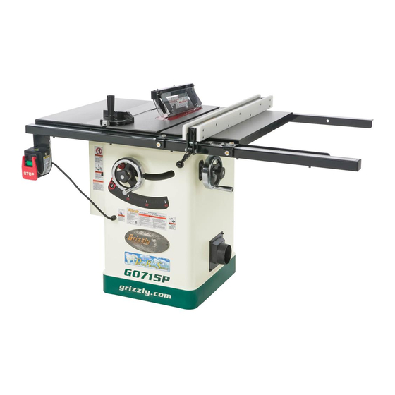
- Page 1 MODEL G0715P POLAR BEAR SERIES ® 10" HYBRID TABLE SAW w/RIVING KNIFE OWNER'S MANUAL WARNING: NO PORTION OF THIS MANUAL MAY BE REPRODUCED IN ANY SHAPE OR FORM WITHOUT THE WRITTEN APPROVAL OF GRIZZLY INDUSTRIAL, INC.
- Page 2 This manual provides critical safety instructions on the proper setup, operation, maintenance, and service of this machine/tool. Save this document, refer to it often, and use it to instruct other operators. Failure to read, understand and follow the instructions in this manual may result in fire or serious personal injury—including amputation, electrocution, or death.
-
Page 3: Table Of Contents
SECTION 4: OPERATIONS ... 27 Table of Contents SECTION ACCESSORIES ... 46 SECTION 6: AFTERMARKET ACCESSORIES FROM GRIZZLY ... 54 SECTION 7: MAINTENANCE ... 57 SECTION 8: SERVICE ... 59 SECTION 9: WIRING ... 72 SECTION 10: PARTS ... 75 WARRANTY AND RETURNS ... -
Page 4: Introduction
INTRODUCTION Manual Accuracy Contact Info your machine may not exactly match the manual Machine Description www.grizzly.com... - Page 5 Use saw-blade guard and spreader for every operation for which it can be used, including all through sawing. c) Keep hands out of the line of saw blade. d) Use a push-stick when required. e) Pay particular attention to instructions on reducing risk of kickback.
- Page 6 Customer Service #: (570) 546-9663 · To Order Call: (800) 523-4777 · Fax #: (800) 438-5901 Weight... 393 lbs. Width (side-to-side) x Depth (front-to-back) x Height... 60 x 36 x 40 in. Footprint (Length x Width)... 20 x 21-1/2 in. Type...
- Page 7 Maximum Blade Diameter... 10 in. Riving Knife/Spreader Thickness... 0.1 in. (2.5mm) Required Blade Body Thickness... 0.071 – 0.094 in. (1.8-2.4mm) Required Blade Kerf Thickness... 0.102 – 0.126 in. (2.6-3.2mm) Maximum Width of Dado... 13/16 in. Blade Tilt... Left 0-45 deg. Arbor Size...
- Page 8 Camlock T-shaped fence with HDPE face Easy glide fence system Powder coated paint Quick-release riving knife and blade guard assembly Includes standard and dado table inserts Device on blade guard allows enabling or disabling of anti-kickback pawls Includes 10" x 40T saw blade...
-
Page 9: Section 1: Safety
SECTION 1: SAFETY For Your Own Safety, Read Instruction Manual Before Operating this Machine The purpose of safety symbols is to attract your attention to possible hazardous conditions. This manual uses a series of symbols and signal words intended to convey the level of impor- tance of the safety messages. - Page 10 DISCONNECTING POWER SUPPLY. APPROVED OPERATION. DANGEROUS ENVIRONMENTS. ONLY USE AS INTENDED. USE RECOMMENDED ACCESSORIES. CHILDREN & BYSTANDERS. REMOVE ADJUSTING TOOLS. SECURING WORKPIECE. FEED DIRECTION. FORCING MACHINERY. GUARDS & COVERS. NEVER STAND ON MACHINE. STABLE MACHINE. AWKWARD POSITIONS. UNATTENDED OPERATION. MAINTAIN WITH CARE. CHECK DAMAGED PARTS.
-
Page 11: Additional Safety For Table Saws
Additional Safety for Table Saws HAND POSITIONING. BLADE GUARD. RIVING KNIFE. KICKBACK. FEEDING WORKPIECE. FENCE. PUSH STICKS/BLOCKS. CUT-OFF PIECES. BLADE ADJUSTMENTS. CHANGING BLADES. DAMAGED SAW BLADES. DADO AND RABBET OPERATIONS. CUTTING CORRECT MATERIAL. -
Page 12: Protecting Yourself From Kickback
Here are some ways to pro- tect yourself if kickback DOES occur: Statistics show that most common acci- dents among table saw users can be linked to kickback. Kickback is typically defined as the high-speed expulsion of stock from the table saw toward its operator. -
Page 13: Glossary Of Terms
Glossary of Terms Arbor: Bevel Edge Cut: Blade Guard Assembly: Crosscut: Dado Blade: Dado Cut: Page 38 Featherboard: Page 46 Kerf: Kickback: VERY Non-Through Cut: Page 28 Parallel: Page 38 Perpendicular: Page 32 Push Stick: Page 49 Page 37 Rabbet: Page 41 Page 38 Rip Cut:... -
Page 14: Section 2: Power Supply
SECTION 2: POWER SUPPLY Availability Electrocution, equipment damage may occur if machine is not correctly grounded and connected to the power supply. Full-Load Current Rating Full-Load Current Rating at 220V ... 8 Amps Full-Load Current Rating at 110V ... 16 Amps Circuit Information For your own safety and protection of property, consult a qualified electrician if... -
Page 15: Grounding Requirements
Grounding Requirements For 220V operation: GROUNDED 6-20 RECEPTACLE 6-20 PLUG Figure 2. For 110V operation: GROUNDED 5-20 RECEPTACLE 5-20 PLUG Figure 3. Serious injury could occur if you connect the machine to power before completing the setup process. DO NOT connect to power until instructed later in this manual. -
Page 16: Voltage Conversion
Converting G0715P to 110V Figure 4 Figure 4. Figure 5 Step 2 Figure 5. -
Page 17: Section 3: Setup
SECTION 3: SETUP This machine presents serious injury hazards to untrained users. Read through this entire manu- al to become familiar with the controls and opera- tions before starting the machine! Wear safety glasses dur- ing the entire setup pro- cess! This machine and its com- ponents are very heavy. -
Page 18: Hardware Recognition Chart
Hardware Recognition Chart... - Page 19 Inventory Note: If you can't find an item on this list, check the mounting location on the machine or examine the packaging materials carefully. Occasionally we pre-install certain components for shipping purposes. Box Contents: (Figures 7–9) Hardware (Not Shown) Figure 7. Figure 8.
- Page 20 Components Hardware and Tools (Not Shown) Figure 10.
- Page 21 Cleanup Before cleaning, gather the following: Basic steps for removing rust preventative: Steps 2–3 Gasoline or products with low flash points can explode or cause fire if used to clean machin- ery. Avoid cleaning with these products. Many cleaning solvents are toxic if concentrat- ed amounts are inhaled.
-
Page 22: Site Considerations
Site Considerations Weight Load Machine Data Sheet Space Allocation See below for required space allocation. Children or untrained people may be seriously injured by this machine. Only install in an access restricted location. Physical Environment Electrical Installation Lighting Figure 11. - Page 23 Assembly To assemble the table saw: Figure 12. Figure 13 Figure 13. Lubrication Page 58 Figure 12 Figure 14. Figure 15. Figure 14 Step 5 Figure 15...
- Page 24 Figure 16 Figure 16. Note: After reinstalling wings, remove all excess masking tape with a razor blade. Figure 17. Figure 18 Figure 18. Figure 19 Figure Figure 19. Step 10...
- Page 25 Figure 20 Figure 20. Installation Page 31. Figure 21. Note: Make sure the cam foot contacts the cam on the fence lock handle before you place the fence on the rail; otherwise, the fence will not lock onto the rail tube. Note: It is permissible for the back of the fence to pivot outward not more than being parallel with the miter slot.
-
Page 26: Power Connection
Figure 23 Figure 23. Figure 24. Power Connection To connect to the power supply: Page Figure 24 Page 12... -
Page 27: Dust Collection
Dust Collection DO NOT operate the Model G0715P without an adequate dust collection system. This saw creates substantial amounts of wood dust while operating. Failure to use a dust collection system can result in short and long-term respiratory illness. Components and Hardware Needed:... -
Page 28: Recommended Adjustments
Test Run Troubleshooting Page 59 To test run the machine: Connection Page 24 Figure 26. Power Recommended Adjustments SECTION 7: SERVICE Adjustments that should be verified: Figure Page 61 Page 63 Page 66... -
Page 29: Section 4: Operations
"how to" books before beginning any projects. Regardless of the content in this section, Grizzly Industrial will not be held liable for accidents caused by lack of training. Operation Overview this... -
Page 30: Basic Controls
Basic Controls START/STOP Switch: Figure 27 Blade Tilt: Figure 28 Figure 28. Blade Height Fence Lock: Non-Through & Through Cuts Non-Through Cuts Figure 29. " Through Cuts Figure Figure 30. Figure... -
Page 31: Workpiece Inspection
Workpiece Inspection Before cutting, inspect all workpieces for the following: Material Type: Foreign Objects: Large/Loose Knots: Wet or “Green” Stock: Excessive Warping: Minor Warping: Blade Requirements Blade Size Requirements: Blade Selection Ripping Blade Features: Figure 31. -
Page 32: Dado Blades
Crosscut blade features: Figure 32. Combination blade features: Figure 33. Laminate blade features: Figure 34. Thin Kerf Blade: Blade Requirements Dado Blades Stacked Dado Blade (see below): Wobble Dado Blade: Figure 35. -
Page 33: Blade Installation
Blade Installation To install the blade: Before proceeding with the next step, wear gloves to protect your hands while handling and installing the blade. Figure 36. Note: The arbor nut has right hand threads; turn it counterclockwise to loosen. Figures 37. Figure 37. -
Page 34: Blade Guard Assembly
Blade Guard Assembly Figure 38 Figure 38. Guard Spreader In order to work properly, the spreader cannot be bent or misaligned with the blade. If the spreader gets accidentally bent, take the time to straighten it or just replace it. Using a bent or misaligned spreader will increase the risk of kickback! Refer to Page 66 to check or adjust alignment if... -
Page 35: Anti-Kickback Pawls
Figure 40. Figure 41 Figure 41. Figure 40. Anti-Kickback Pawls Figure 42 " Page Figure... - Page 36 Disabling Pawls We do not recommend disabling the pawls during normal operations unless absolutely necessary. In most situations, disabling the pawls will increase your risk of serious per- sonal injury in the event of a kickback. The pawls are sharp and can lacerate fingers or hands.
-
Page 37: Riving Knife
Riving Knife Figure 44 Figure 44. Figure 45 Figure 45 To ensure that the riving knife works safe- ly, it MUST be aligned with and correctly adjusted to the blade. Refer to Page 66 to check or adjust the riving knife alignment. How to Install the Riving Knife Guard Page 32... - Page 38 Page 10 Figure 46. Turn OFF the saw and allow the blade to come to a complete stop before removing the cut-off piece. Failure to follow this warn- ing could result in serious personal injury.
-
Page 39: Miter Cuts
Crosscutting To make a crosscut using the miter gauge: Figure 47. Turn OFF the saw and allow the blade to come to a complete stop before removing the cut-off piece. Failure to follow this warn- ing could result in serious personal injury... -
Page 40: Dado Cutting
Blade Tilt/Bevel Cuts Page 61 Figure 49 Figure 49 Dado Cutting Figure Dado Blade Figure 50. DO NOT make through cuts with a dado blade. Dado blades are only intended for non-through cuts. Failure to heed this warning could result in serious injury. Installing a Dado Blade Dado blades have a higher risk of kickback than normal blades because their larger size... -
Page 41: Cutting Dadoes With A Dado Blade
Cutting Dadoes with a Dado Blade Dado blades have a higher risk of kickback than normal blades because their larger size applies stronger forces to the workpiece. This risk increases relative to the depth and width of the cut. To minimize your risk of serious personal injury, ensure that stock is flat and straight, and make multiple light cuts (rather than one deep cut) to achieve... -
Page 42: Cutting Dadoes With A Standard Blade
Cutting Dadoes with a Standard Blade Page 29 To use a standard saw blade to cut dadoes: Page 37 Figure 52 Blade Cut 1 Figure 52. Cut 2 Figure 53. Page Cuts 3+ Figure 54. Figure Blade Figure 54... -
Page 43: Cutting Rabbets With A Dado Blade
ALWAYS replace the blade guard after dadoing is complete. Cutting Rabbets with a Dado Blade Figure Figure 56 Figure 56. -
Page 44: Cutting Rabbets With A Standard Blade
Workpieces that are too tall to properly support with the fence can easily shift dur- ing operation and cause kickback. Instead, place the stock flat on the saw and perform the rabbet cut with a dado blade, as instruct- ed on Page 41. - Page 45 Be certain that stock is flat and straight. Failure to follow these warnings could result in serious personal injury. Note: To determine the maximum resawing height for this table saw, find the maximum blade height, ⁄ ". then double it and subtract...
-
Page 46: Auxiliary Fence
Auxiliary Fence Components Needed for the Auxiliary Fence: Only use furniture-grade plywood, kiln dried hardwood, or HDPE plastic to prevent warping. Tools Needed for the Auxiliary Fence: To build the auxiliary fence: Step 1 Figure 60 Figure 60. Resawing Operations Components Needed for Resawing: You may experience kickback during this procedure. - Page 47 Always use push sticks or push paddles to increase safety and control during opera- tions which require that the blade guard and spreader must be removed from the saw. ALWAYS replace the blade guard after resawing is complete. Figure 62. Steps 7–9...
-
Page 48: Section 5: Shop Made Safety Accessories
We recommend using a bandsaw for making fingers in the next step because it tends to be safer. A table saw can be used, but it will over-cut the underside of the ends, produce a thicker kerf, and require you to stop the blade half-way through the cut, which can be dangerous. - Page 49 Figure 64 Figure 64. Figure 65 Tip: Consider making the miter bar longer for larger featherboards—approximately half the length of the total featherboard—to support the force applied to the featherboard during use. Figure 65. Figure 66. Note: The routed slot, countersink hole, and the flat head screw are essential for the miter bar to clamp into the miter slot.
- Page 50 Mounting Featherboards w/Clamps Figure 67 Figure 67. Figure 67 Step 5 Mounting Featherboard in Miter Slot Figure 68 Figure 68. Step 4 Note: The featherboard should be placed firmly enough against the workpiece to keep it against the fence but not so tight that it is difficult to feed the workpiece.
-
Page 51: Push Sticks
Push Sticks Using a Push Stick Feeding: Figure Making a Push Stick MATERIAL: ⁄ " Grid Figure 71 Supporting: Figure Push Stick Prohibition Zone Supporting Feeding Figure 69. Figure 70. SIZING: SANDING:... -
Page 52: Push Blocks
Push Blocks Push Stick Prohibition Using a Push Block Zone Supporting Figure Feeding Figure 73. CAUTION: Making a Push Block Figure 72 CAUTION: ⁄ " Grid Figure 74... -
Page 53: Narrow-Rip Auxiliary Fence & Push Block
Narrow-Rip Auxiliary Fence & Push Block Material Needed for Narrow Rip Auxiliary Fence & Push Block Material Needed for Push Block Making a Narrow-Rip Push Block for an Auxiliary Fence Figure 75. Note: We recommend cutting the hardwood board oversize, then jointing and planing it to the correct size to make sure the board is square and flat. -
Page 54: Using The Auxiliary Fence And Push Block
Figure 78 Figure 79. Figure 80 Figure 80 Turn OFF the saw and allow the blade to come to a complete stop before removing the cut-off piece. Failure to follow this warn- ing could result in serious personal injury. -
Page 55: Crosscut Sled
Outfeed & Support Crosscut Sled Tables Figure 82 Figure 81 Figure 82. Figure 81. -
Page 56: Section 6: Aftermarket Accessories From Grizzly
To minimize this risk, only install accessories recommended for this machine by Grizzly. NOTICE Refer to the newest copy of the Grizzly Catalog for other accessories available for this machine. G7314Z—Heavy-Duty Base Figure 83. - Page 57 H8875—26" Wide Outfeed Roller System Model G1317 Shown Figure 86. T10222—Router Table Attachment T10223—Sliding Table Attachment T10223 Figure 87. Forrest Woodworker II Saw Blades T20778—10", 20 Teeth T20779—10", 40 Teeth T23527—10", 48 Teeth T10222 Figure 88. Forrest Dado Blades H4756— 8", 24 Teeth, 1/4"–29/32" Groove T23267—8", 24 Teeth, 3/16"–1/4"...
- Page 58 12 oz Spray ® G2871—Boeshield T-9 12 oz Spray G2870—Boeshield ® T-9 4 oz Spray ® H3788—G96 Gun Treatment 12 oz Spray ® H3789—G96 Gun Treatment 4.5 oz Spray Figure 91. H7583—Grizzly Tenoning Jig Figure 92 H3309— Featherboard Figure 93.
-
Page 59: Section 7: Maintenance
SECTION 7: MAINTENANCE To prevent serious per- sonal injury from shock or accidental startup, always disconnect power from machine doing any maintenance. Schedule Daily (Ongoing) Weekly Monthly Page 71 Every 6–12 Months Page 58 Page 58 Cleaning before Unpainted Cast Iron Page 56... - Page 60 Lubrication The following are the main components that need to be lubricated: Trunnion Slides Figure 94. Worm Gear, Bull Gear & Leadscrew 95–96 Figure 95. Figure 94 Figures Figure 96.
-
Page 61: Section 8: Service
SECTION 8: SERVICE Note: Please gather the serial number and manufacture date of your machine before calling. Troubleshooting Page 71 Page 71... - Page 62 Page 31 Page 63 Page 68 Page 61 Page 61 Page 63 Page 31 Page 31 Page 68 Page 63...
-
Page 63: Blade Tilt Stops
Blade Tilt Stops Note: The tilt scale reads "0" when the blade is 90° to the table. Tools Needed ° Setting 90° Stop Collar Figure 97. Figure 97 Figure 99. Figure 98 Figure 97 Figure 98 Figure 99... - Page 64 Steps 2 3 Setting 45° Stop Collar Figure 100 Figure 100. Figure 101. 45° stop collar. Figure 100 Steps 2 3 Figure...
-
Page 65: Miter Slot To Blade
Parallelism Tools Needed To adjust the blade parallel to the miter slot: Figure 102 Figure 102. The saw blade is sharp. Use extra care or wear gloves when handling the blade or working near it. Figure 103. Figure Step 11... - Page 66 The trunnion and motor assembly could fall and crush your hands or arms if the trunnion mounting cap screws are loosened too much during the following steps. DO NOT remove the cap screws that secure the trunnions to the table or loosen them more than 1 ⁄...
- Page 67 Figures 107–108 Figure 107. Figure 108. Step 11 Figure 107 Figure 108...
-
Page 68: Spreader Or Riving Knife Alignment
Spreader or Riving Knife Alignment Checking Alignment Tools Needed To check the spreader/riving knife alignment: Figure 109 Figure 110 Figure 109. Figure 110. Adjusting Alignment Spreader/Riving Knife Adjusting Alignment Possible Tools Needed To adjust the spreader/riving knife position: Adjusting Bent Page 67... -
Page 69: Fence Adjustments
Figure 111 Figure 111. Checking Alignment Steps 1–3 Adjusting Bent Spreader/Riving Knife Checking Alignment Checking Alignment Fence Adjustments Tools Needed Height and Square To check/adjust the fence height and square- ness to the table: Steps 1–3 Figure 112. Figure 112 Figure 112... - Page 70 Figure 113 Figure 113. Parallelism & Clamping Pressure Step 9 Figure 114. Parallelism & Clamping Pressure To adjust the fence parallelism and clamping pressure: Figure 114 Page 67 Figure 115 Figure 113 Step Step 3 Figure 112 Step 2 Figure...
- Page 71 Step 8 Figure 115B Page 67 Optional Offset Fence Adjustment Figure 115A Step 7 Figure 112 Figure 116. To offset the fence: Step 4 Figure Figure 116...
-
Page 72: Miter Gauge Adjustments
Miter Gauge Adjustments Tools Needed Checking/Setting 90° Stops Figure 117 Figure 117. Step 4 Figure 118. Checking/Setting 45° Stops Figure 118... -
Page 73: Belt Tension & Replacement
Belt Tension & Replacement Tools Needed Tensioning Belt Figure 119 Figure 119. Figure 120 Figure 120 Replacing Belt Figure 119 Step 5 Tensioning Belt... -
Page 74: Section 9: Wiring
CIRCUIT REQUIREMENTS. The photos and diagrams included in this section are best viewed in color. You can view these pages in color at www.grizzly.com. Note: Please gather the serial number and manufacture date of your WIRE/COMPONENT DAMAGE. MOTOR WIRING. CAPACITORS/INVERTERS. -
Page 75: Wiring Diagram
Wiring Diagram SWITCH Figure 123 110 VAC 220 VAC 5-20 Plug 6-20 PLUG (As Recommended) Figure 121 110V/220V MOTOR Figure 122 READ ELECTRICAL SAFETY ON PAGE 72! -
Page 76: Electrical Components
Electrical Components Figure 121. Motor capacitors. Figure 123. Switch box components. Figure 122. Motor junction box. READ ELECTRICAL SAFETY ON PAGE 72! -
Page 77: Section 10: Parts
SECTION 10: PARTS REF PART # DESCRIPTION P0715P001 EXTENSION WING PCAP88M CAP SCREW M10-1.25 X 25 PLW06M LOCK WASHER 10MM PW04M FLAT WASHER 10MM P0715P005 TABLE PFH07M FLAT HD SCR M5-.8 X 10 P0715P008 MAGNET P0715P009 STANDARD TABLE INSERT P0715P010 DADO TABLE INSERT P0715P011 MOTOR COVER... - Page 78 Trunnion...
- Page 79 RIVING KNIFE CLAMP PLATE P0715P151 LOCK COLLAR PSS26M SET SCREW M5-.8 X 6 PR32M EXT RETAINING RING 48MM P0715P154 SAW BLADE 10" X 40T 5/8" ARBOR P0715P155 ARBOR FLANGE P0715P156 ARBOR NUT PCAP04M CAP SCREW M6-1 X 10 P0715P158 LOWER BLADE GUARD...
-
Page 80: Power Switch
REF PART # DESCRIPTION PHTEK44M TAP SCREW M3.5 X 19 P0715P202 ON/OFF PADDLE SWITCH W/PIN P0715P203 SWITCH BOX P0715P204 CIRCUIT BREAKER 10A 220V 204-1 P0715P204-1 CIRCUIT BREAKER 20A 110V P0715P205 CIRCUIT BREAKER NUT PS05M PHLP HD SCR M5-.8 X 8 REF PART # DESCRIPTION P0715P400... -
Page 81: Blade Guard
PART # DESCRIPTION 300V2 P0715P300V2 BLADE GUARD ASSEMBLY V2.11.10 PRP39M ROLL PIN 4 X 20 P0690319 TORSION SPRING PLN03M LOCK NUT M6-1 P0690322V2 SUPPORTING ARM PS47M PHLP HD SCR M6-1 X 25 PW03M FLAT WASHER 6MM P0690326 TOP GUARD PS17M PHLP HD SCR M4-.7 X 6 P0690328 FRONT GUARD PLASTIC... - Page 82 REF PART # DESCRIPTION P0715P500 RIP FENCE ASSEMBLY P0715P501 GLIDE PAD P0715P502 ROUND LOCK NUT M12-1.75 P0715P503 ADJUSTMENT SCREW M12-1.75 X 16 PSS108M SET SCREW M12-1.75 X 10 PB47M HEX BOLT M6-1 X 40 P0715P506 LOCK FOOT PLN03M LOCK NUT M6-1 PB22M HEX BOLT M8-1.25 X 50 P0715P509...
- Page 83 REF PART # DESCRIPTION P0715P601 REAR RAIL PW04M FLAT WASHER 10MM PLW06M LOCK WASHER 10MM PCAP64M CAP SCREW M10-1.5 X 25 PCAP40M CAP SCREW M8-1.25 X 35 PW01M FLAT WASHER 8MM PLW04M LOCK WASHER 8MM PN03M HEX NUT M8-1.25 P0715P609 FRONT RAIL PW03M FLAT WASHER 6MM...
-
Page 84: Machine Labels
MUST maintain the original location and readability of the labels on the machine. If any label is removed or becomes unreadable, REPLACE that label before using the machine again. Contact Grizzly at (800) 523-4777 or www.grizzly.com to order new labels. Machine Labels... -
Page 85: Warranty Card
The following information is given on a voluntary basis. It will be used for marketing purposes to help us develop better products and services. Of course, all information is strictly confidential. Note: We never use names more than 3 times. _____________________________________________________________________ _________________________________________________________________________________ _________________________________________________________________________________... -
Page 87: Warranty And Returns
WARRANTY AND RETURNS... - Page 88 ® Buy Direct and Save with Grizzly – Trusted, Proven and a Great Value! ~Since 1983~ Visit Our Website Today For Current Specials! ORDER 24 HOURS A DAY! 1-800-523-4777...
Need help?
Do you have a question about the G0715P and is the answer not in the manual?
Questions and answers