HydraMaster RX-20 Owner's Manual
Rotary extractor
Hide thumbs
Also See for RX-20:
- Owner's manual (52 pages) ,
- Owner's manual (22 pages) ,
- Owner's manual (57 pages)
Table of Contents
Advertisement
Quick Links
DOMESTIC AND INTERNATIONAL
RX-20 Rotary Extractor
Owner's Manual
Models 700-041-006 and 700-041-007
HydraMaster
th
11015 47
Avenue West
Mukilteo, Washington 98275
MAN-33272 Rev. 5, August 23, 2013
(000-182-006)
No part of this manual may be reproduced or used in any form or by any means (i.e. graphic, electronic, photocopying or electronic
retrieval systems) without the express written permission of HydraMaster. Specifications and information in this document are
subject to change without prior notice. All rights reserved. © 2013 HydraMaster
Advertisement
Table of Contents

Related Manuals for HydraMaster RX-20

Summary of Contents for HydraMaster RX-20
- Page 1 No part of this manual may be reproduced or used in any form or by any means (i.e. graphic, electronic, photocopying or electronic retrieval systems) without the express written permission of HydraMaster. Specifications and information in this document are subject to change without prior notice. All rights reserved. © 2013 HydraMaster...
- Page 2 This page intentionally left blank.
-
Page 3: Table Of Contents
Cleaning Hints ..................5-2 MACHINE MAINTENANCE ................SECTION 6 Daily Maintenance................... 6-1 Periodic Maintenance................6-4 Transport and/or Storage ................ 6-5 Freeze Warning and Protection .............. 6-5 ELECTRICAL DIAGRAMS ................SECTION 7 i - RX-20 / CMX-20 Owner’s Manual i - RX-20 Owner’s Manual... - Page 4 Valve Stem Assembly Parts List .............. 8-30 REPAIR AND REPLACEMENT ..............SECTION 9 Felt Vacuum Seal ................... 9-1 High Pressure Valve Assembly .............. 9-2 TROUBLESHOOTING ................. SECTION 10 WARRANTY INFORMATION ............... SECTION 11 RX-20 / CMX-20 Owner’s Manual - ii RX-20 Owner’s Manual - ii...
- Page 5 RX-20 List of Figures Figure 2-1. RX-20 Optional Equipment ............... 2-3 Figure 3-1. Fully Assembled RX-20 ................3-1 Figure 4-1. (1) Pull or Push on Adjustment Lever; (2) Location of 440 Male Quick Connect; (3) Vacuum Hose Inlet ............... 4-1 Figure 4-2.
- Page 6 Figure 9-1. Carefully Pry Seal Up and Lift Out ............9-1 Figure 9-2. Quick Connect, Back Plate and Stainless Steel Hose Removed from Upper Handle Assembly ........... 9-2 RX-20 / CMX-20 Owner’s Manual - iv RX-20 Owner’s Manual - iv...
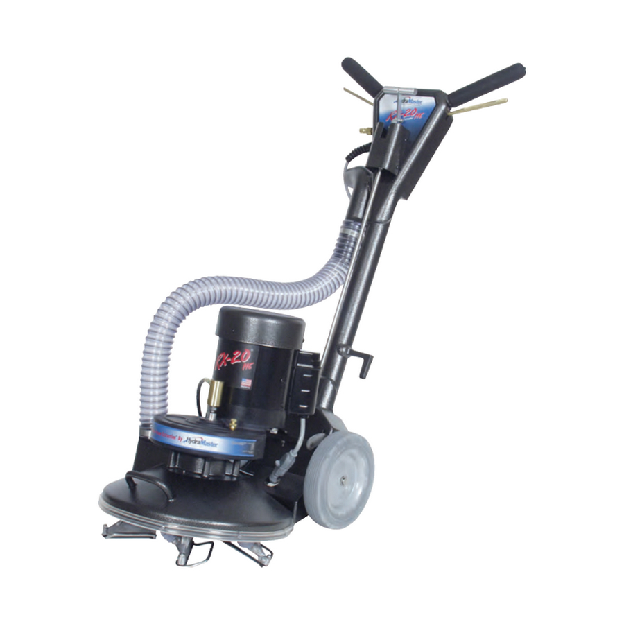
- Page 7 Your new RX-20 is a powerful Rotary Jet Extractor that has been precision engineered to bring you to the state-of-the-art in carpet, tile and grout cleaning. The RX-20’s weight distribution and rotary motion enable the operator to maneuver the unit easily with less fatigue and without back strain.
-
Page 8: Introduction
RX-20 CONTACT INFORMATION If you have any questions regarding the operation, maintenance or repair of this machine, refer to the following information and contact the appropriate HydraMaster department. Hours Telephone Numbers E-mail Addresses Tech Support: Monday-Friday (425) 775-7275 Support techsupport@hydramaster.com 7:00 a.m. -
Page 9: Warnings, Cautions And Notices
RX-20 WARNINGS, CAUTIONS AND NOTICES HydraMaster uses this WARNING symbol throughout the manual to warn of possible injury or death. This CAUTION symbol is used to warn of possible equipment damage. This NOTICE symbol indicates that federal or state regulatory laws may apply, and also emphasizes supplemental information. - Page 10 RX-20 This page intentionally left blank. Introduction: 1-4...
- Page 11 RX-20 2- Machine Specifications RX-20 - 120 V RX-20 - 230 V Length 23” 23” Base Width 16” 16” Height - Standard Up to 43” Up to 43” Weight 70 lbs 70 lbs 1/2 HP Totally Enclosed 1/2 HP Totally Enclosed,...
-
Page 12: Machine Specifications
RX-20 RX-20 - 120 V RX-20 - 230 V Handle Assembly Foam Grips Foam Grips Transportation 8” diameter, 1-1/2” Wide; 8” diameter, 1-1/2” Wide; Wheels Gray, Non-Marking Gray, Non-Marking Electric Cord 50 ft, 14/3 50 ft w/M-F IEC Ends 230 V The base, exhaust manifolds, handle, gear box housing and cleaning heads are all cast aluminum. - Page 13 RX-20 OPTIONAL EQUIPMENT To better meet your business needs, HydraMaster offers these options that you can add to your basic rotary extractor system: If you want this Order this P/N: option: Pad and Bonnet 190-041-020 Driver (Top Photo, Figure 2-1)
- Page 14 RX-20 This page intentionally left blank. Machine Specifications: 2-4...
-
Page 15: Assembly Instructions
The solid shipping plug may be discarded. Remove the protective wrapping material from the wheels. Attach the cleaning head, or star, assembly to the base of the RX-20 (see Figure 3-1). Lean the machine back and rest it on the handle. - Page 16 RX-20 This page intentionally left blank. Assembly Instructions: 3-2...
-
Page 17: Operating Instructions
Solution and Vacuum Hose Connections Your RX-20 is equipped with a 440 male quick connect for the solution hose connection and a 2” O.D. vacuum hose inlet (see Figure 4-1). The vacuum inlet requires a 2” I.D. -
Page 18: Operation
RX-20 Electrical Cord Connection The 50 ft electrical cord on your RX-20 (120 V/60 Hz configuration) is a permanently attached, three-prong grounded line requiring a three-prong, 15 Amp receptacle. A three-prong to two-prong adapter may be used if its ground wire is properly attached to a grounded terminal. -
Page 19: Figure 4-3. Lift Or Lower Handle To Maneuver; Illustration To The
Maneuvering Your RX-20 Your RX-20 maneuvers like a rotary floor machine. To move the RX-20 to the right, lift the handle slightly (see Figure 4-3). The more you lift or lower the handle, the faster the RX-20 will move. Figure 4-3. Lift or Lower Handle to Maneuver; Illustration to the Right... -
Page 20: Figure 4-4. Correct Cleaning Patterns
To familiarize yourself with your RX-20, practice on an open area. Depress both the solution trigger and motor trigger and move the RX-20 slowly in a 3 to 5-ft arc, as shown in Figure 4-4. Figure 4-4. Correct Cleaning Patterns After you have become familiar with the speed and movement of the machine, practice making it hover in one spot. -
Page 21: Cleaning Information
3. DO NOT operate your RX-20 over loose or unraveled carpet seams. The cleaning head may catch and cause further damage. 4. DO NOT operate your RX-20 on concrete floors. It will develop sharp edges on the extraction heads that will damage carpet fibers. -
Page 22: Special Information
With an RX-20, loose yarns form balls and are kicked aside as the cleaning heads revolve. This is normal when aggressive cleaning or even normal vacuuming takes place, as evidenced by a number of dead, loose yarns in the vacuum cleaner bag. -
Page 23: Machine Maintenance
Good care and regular maintenance of your RX-20 will result in a long, dependable life for the unit. Keep in mind that your RX-20 will be in full view of your customer. An RX-20 that is dirty and unkempt in appearance can cause your business or professional image to suffer. -
Page 24: Figure 6-2. Check Jet Spray For Even Flow
RX-20 Check the spray on the jets for even flow. An uneven spray will cause improper flow of the cleaning solution (see Figure 6-2). Do NOT spray the high pressure solution in your face or eyes. Bodily injury can result. -
Page 25: Figure 6-5. Clean Off Debris From Gear Box Shaft
14. Coat the shaft with TKX All-Purpose Lube Gear Box Shaft ® (HydraMaster P/N 000-087-006) or a similar lubricant. Re-install the vacuum head assembly onto the shaft by rotating it counter-clockwise (Figure 6-7). An accumulation of debris in the gear box, if not removed, may damage the gear box oil seal. -
Page 26: Periodic Maintenance
To check the oil level, remove the vent plug and look into the gear box. Turn the star until you can see the inspection hole in the gear. When the RX-20 is sitting flat on a table or the floor, the oil level should be up to, but not above, the middle of the gear. If oil needs to be added, use a quality 80-90 weight gear oil. -
Page 27: Transport And/Or Storage
FREEZE WARNING AND PROTECTION Your RX-20 can suffer damage from freezing, as can any equipment that functions with the use of water. Care must be taken to protect this machine from freezing just as you do your other equipment. - Page 28 RX-20 This page intentionally left blank. Machine Maintenance: 6-6...
-
Page 29: Figure 7-1. Wiring Diagram - 120 V, 60 Hz
RX-20 7- Electrical Diagrams Figure 7-1. Wiring Diagram - 120 V, 60 Hz 6037 7-1: Electrical Diagrams... -
Page 30: Electrical Diagrams
RX-20 Figure 7-2. Wiring Diagram - 230 V, 50 Hz 4503 Rev. A Electrical Diagrams: 7-2... -
Page 31: Assembly Drawings And Parts Lists
RX-20 8 - Assembly Drawings and Parts Lists The following RX-20 major assemblies are detailed in this section: „ Final Assembly Parts List (120V) „ Final Assembly Parts List (230V) „ Final Assembly OS Parts List (230V) „ Base and Drive Train Assembly Parts List „... -
Page 32: Figure 8-1. Final Assembly (120V)
RX-20 Figure 8-1. Final Assembly (120V) 604-999-100 Rev. E 604-999-101 OS Rev. A Assembly Drawings and Parts Lists: 8-2... -
Page 33: Final Assembly Parts List (120V)
RX-20 Final Assembly Parts List (120V) Item Part Number Description 604-054-100 Assembly, Base and Drive Train 604-051-100 Assembly, Upper and Lower Handle 604-053-100 Assembly, Vacuum Head * 604-053-101 Assembly, Vacuum Head OS * 000-033-010 Clamp, Size #32 Hose 000-052-001 Fitting, Swivel (2M2-2 UFS) 000-068-040 Hose, 2”... -
Page 34: Figure 8-2. Final Assembly (230V)
RX-20 Figure 8-2. Final Assembly (230V) 604-999-201 Rev. A - 60 Hz 604-999-202 Rev. A - 50 Hz Assembly Drawings and Parts Lists: 8-4... -
Page 35: Final Assembly Parts List (230V)
RX-20 Final Assembly Parts List (230V) Item Part Number Description Item Part Number Description 604-054-100 Assembly, Base and Drive Train 110V/230V - 60Hz * 000-068-040 Hose, 2” Vacuum - Base to Manifold 604-054-202 Assembly, Base and Drive Train - 230V / 50Hz * 000-068-176 Hose, 3/16”... -
Page 36: Figure 8-3. Final Assembly Os (230V)
RX-20 Figure 8-3. Final Assembly OS (230V) 604-999-203 Rev. A - 60 Hz 604-999-204 Rev. A - 50 Hz Assembly Drawings and Parts Lists: 8-6... -
Page 37: Final Assembly Os Parts List (230V)
RX-20 Final Assembly OS Parts List (230V) Item Part Number Description Item Part Number Description 604-054-100 Assembly, Base and Drive Train 110V/230V - 60Hz * 000-068-040 Hose, 2” Vacuum - Base to Manifold 604-054-202 Assembly, Base and Drive Train - 230V / 50Hz * 000-068-176 Hose, 3/16”... -
Page 38: Figure 8-4. Base And Drive Train Assembly (120V) - View 1 Of 2
RX-20 Figure 8-4. Base and Drive Train Assembly (120V) - View 1 of 2 604-054-100 Rev. E Assembly Drawings and Parts Lists: 8-8... -
Page 39: Base And Drive Train Assembly Parts List
RX-20 Figure 8-5. Base and Drive Train Assembly (120V) - View 2 of 2 604-054-100 Rev. E - 60 Hz Base and Drive Train Assembly Parts List Item Part Number Description 000-006-009 Base w/ Handle - Coated * 000-052-059 Bushing, 1/4” MPT X 1/8” FPT... -
Page 40: Figure 8-6. Base And Drive Train Assembly (230V) - View 1 Of 2
RX-20 Figure 8-6. Base and Drive Train Assembly (230V) - View 1 of 2 604-054-202 Rev. A Assembly Drawings and Parts Lists: 8-10... -
Page 41: Base And Drive Train Assembly Parts List (230V)
RX-20 Figure 8-7. Base and Drive Train Assembly (230V) - View 2 of 2 604-054-202 Rev. A - 50 Hz Base and Drive Train Assembly Parts List (230V) Item Part Number Description 000-006-009 Base w/Handle - Coated 000-052-059 Bushing, 1/4” MPT X 1/8” FPT... -
Page 42: Figure 8-8. Upper And Lower Handle Assembly (120V) - View 1 Of 2
RX-20 Figure 8-8. Upper and Lower Handle Assembly (120V) - View 1 of 2 604-051-100 Rev. I Assembly Drawings and Parts Lists: 8-12... -
Page 43: Figure 8-9. Upper And Lower Handle Assembly (120V) - View 2 Of 2
RX-20 Figure 8-9. Upper and Lower Handle Assembly (120V) - View 2 of 2 604-051-100 Rev. I Close Up of Solution Valve and Mounting Hardware 8-13: Assembly Drawings and Parts Lists... -
Page 44: Upper And Lower Handle Assembly Parts List (120V)
RX-20 Upper and Lower Handle Assembly Parts List (120V) Item Part Number Description Item Part Number Description 000-141-007 Adjusting Rod Assembly 000-105-018 Plate, Serial I.D. 604-051-002 Assembly, Handle Locking Linkage 000-108-012 Protector, Power Cord Relief 000-169-058 Assembly, Valve, Solution - Standard... -
Page 45: Figure 8-10. Upper And Lower Handle Assembly (230V) - View 1 Of 2
RX-20 Figure 8-10. Upper and Lower Handle Assembly (230V) - View 1 of 2 604-051-201 Rev. A 8-15: Assembly Drawings and Parts Lists... -
Page 46: Figure 8-11. Upper And Lower Handle Assembly (230V) - View 2 Of 2
RX-20 Figure 8-11. Upper and Lower Handle Assembly (230V) - View 2 of 2 604-051-201 Rev. A Close Up of Solution Valve and Mounting Hardware Assembly Drawings and Parts Lists: 8-16... -
Page 47: Upper And Lower Handle Assembly Parts List (230V)
RX-20 Upper and Lower Handle Assembly Parts List (230V) Item Part Number Description Item Part Number Description 000-141-007 Adjusting Rod Assembly 000-105-018 Plate, Serial I.D. 604-051-002 Assembly, Handle Locking Linkage 000-106-109 Plug, 230V IEC w/Fuse - Receptacle 000-169-058 Assembly, Valve, Solution - Standard... -
Page 48: Figure 8-12. Vacuum Head Assembly
RX-20 Figure 8-12. Vacuum Head Assembly 604-053-100 Rev. B Assembly Drawings and Parts Lists: 8-18... -
Page 49: Vacuum Head Assembly Parts List
RX-20 Vacuum Head Assembly Parts List Item Part Number Description 000-064-012 Assembly, Vacuum Shoe and Skid 000-052-427 Bushing, 1/8” NPT X 1/8” FPT 000-052-078 Elbow, 1/8” NPT X 45° Street 000-052-440 Fitting, 1/8” NPT Brass Coupling - Machined 000-057-047 Gasket, Felt 000-068-174 Hose, 1”... -
Page 50: Figure 8-13. Vacuum Head Assembly Os
RX-20 Figure 8-13. Vacuum Head Assembly OS 604-053-101 Rev. A Assembly Drawings and Parts Lists: 8-20... -
Page 51: Vacuum Head Assembly Os Parts List
RX-20 Vacuum Head Assembly OS Parts List Item Part Number Description 000-064-012-OS Assembly, Vacuum Shoe and Skid OS 000-052-427 Bushing, 1/8” NPT X 1/8” FPT 000-052-089 Elbow, 1/8” NPT Female 000-057-047 Gasket, Felt 000-068-174 Hose, 1” Vacuum - Gray 000-107-020... -
Page 52: Handle Locking Linkage Assembly Parts List
RX-20 Figure 8-14. Handle Locking Linkage Assembly 604-051-002 Rev. B Handle Locking Linkage Assembly Parts List Item Part Number Description 000-107-097 Link 000-094-030-07 Nut, Adjusting,Linkage - Handle Locking 000-103-012 Pin, 1/4” X 7/8” - Clevis 000-103-013 Pin, Cotter 000-107-256 Plunger, Handle Latching 000-139-006 Ring, 5/8”... -
Page 53: Gear Box Assembly Parts List
RX-20 Figure 8-15. Gear Box 000-059-001 Rev. C Gear Box Assembly Parts List Item Part Number Description 000-042-007 Body, Gear Box 000-041-078 Cover, Gear Box 000-059-004 Gear, Spur - Gear Box Driven Gear 000-150-002 Output Shaft, Spur, Double Lead Thread... -
Page 54: Vacuum Shoe And Skid Assembly Parts List
RX-20 Figure 8-16. Vacuum Shoe and Skid Assembly Vacuum Shoe and Skid Assembly Parts List 000-064-012 Rev. A Item Part Number Description 000-057-048 Gasket, Vacuum Head 000-064-030 Head, Shoe, 4” Cast, One Piece 000-094-058 Nut, #10-32UNF Nylock 000-107-245 Skid, Cast... -
Page 55: Vacuum Shoe And Skid Assembly Os Parts List
RX-20 Figure 8-17. Vacuum Shoe and Skid Assembly OS Vacuum Shoe and Skid Assembly OS Parts List 000-064-012-OS Rev. A Item Part Number Description 000-057-048 Gasket, Vacuum Head 000-064-030 Head, Shoe, 4” Cast, One Piece 000-094-058 Nut, #10-32UNF Nylock 000-107-095... -
Page 56: Solution Valve Assembly Parts List
RX-20 Figure 8-18. Solution Valve Assembly 000-169-058 Rev. C Solution Valve Assembly Parts List Item Part Number Description 000-027-001 Cap, Solution Valve - Brass 000-097-011 O-Ring, 5/8” X 1/16” 000-155-003 Spring, Solution Valve 600-012-002 Assembly, Valve Stem - Standard 600-012-001... -
Page 57: Valve Stem Assembly Parts List
RX-20 Figure 8-19. Valve Stem Assembly 600-012-002 Rev. A Valve Stem Assembly Parts List Item Part Number Description 000-097-022 O-Ring, 3/32”X1/16” W 000-097-010 O-Ring, Valve Plunger- Large 000-107-129 Plunger, Solution Valve 000-139-003 Ring, Solution Valve Keeper - Brass 000-139-004 Ring, Solution Valve Stem - Snap Ring- S/S... - Page 58 RX-20 This page intentionally left blank. Assembly Drawings and Parts Lists: 8-28...
-
Page 59: Repair And Replacement
9 - Repair and Replacement FELT VACUUM SEAL The felt vacuum seal plays an important part in the optimum performance of your RX-20. If it is worn or unlubricated, it will not form a proper seal. Lack of a proper seal will impair the vacuuming capabilities of the unit and therefore leave behind more water in the carpet than is desirable. -
Page 60: High Pressure Valve Assembly
RX-20 HIGH PRESSURE VALVE ASSEMBLY In the event that the valve assembly needs to be replaced, follow this procedure: Remove the 440 male quick connect with a wrench. Remove the five hex head screws in the back plate on the handle and lift the back plate off. -
Page 61: Troubleshooting
RX-20 10 - Troubleshooting 1.0 Low Vacuum Flow at the Cleaning Heads Possible Cause Solution 1.1 Hub not sealing properly. Replace felt seal with a lubricated one. 1.2 Restricted air flow. Remove hoses from the vacuum shoe and skid assembly, and clear them of debris. - Page 62 Replace damaged oil seal. Refill gearbox with oil. 5.1 Loose or ruptured oil seal. 6.0 No Power Possible Cause Solution 6.1 RX-20 wiring or power Have an electrician inspect unit for possible wiring source. or motor problems. 6.2 Overload power source.
-
Page 63: Warranty Information
If you have moved to a new area or have purchased a used machine and need information regarding your local distributor, call HydraMaster at (425) 775-7272 or email us at: custsvc@hydramaster.com. When calling your distributor, be sure to have the machine’s information; model and serial number, ready for the service representative. - Page 64 RX-20 This page intentionally left blank. Warranty Information: 11-2...
Need help?
Do you have a question about the RX-20 and is the answer not in the manual?
Questions and answers