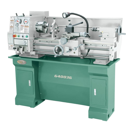
Grizzly G4003G Owner's Manual
Gunsmith's lathe
Hide thumbs
Also See for G4003G:
- Parts list (21 pages) ,
- Owner's manual (76 pages) ,
- Owner's manual (112 pages)
Table of Contents
Advertisement
Advertisement
Table of Contents

Related Manuals for Grizzly G4003G


Summary of Contents for Grizzly G4003G
- Page 1 MODEL G4003G GUNSMITH'S LATHE OWNER'S MANUAL COPYRIGHT © MAY, 2007 BY GRIZZLY INDUSTRIAL, INC., REVISED OCTOBER, 2007 (TR) WARNING: NO PORTION OF THIS MANUAL MAY BE REPRODUCED IN ANY SHAPE OR FORM WITHOUT THE WRITTEN APPROVAL OF GRIZZLY INDUSTRIAL, INC.
- Page 2 ���� ������ �������� �������� ������ ������������ �� ��� ������ ������ ���������� ����������� ��� ������� �� ���� ������������������ ������� �� ����� ���������� ��� ������ ��� ������������ ����� �� ���� ������ ��� ������ �� ������� �������� ������� ��������� ����������� ������������� �� ������ ���...
-
Page 3: Table Of Contents
Change Gears and Metric Threading ... 28 Carriage Handwheels ... 29 Tool Post & Holder ... 30 Tailstock Controls ... 30 G4003G Gunsmith's Lathe Table of Contents SECTION 5: ACCESSORIES ... 31 SECTION 6: MAINTENANCE... 33 Basic Maintenance ... 33 Lubrication ... -
Page 4: Introduction
Grizzly’s com- mitment to customer satisfaction. We are pleased to provide this manual with the Model G4003G. It was written to guide you through assembly, review safety considerations, and cover general operating procedures. It repre- sents our effort to produce the best documenta- tion possible. -
Page 5: Machine Data Sheet
Machine Data Sheet Customer Service #: (570) 546-9663 · To Order Call: (800) 523-4777 · Fax #: (800) 438-5901 MODEL G4003G GUNSMITH'S BENCH TOP LATHE WITH GUNSMITH'S BENCH TOP LATHE WITH STAND Product Dimensions: Weight... 1213 lbs. Length/Width/Height... 61 x 26 x 54-1/2 in. - Page 6 The information contained herein is deemed accurate as of 11/12/2007 and represents our most recent product specifications. Model G4003G Due to our ongoing improvement efforts, this information may not accurately describe items previously purchased. PAGE 2 OF 3 G4003G Gunsmith's Lathe...
-
Page 7: Identification
N. Halogen Work Light O. Follow Rest P. Tool Rest G4003G Gunsmith's Lathe Identification Figure 1. Model G4003G identification. Q. Compound Rest Handwheel R. Tailstock Spindle and Center S. Tailstock Spindle Lock Lever Tailstock Spindle Handwheel U. Back Splash Guard V. -
Page 8: Section 1: Safety
�� ���� ������ ��������� ��� ���� �������� ���������������������������������������������� ��� �������� ����� ���� ������ ��� ������� ������� ����� ����������� ����� ��������� ��� �������� ������������������������������������� �� ����� ������� ��������� ���� ����� �� ����� ��� ��������� �� ��������� ����� �� �������� ������������������ ������������������������������������ ��������� ����������� G4003G Gunsmith's Lathe... - Page 9 ��� �������� ��������� ���� ������ ����������������������������������������� �������������������������������������������� ������������������������������������� ��� ���� ���� ������ ��� �� ����� ��� ���� ��������� ������ ����� ���������� G4003G Gunsmith's Lathe ��� ������ ��������������������������������������� ����� ���� ���������� ��������� ������� ����� ����������������� ��� ����� ������ ����� ��������������������� �������������������������������������������...
-
Page 10: Additional Safety Instructions For Lathes
ELIMINATING A PROJECTILE HAZARD: Always remove the chuck key, and never walk away from the lathe with the chuck key installed. SECURING A WORKPIECE: Make sure workpiece is properly held in chuck before starting lathe. -
Page 11: Glossary Of Terms
The following is a list of common definitions, terms and phrases used throughout this manual as they relate to this lathe and metalworking in general. Become familiar with these terms for assembling, adjusting or operating this machine. Your safety is VERY important to us at Grizzly! Arbor: A machine shaft that supports a cutting tool. -
Page 12: Section 2: Circuit Requirements
DO NOT connect the machine to the power source until instructed to do so. Amperage Draw The Model G4003G motor draws the following amps under maximum load: Motor Draw at 220V ... 9 Amps Circuit Requirements... -
Page 13: Section 3: Setup
Use power lifting equip- ment such as a fork lift or hoist to move heavy items. G4003G Gunsmith's Lathe Items Needed for Setup The following items are needed to complete the setup process, but are not included with your... -
Page 14: Inventory
Qty. Figure 3. Installed components. Figure 4. Packaged components. NOTICE Some hardware/fasteners on the inventory list may arrive pre-installed on the machine. Check these locations before assuming that any items from the inventory list are miss- ing. G4003G Gunsmith's Lathe... -
Page 15: Site Considerations
The unpainted surfaces are coated with a waxy oil to prevent corrosion during shipment. Remove this protective coating with a solvent cleaner or citrus-based degreaser such as Grizzly’s G7895 Citrus Degreaser. To clean thoroughly, some parts must be removed. ���... -
Page 16: Mounting To Shop Floor
Mounting to Shop Floor We recommend that you bolt your lathe to the floor. Because floor materials may vary, floor mounting hardware is not included. Since this is a precision machine, it is important to level the machine with a precision level when mounting. -
Page 17: Lifting & Moving
Figure 8. Figure 8. Lifting strap locations. G4003G Gunsmith's Lathe Move the apron toward the right to help bal- ance the load, as shown in Figure 8. Position the chip pan on top of the base assembly so that the six lathe mounting holes align with top holes of the cabinets. -
Page 18: Test Run & Break-In
(Disengaged) Return the spindle rotation ON/OFF lever to STOP, reset the emergency stop button, restart the lathe, and let the lathe run for a minimum of 10 minutes in both directions. 10. Turn the lathe OFF, and move the speed levers to C and 1 so the spindle will rotate at 200 RPM. -
Page 19: Tailstock Setup
Figure 12. Finished dead center. Place the live center in your tailstock. G4003G Gunsmith's Lathe Attach a lathe dog to the bar stock from Step 1 and mount it between the centers (as shown in Figure 13). - Page 20 (Figure 16). Turn another 0.010'' off of the stock and check for taper. Repeat as necessary until the desired amount of accuracy is achieved. Adjustment Screw Figure 16. Tailstock adjustment locations. G4003G Gunsmith's Lathe...
-
Page 21: Section 4: Operation
OMMEND that you read books, trade maga- zines, or get formal training before begin- ning any projects. Regardless of the con- tent in this section, Grizzly Industrial will not be held liable for accidents caused by lack of training. NOTICE Complete the Test Run &... -
Page 22: Mounting Chuck And Faceplate
Mounting Chuck and Faceplate The Model G4003G is shipped with the 3-jaw chuck installed. This is a scroll-type chuck, mean- ing that all three jaws move in unison when adjusted. The 4-jaw chuck, on the other hand, features independent jaws. This chuck is used for square or unevenly-shaped stock. - Page 23 60˚ and tap again. Make sure all the marks on the cams and spindle are in proper alignment. G4003G Gunsmith's Lathe To install a chuck: DISCONNECT LATHE FROM POWER! Place a piece of plywood across the lathe bed and position it just under the spindle.
-
Page 24: Centers
The tailstock barrel and live center have an MT#3 taper. Included with this lathe is an MT#3 to MT#5 spindle sleeve. If you need to install a center in the spindle when using the face plate, you can do so by using this adapter sleeve. -
Page 25: Steady Rest
Oil the finger bearings and the rolling sur- faces while in use to assist in friction-free support. G4003G Gunsmith's Lathe The follow rest is normally used with small diam- eter stock to prevent the workpiece from “spring- ing” under pressure from the turning tool. -
Page 26: Feed Direction Lever
As the chuck rotates it aligns the gears and the lever will engage. Your lathe can cut left or right while feeding or threading, and it can cut across both ways for fac- ing operations. This feed direction is controlled by the feed direction lever shown in Figure 25. -
Page 27: Gearbox Levers
If it does not, rotate the feed rod or chuck by hand while maintaining gentle pressure on the lever. G4003G Gunsmith's Lathe Feed Rate Chart The far left column in the feed rate chart (Figure 28) shows which change gears must be installed so the chart will be accurate. -
Page 28: Carriage/Cross Feed Lever
When the cap screw is loosened, the thread dial housing pivots so its gear can be engaged or disengaged from the lead screw. When engaged, the dial will turn when the lead screw and spindle are turning. G4003G Gunsmith's Lathe... - Page 29 Figure 31. Thread dial chart. G4003G Gunsmith's Lathe While other thread pitches may be achieved, the G4003G is designed so that no gear changes are needed for cutting inch threads. However, you will have to move the feed direc- tion lever to the direction of thread you want to cut, and then move the feed rod lever to the right.
-
Page 30: Change Gears And Metric Threading
Change Gears and Metric Threading This lathe can cut 29 different metric threads, but gear changes are required to cut all of the listed metric threads. These gear changes take place on the left hand end of the machine (Figure 33). -
Page 31: Carriage Handwheels
50 teeth and the G position change gear needs 60 teeth. A diagram on the left side of the chart shows that the G4003G Gunsmith's Lathe 50 tooth change gear meshes with the 91 tooth middle gear and the 60 tooth change gear mesh- es with the 86 tooth middle gear. -
Page 32: G4003G Gunsmith's Lathe
This lever locks the tailstock barrel in place. Side Lock Lever & Torque Tightening This removable lever locks the tailstock in place on the lathe bed. The socket that it fits into will accept a ⁄ " drive torque wrench. -
Page 33: Section 5: Accessories
G5701 G5704 G5703 G5700 Figure 40. Series 200 quick change tool holders. G4003G Gunsmith's Lathe H6095—Digital Readout (DRO) This is one of the finest DRO's on the market today. Features selectable resolution down to 5µm, absolute/incremental coordinate display, arc function, radius/diameter function, master... - Page 34 G7040—Carbide Inserts for Steel (5 pk) G7048—Carbide Inserts for Cast Iron (5 pk) Figure 45. G7038Z Boring Bar. G7030—Threading Tool Holder G7041—Carbide Inserts for Steel (5 pk) G7049—Carbide Inserts for Cast Iron (5 pk) Figure 46. G7030 Threading Tool Holder. G4003G Gunsmith's Lathe...
-
Page 35: Section 6: Maintenance
SECTION 6: MAINTENANCE Figure 49. Quick change gearbox lubrication. -33- G4003G Gunsmith's Lathe... -
Page 36: Lubrication
It is a good idea to remove the tailstock once a month and wipe the bottom thoroughly and replace. G4003G Gunsmith's Lathe... -
Page 37: Section 7: Service
Gear change 1. Gears not aligned in headstock. levers will not shift into position. G4003G Gunsmith's Lathe Troubleshooting Possible Solution 1. Turn the main power panel switch ON. 2. Rotate emergency switch so it pops out. 3. Seek an electrician to troubleshoot and repair the shop power supply. - Page 38 1. Adjust gear positions or replace. 2. Loosen gib screw(s) slightly. 3. Tighten. 4. Correct for cause of shear pin breakage, and replace shear pin. 1. Turn lever counterclockwise. ⁄ of the total screw(s) slightly, lubricate G4003G Gunsmith's Lathe...
-
Page 39: Gibs
Gibs There are three main gib adjustments for the Model G4003G. They are: the cross-slide gib, the compound slide gib and the saddle gib. Cross-slide Gib, see Figure 52 The gib on the cross-slide is adjusted by the two screws located at each end. To adjust, loosen the set screw located along the edge of the cross-slide. - Page 40 It is important that the gib be properly adjusted. A loose gib will cause finish problems in a workpiece. A gib adjusted too tightly will cause premature wear. Figure 54. Saddle lock bolt and saddle gib screws. -38- G4003G Gunsmith's Lathe...
-
Page 41: Bearing Preload
Figure 58. Introducing detectable end-play. G4003G Gunsmith's Lathe Place a dial indicator on the cross slide and move the carriage toward the headstock until the contact point of the indicator touches the spindle face (Figure 59). - Page 42 Install the chuck and tighten the jaws. Set the spindle speed to its highest setting. Connect the lathe to power and turn the lathe spindle ON. Let the lathe run for 20 minutes. Turn the spindle OFF, disconnect lathe from power, and check the temperature of the spindle.
-
Page 43: Wiring-Electrical Box
Wiring—Electrical Box Figure 62. Electrical box wiring. -41- G4003G Gunsmith's Lathe... - Page 44 � � �� � � ���� ���� ���� ���� ��������� �������� ��� ���� ���� ���� ���� �� � � � �� � � � � � �� � � � � � � ��� ��� ������������� �������������� G4003G Gunsmith's Lathe...
-
Page 45: Wiring-Motor & Control Panel
Wiring—Motor & Control Panel Figure 63. Motor wiring. Figure 64. Control panel wiring. -43- G4003G Gunsmith's Lathe... - Page 46 � ��� �������������� -44- ����� �������������������������� ��� ��������� ������ ����� ������ �� �� �� �� �� ����� ��������� ������ ������ ������� ����� � ����������� ����� �� � ������ ������ � � �� ����� ����� � �� � G4003G Gunsmith's Lathe...
-
Page 47: Wiring-Plug, Light & Spindle Switch
Wiring—Plug, Light & Spindle Switch Figure 65. Work light wiring. Figure 66. Spindle ON/OFF switch. -45- G4003G Gunsmith's Lathe... - Page 48 ������� ���� ����� ��� �������������� ��� �������������� -46- ������ ��� � ��� ��� ��� ���� ���� ��� ������������ � � ������� ������ ������ � � � � � � � � � � ����� ���� ������ �� ���� ���� G4003G Gunsmith's Lathe...
-
Page 49: Section 8: Parts
HEX WRENCH 8MM PAW06M HEX WRENCH 6MM PAW05M HEX WRENCH 5MM PAW04M HEX WRENCH 4MM PAW02M HEX WRENCH 2MM P4003G0022 SPIDER SCREW P4003G0023 LIVE CENTER MT#3 G4003G Gunsmith's Lathe Components � � ��� �� �� � �� ����� �� �� ��... -
Page 50: Gearbox Gearing
Gearbox Gearing -48- G4003G Gunsmith's Lathe... - Page 51 P4003G0134 COVER PSB27M CAP SCREW M6-1 X 14 P4003G0136 COMPRESSION SPRING PSB84M CAP SCREW M10-1.5 X 35 G4003G Gunsmith's Lathe REF PART # DESCRIPTION P4003G0138 CAM LOCK P4003G0139 KEY 8 X 8 X 80 PK43M KEY 8 X 8 X 45 PSB80M CAP SCREW M3-.5 X 8...
-
Page 52: Gearbox Shifters
Gearbox Shifters -50- G4003G Gunsmith's Lathe... - Page 53 CAP SCREW M6-1 X 12 P4003G0202 SPECIAL WASHER P4003G0203 GEAR 40T PK12M KEY 5 X 5 X 30 PSB26M CAP SCREW M6-1 X 12 G4003G Gunsmith's Lathe PART # DESCRIPTION P4003G0206 SPECIAL WASHER P4003G0207 STEP GEAR P6202 BALL BEARING 6202ZZ...
-
Page 54: Quick Change System
��� ��� ��� ��� ��� ��� ��� ��� ��� ��� ��� ��� ��� ��� ��� ��� ��� ��� ��� ��� ��� ��� ��� ��� ��� ��� ��� ��� ��� ��� ��� ��� ��� ��� ��� ��� ��� G4003G Gunsmith's Lathe... - Page 55 ROLL PIN 4 X 30 P4003G0334 SHIFT FORK PSB26M CAP SCREW M6-1 X 12 P4003G0336 SPECIAL WASHER P4003G0337 GEAR 16T P4003G0340 GEAR 32T G4003G Gunsmith's Lathe REF PART # DESCRIPTION P4003G0341 GEAR 16T P4003G0342 GEAR 32T P4003G0343 GEAR 16T P4003G0344 GEAR 16T...
-
Page 56: Apron
Apron -54- G4003G Gunsmith's Lathe... -
Page 57: Apron Parts List
ROLL PIN 5 X 24 P4003G0429 STEEL BALL 6MM P4003G0430 COMPRESSION SPRING PSS03M SET SCREW M6-1 X 8 PSB30M CAP SCREW M6-1 X 45 P4003G0433 BOSS G4003G Gunsmith's Lathe Apron Parts List REF PART # PW03M PSB29M P4003G0436 P4003G0437 PSS17M P4003G0439 P4003G0440 P4003G0441... -
Page 58: Saddle
��� ��� ��� ��� ��� ��� ��� ��� ��� ��� ��� ��� ��� ��� ��� ��� ��� ��� ��� ��� ��� ��� ��� ��� ��� ��� ��� ��� ��� ��� ��� ��� ��� ��� ��� ��� -56- G4003G Gunsmith's Lathe... -
Page 59: Saddle Parts List
P4003G0513 P4003G0514 BUSHING P4003G0515 BRASS CROSS SLIDE NUT M8 X 12 P4003G0518 SLIDE PLATE PFH21M FLAT HD SCR M8-1.25 X 25 P4003G0520 WIPER G4003G Gunsmith's Lathe Saddle Parts List REF PART # PS57M P4003G0522 P4003G0523 P4003G0524 PB19M P4003G0526 P4003G0528 P4003G0529... -
Page 60: Compound Slide
617A P4003G0617A HANDLE SMALL PSS07M PSB28M P4003G0640 P4003G0641 ��� ��� ��� ��� ��� ��� ��� ��� DESCRIPTION BRACKET THRUST BEARING 8101 GRADUATED DIAL SPANNER NUT BRACKET HANDLE LARGE SET SCREW M5-.8 X 5 CAP SCREW M6-1 X 15 SPECIAL SCREW G4003G Gunsmith's Lathe... -
Page 61: Tailstock
P4003G0710 BRACKET P4003G0711 GRADUATED DIAL PSB02M CAP SCREW M6-1 X 20 P4003G0713 HANDWHEEL P4003G0714 HANDLE PN09M HEX NUT M12-1.75 P4003G0716 HANDLE G4003G Gunsmith's Lathe Tailstock ��� ��� ��� ��� ��� ��� ��� ��� ��� REF PART # P4003G0717 P4003G0718 P4003G0719... -
Page 62: Lathe Bed & Motor
& motor breakdown Lathe Bed & Motor -60- G4003G Gunsmith's Lathe... -
Page 63: Base
Base -61- G4003G Gunsmith's Lathe... - Page 64 P4003G0827 SPECIAL NUT P4003G0828 SPACER BLOCK P4003G0829 RIGHT STAND BASE P4003G0830 RIGHT BRACKET P4003G0833 FRONT PLATE P4003G0834 LEFT BRACKET PN01M HEX NUT M6-1 P4003G0836 LEFT STAND BASE PW10M FLAT WASHER 14MM PB129M HEX BOLT M14-2 X 45 G4003G Gunsmith's Lathe...
-
Page 65: Feed Rod
ROLL PIN 6 X 55 PSS02M SET SCREW M6-1 X 6 P4003G0906 COLLAR P4003G0907 FEED ROD P4003G0908 PRP39M ROLL PIN 4 X 20 P4003G0910 SPRING 7020 G4003G Gunsmith's Lathe Feed Rod ��� ��� ��� ��� ��� ��� ��� ��� ��� ���... -
Page 66: Machine Labels
MUST maintain the original location and readability of the labels on the machine. If any label is removed or becomes unreadable, REPLACE that label before using the machine again. Contact Grizzly at (800) 523-4777 or www.grizzly.com to order new labels. -64-... -
Page 67: Electrical Components
1204 P4003G1204 THERMAL RELAY 1205 P4003G1205 CONTACTOR GSC1-1801 1206 P4003G1206 CONTACTOR JZC3 40D 1207 P4003G1207 GROUND TERMINAL BLOCK 1208 P4003G1208 TERMINAL BLOCK 12-POLE G4003G Gunsmith's Lathe ���� ���� ���� ���� ���� ���� ���� REF PART # 1209 P4003G1209 1210 P4003G1210... -
Page 68: Steady & Follow Rest Assemblies
COMPLETE FOLLOW REST ASSY HANDLE SET SCREW M6-1 X 6 BUSHING SPECIAL SCREW FINGER BEARING W/ SLEEVE SET SCREW M6-1 X 8 HEX NUT M6-1 SET SCREW M6-1 X 20 BODY CASTING CAP SCREW M8-1.25 x 60 G4003G Gunsmith's Lathe... - Page 69 ���������������������������������������������������������������������������������� � ������������������������������������������������������������������������������������ ����� ����������������������� ������ � ������������������������ ���� ��������������������� ���������������������������� ������ ������������������������ ���������� � ���������������� ���������������������������� ������������������������������� ��������������������������� ��� ��������� ����������� �� ����� �� � ��������� ������ �� ���� �� ���� ��� ��������� �������� �� ���� �� ������� ������ �������� ��� ��������� �� ������� ��� ����������� �� �������� ������������� ���...
- Page 70 ���������������������� ���������������������� ����������������������������������� ������� ����������� ���� ���� ��� ���� ����������� �� ���������� ����������������������������������� ������������������������������������� �������������������������������������� �������������������������������������� ����� ����� ����...
-
Page 71: Warranty And Returns
WARRANTY AND RETURNS Grizzly Industrial, Inc. warrants every product it sells for a period of 1 year to the original purchaser from the date of purchase. This warranty does not apply to defects due directly or indirectly to misuse, abuse, negligence, accidents, repairs or alterations or lack of maintenance. - Page 72 ��� ������ ��� ���� ���� ������� ����� ��� ������� ����� ��� �������� ��� ������� � � � ���� ����� ��� � � �������� ������ ��� � ����� ������ � �� ��� �������� ������� � ������ �������� ������ ������� ������ �� ����� ������...
Need help?
Do you have a question about the G4003G and is the answer not in the manual?
Questions and answers