Table of Contents
Advertisement
© COPYRIGHT 2005 by HUFFY SPORTS
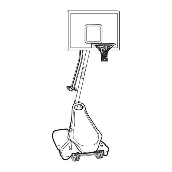
Portable Basketball System
Owners Manual
Customer Service Center
• N53 W24700 South Corporate Circle • Sussex, WI 53089 • U.S.A.
WARNING!
READ AND UNDERSTAND
OPERATOR'S MANUAL
BEFORE USING THIS UNIT.
FAILURE TO FOLLOW
OPERATING INSTRUCTIONS
COULD RESULT IN INJURY
OR DAMAGE TO PROPERTY.
Toll-Free Customer Service Number for U.S: 1-800-558-5234,
For Canada: 1-800-284-8339,
For Europe: 00 800 555 85234 (Sweden: 009 555 85234),
For Australia: 1-800-632-792
Internet Address: www.huffysports.com
REQUIRED TOOLS AND MATERIALS
• Two People
• Wood Board (Scrap)
• Tape Measure
• Step Ladder 8 ft. (2.4 m)
• Tape
• Garden Hose or Sand 360 lb. (163 kg)
• Hammer
• Wrenches: (Two) 3/4", (One) 1/2" (Two) 9/16"or
equivalent sockets, (One) 1/2" Deep well socket
with extension and socket wrench
• Support Table
• Phillips Head Screwdriver
• 5/32 Allen Wrench
1
:
04/05
ID# 21179004
Advertisement
Table of Contents

Related Manuals for HYDRA-RIB Portable Basketball System


Summary of Contents for HYDRA-RIB Portable Basketball System
-
Page 1: Owners Manual
Portable Basketball System Owners Manual Customer Service Center • N53 W24700 South Corporate Circle • Sussex, WI 53089 • U.S.A. REQUIRED TOOLS AND MATERIALS WARNING! • Two People • Wood Board (Scrap) • Tape Measure READ AND UNDERSTAND • Step Ladder 8 ft. (2.4 m) OPERATOR'S MANUAL •... - Page 2 WARNING FAILURE TO FOLLOW THESE WARNINGS MAY RESULT IN SERIOUS INJURY AND/OR PROPERTY DAMAGE. Owner must ensure that all players know and follow HEIGHT ADJUSTMENT these rules for safe operation of the system. • DO NOT HANG on the rim or any part of the system including backboard, support braces or net.
-
Page 3: Safety Instructions
SAFETY INSTRUCTIONS FAILURE TO FOLLOW THESE SAFETY INSTRUCTIONS MAY RESULT IN SERIOUS INJURY OR PROPERTY DAMAGE AND WILL VOID WARRANTY. Owner must ensure that all players know and follow these rules for safe operation of the system. To ensure safety, do not attempt to assemble this system without following the instructions carefully. Proper and complete assembly, use, and supervision are essential for proper operation and to reduce the risk of accident or injury. - Page 4 Get to know the basic parts of your basketball system... FRONT VIEW BACK VIEW BACKBOARD ELEVATOR ASSEMBLY TOP POLE BOTTOM POLE MIDDLE POLE STRUTS FRONT BASE COVER WHEEL CARRIAGE ASSEMBLY ID# 21179004 04/05...
-
Page 5: Parts List
PARTS LIST (SEE HARDWARE IDENTIFIER) Item Qty Part No. Description Item Qty Part No. Description 908164 Top Pole Section 207103 Pole Cap 908114 Middle Pole Section (with Label) 908119 Elevator Tube 908165 Bottom Pole Section 808115 Pole Bracket 900223 Wheel Bracket 206340 Nut, Nylock, 1/2 -13 206940... - Page 6 HARDWARE IDENTIFIER (BOLTS & SCREWS) Item #40 (8) Item #9 (1) Item #10 (1) Item #12 (1) Item #19 (1) Item #21 (1) Item #23 (1) Item #13 (1) Item #31 (1) Item #26 (4) Item #38 (2) Item #41 (1) Item #43 (2) Item #50 (4) Item #46 (2)
- Page 7 HARDWARE IDENTIFIER (NUTS, WASHERS & METAL SPACERS) Item #22 (15)* Item #20 (6) Item #11 (9) Item #55 (2) Item #47 (5)* Item #45 (1) Item #37 (9) Item #28 (3) Item #60 (2) Item #44 (2) HARDWARE IDENTIFIER (PLASTIC SPACERS & CAPS) Item #15 (1) Item #24 (2) Item #7 (4)
-
Page 8: Assembly
SECTION A: ASSEMBLE THE POLES Correctly identify each pole section. Mark pole sections with tape as shown. 5" 5" TAPE TAPE (not supplied) (not supplied) (13 cm) (13 cm) Bounce middle pole section (2) into top pole section (1) together using a wood scrap as shown until they no longer move toward taped reference mark. - Page 9 While maintaining alignment, bounce assembly and lower section (3) together as shown until they no longer move toward taped reference mark. IMPORTANT!: Smaller holes (11/32"\0.87 cm) in the top pole section should face toward the front of the system. IMPORTANT!: Holes in the top (1) and bottom pole (3) sections MUST align correctly to...
- Page 10 SECTION B: ASSEMBLE THE BASE This is what your system will look like when you’ve finished this section. HARDWARE USED IN THIS SECTION TOOLS REQUIRED FOR THIS SECTION (not actual size) 1/2” AND 9/16” Item #9 AND/OR Item #7 Item #10 Item #15 Item #13 Item #11...
- Page 11 Insert axle (5) through wheel bracket (4). Secure wheels (62) to axle using pushnuts (7). Carefully tap pushnuts onto axle with hammer or mallet Install wheel assembly to base (8) using bolt (9), and nut (22) as shown. 04/05 ID# 21179004...
- Page 12 Install rod (12) through holes in bottom pole section (3) and eyebolt (13). Insert pole assembly into tank (8) and through center hole on wheel assembly as shown. Secure pole assembly with anchor strap (53), washer (11), and lock nut (47). WARNING! TWO PEOPLE REQUIRED FOR THIS PROCEDURE.
- Page 13 Secure tank struts (14) to pole as shown. Place cap (15) over exposed end of bolt as shown. WARNING! TWO PEOPLE REQUIRED FOR THIS PROCEDURE. FAILURE TO FOLLOW THIS WARNING COULD RESULT IN NOTE: SERIOUS INJURY AND/OR PROPERTY DAMAGE. ORIENTATION OF STRUTS Rotate non-secured ends of tank struts (14) outward to mounting holes in tank as shown.
- Page 14 Secure ends of tank struts (14) to tank as shown. Repeat for opposite side. WARNING! TWO PEOPLE REQUIRED FOR THIS PROCEDURE. FAILURE TO FOLLOW THIS WARNING COULD RESULT IN SERIOUS INJURY AND/OR PROPERTY DAMAGE. Install upper pivot bracket (16) to front of base using bolt (19), washer (20) and nut (47) as shown.
- Page 15 Insert bolt (21) through lower pivot bracket (17) as shown; bolt (21) will be secured during Step 10. Carefully place base assembly on its side. Install lower pivot bracket (17) with bolt (23), washers (20), and lock nut (47) as shown. IMPORTANT!: DO NOT OVER TIGHTEN...
- Page 16 Insert axle (5) through wheel bracket (4). Secure wheels (6) to axle using pushnuts (7). Carefully tap pushnuts onto axle with hammer or mallet IMPORTANT!: SIDE OF WHEEL WITH LONGER PLASTIC AXLE NEEDS TO FACE THE WHEEL BRACKET. Position base as shown. Secure wheel bracket assembly with disc (61), washer (20) and nut (47) as shown.
- Page 17 SECTION C: ASSEMBLE THE ELEVATOR SYSTEM & BACKBOARD This is what your system will look like when you’ve finished this section. HARDWARE USED IN THIS SECTION TOOLS REQUIRED FOR THIS SECTION (not actual size) Item #22 Item #24 (2) 1/2”, (2) 9/16" AND (2) 3/4” Item #11 Item #25 Item #31...
- Page 18 Securely rest the assembly on sawhorse. Install pole bracket (36) to top pole as shown (FIG.A) using bolts (38), metal spacers (60) and nuts (22). Reference finished assembly (FIG.B.) WARNING! TWO PEOPLE REQUIRED FOR THIS PROCEDURE. FAILURE TO FOLLOW THIS WARNING COULD RESULT IN SERIOUS INJURY AND/OR PROPERTY DAMAGE.
- Page 19 Identify elevator tubes. Install triangle plates (33) and elevator tubes (35) to top pole section (1) as shown. Install pole cap (34). Toward Toward Pole Board Upper and Lower Elevator Tubes COMPLETED ASSEMBLY 04/05 ID# 21179004...
- Page 20 Attach label (57) to window (27). COMPLETED ASSEMBLY IMPORTANT!: LINE UP THE TOP EDGE OF THE LABEL WITH THE TOP EDGE OF THE WINDOW. Remove packaging materials and zip ties from handle assembly (30). Snap window into handle assembly (30). COMPLETED ASSEMBLY ID# 21179004 04/05...
- Page 21 Insert strut assembly (29) over inner channel (30A) and between outer channel (B). Rest at angle shown in FIG. A. Line up holes in strut bracket to holes in outer channel (30B) Strut bracket COMPLETED ASSEMBLY ORIENT STRUT ASSEMBLY SO CLIP-HANDLE FACES LONG SIDE OF CHANNELS WARNING! FIG.A...
- Page 22 Attach hook (58) to strip (56) and secure with bolt (59) and nut (55). Bring strip (56) through top of height indicator Install hook and strip (56) assembly window (27) underneath tabs and insert through into handle assembly. bottom end of height indicator window (27). IMPORTANT!: TO AVOID RAPID EXTENSION OF STRUT...
- Page 23 Attach strut (29) to pole bracket (36) with bolt (31), washers (11), and nut (55) as shown. Slip plastic spacers (25) onto metal spacer (44) that is already inserted into handle assembly. Then, secure handle assembly to elevator tubes (35) using bolts (40), plastic spacers (24) and nuts (37).
- Page 24 Secure strap and hook assembly to upper elevator arms (35) using bolt (40), plastic spacers (32) and nut (37) as shown. IMPORTANT! DO NOT OVER TIGHTEN HOOK MUST ROTATE FREELY TO INDICATE HEIGHT COMPLETED ASSEMBLY ID# 21179004 04/05...
- Page 25 Install spacers (28) onto backboard brackets (48) with bolts (64, 46), washers (20) and lock nuts (55, 47) as shown. Assemble lower elevator tubes (35) as shown. NOTE: Tighten bolt (40) in locknut (37) until flush (even) with the outer edge of the locknut.
- Page 26 Refer To Bolt bracket to board using bolts, washers Instructions (20), and foam pad (65) as shown. Do not Included With over-tighten. Rim Hardware For Rim Assembly. (227 Goal Box) Refer To Instructions NOTE: Included With Place two bolts through UPPER Rim Hardware holes of orange bracket only, as For Rim...
- Page 27 SECTION D: INSTALL FRONT COVER & HANDLE Upright system and fill base (8) with water (approx. 40 gallons) and snap cap (51) in place. WARNING! TWO PEOPLE REQUIRED FOR THIS PROCEDURE. FAILURE TO FOLLOW THIS WARNING COULD RESULT IN SERIOUS INJURY AND/OR PROPERTY DAMAGE.
- Page 28 SECTION E: SECURING THE SYSTEM Roll assembly to desired playing area. Secure assembly to ground using strap (53) and tie down stake (52). ID# 21179004 04/05...
-
Page 29: Height Adjustment
SECTION F: APPLY HEIGHT AND MOVING LABEL Apply Height Adjustment and Moving Label (54) to front of pole, where it is clearly visible. NOTE: Remove strut locking clip. Peel protective film from surface of acrylic backboard prior to use. HEIGHT ADJUSTMENT MOVING SYSTEM 1.
Need help?
Do you have a question about the Portable Basketball System and is the answer not in the manual?
Questions and answers