Table of Contents
Advertisement
Quick Links
Advertisement
Table of Contents

Related Manuals for Edimax IC-3115W


Summary of Contents for Edimax IC-3115W
- Page 1 IC-3115W User Manual 07-2012 / v1.1...
- Page 2 COPYRIGHT Copyright Edimax Technology Co., Ltd. all rights reserved. No part of this publication may be reproduced, transmitted, transcribed, stored in a retrieval system, or translated into any language or computer language, in any form or by any means, electronic, mechanical, magnetic, optical, chemical, manual or otherwise, without the prior written permission from Edimax Technology Co., Ltd.
-
Page 3: Table Of Contents
1.3 Installing the Network Camera ..........................7 Chapter II: Accessing the EdiView Finder Utility ....................... 9 2.1 Edimax Ediview Installation Package ........................9 2.2 Installing the Ediview Finder Utility Software ....................... 10 2.3 Running EdiView Finder for the First Time ......................13 2.4 Locating Network Cameras on the Network ...................... - Page 4 3.4.7 Scan ................................83 3.4.8 Zoom-in/Zoom-out............................84 3.4.9 PTZ .................................. 85 3.4.10 Snapshot............................... 86 3.4.11 Recording ..............................87 3.4.12 Video Playback ............................. 88 3.5 Configuring the Android Surveillance Software ....................89 3.5.1 Installing the Android Surveillance Software ....................89 3.5.2 Adding Network Cameras ..........................91 3.5.3 Android Surveillance Software Configuration Options ..................
-
Page 5: Chapter I: Introduction
Chapter I: Introduction 1.1 Package Contents Please check the contents of your new Network IP Camera when you unpack the package. If any item is missing, please contact your dealer of purchase for help. Network camera (1 pcs) Power adapter (1 pcs) ... -
Page 6: Hardware Overview
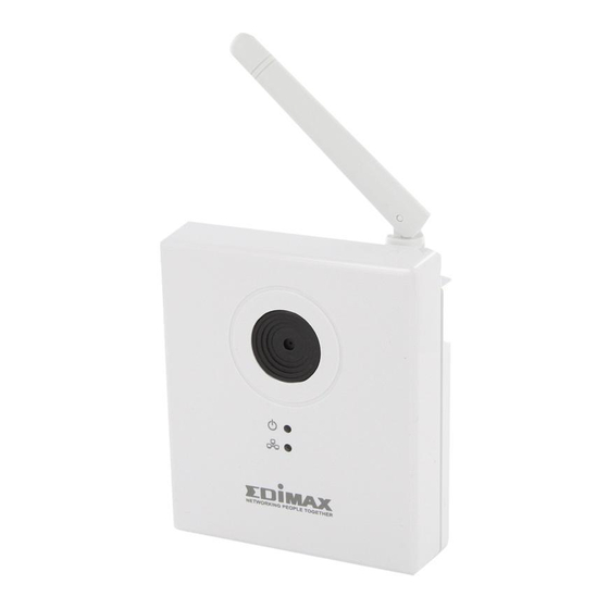
1.2 Hardware Overview Front Antenna Camera Power Lens Network Item Description When the camera is first turned on, the LED will flash while the camera connects to the cloud. When the LED remains on without flashing, the Power/Cloud LED camera has successfully connected to the cloud. This LED flashes when there is wired or wireless network activity. - Page 7 Back Mount Connector WPS/Reset button Power Adapter Ethernet Port LAN Port Item Description Attaches to the enclosed mounting kit, which allows the camera to stand or to hang from a Mount Connector wall or ceiling. Hold down the button for 2 seconds to start WPS connection mode, or hold it down for 10 seconds WPS/Reset button to reset the camera to factory default settings.
-
Page 8: Installing The Network Camera
1.3 Installing the Network Camera Please follow the following instructions to setup your new network camera. 1. Remove the camera and its accessories from the packaging. 2. Review the contents and compare with the component list. If any components are missing, please contact your supplier. 3. - Page 9 6. After installation, the Power/Cloud LED will flash for 10 to 15 seconds while the camera connects to the cloud. When the LED stops flashing, the camera has successfully connected to the cloud.
-
Page 10: Chapter Ii: Accessing The Ediview Finder Utility
Chapter II: Accessing the EdiView Finder Utility 2.1 Edimax Ediview Installation Package The network camera package includes a CD-ROM that contains the utilities and reference manuals to assist in installing, locating and using the network camera. When the CD-ROM is inserted into your computer, the following screen... -
Page 11: Installing The Ediview Finder Utility Software
2.2 Installing the Ediview Finder Utility Software 1. Click the “Setup Utility” icon to start the installation wizard. 2. Click “Next” to start the installation process. - Page 12 3. To set the application installation folder: Click “Next” to use the default value, or Click “Browse” to select a different location on your file system. 4. To set the application startup options: Select “Create a desktop icon” to add an application icon to the desktop Select “Create a Quick Launch icon”...
- Page 13 5. The application is ready to install. Review the installation settings in the information window. Click “Install” to continue or “Back” to return to the previous step. 6. The progress of the installation is displayed in the following window. This step may take several minutes to complete.
-
Page 14: Running Ediview Finder For The First Time
7. EdiView Finder is installed. Click “Launch EdiView Finder Utility” if you want to use the application after the installation is finished. Click “Finish” to close the installation window. 2.3 Running EdiView Finder for the First Time Note: Please set your wireless router or access point to use WPA2-AES encryption. - Page 15 Configure Icon 2. The utility automatically detects the cloud connection. 3. When the utility prompts to configure wireless settings, click “Yes” to set up a wireless connection.
- Page 16 4. Pick the SSID for the wireless router and enter the password. Alternatively, run WPS mode to connect to the wireless router. Please first make sure your router supports WPS. Click “Start” to begin WPS mode.
- Page 17 5. Unplug the network camera’s Ethernet cable and click “Next”. 6. When the network camera has successfully connected to your wireless router, the utility shows “Connection detected.” Click “Next” to continue.
- Page 18 7. Enter a camera name, and enter a password (twice, for confirmation) for the camera. If no password is entered, the default 1234 is used. 8. If the setup has been successful, a dialogue box is shown with a URL for remotely viewing the camera over the cloud.
-
Page 19: Locating Network Cameras On The Network
2.4 Locating Network Cameras on the Network The network camera comes with a software utility, called EdiView Finder, which locates and sets up network camera(s) on a LAN and defines a camera’s name and password. Note: To install the network camera location application, please see Installing EdiView Finder Utility Software (page 10) Note: If the EdiView Finder utility cannot locate a network camera on the LAN, the PC’s network settings may need to be reconfigured. - Page 20 Connection information for a network camera is displayed in each listing under “IP Address”. Other camera related information, such as the camera name, model, and MAC address, is also displayed here. Previewing a Network Camera Image To preview an image on a network camera: 1.
- Page 21 3. Click “OK” to open a preview window, or “Cancel” to close the login window.
-
Page 22: Chapter Iii: Configuring The Surveillance Software
Chapter III: Configuring the Surveillance Software 3.1 Configuring the EdiView Finder Utility The EdiView Finder utility provides the ability to locate and configure camera(s) on your network. Toolbar Features The EdiView Finder utility has two buttons, one to search for network cameras and one to display a camera’s configuration settings. - Page 23 Setting the Interface Language The utility software supports three languages: English, traditional Chinese, and Simplified Chinese. You can select the language to use from the language dropdown menu located in the lower right corner of EdiView Finder. Configuring a Network Camera 1.
- Page 24 3. Select “DHCP” to have the network router designate an IP address, or select “Static IP” to enter the designated IP address, subnet mask, gateway, and DNS information.
- Page 25 4. To modify additional settings, click “Advanced”. 5. Click “OK” to save the changes and exit the dialogue box.
-
Page 26: Configuring The Web-Based Management Interface
3.2 Configuring the Web-Based Management Interface 3.2.1 Installing the Web-Based Management Interface Viewing the Web-Based Management Interface The web-based configuration interface is viewable on any of the modern browsers, such as Microsoft Internet Explorer (IE) 7 or higher, Firefox 3.6 or higher, Google Chrome 10 or higher, Safari 5 or higher, or Opera 11 or higher. - Page 27 4. If the following prompt appears, click “OK”. 5. Click “Download the latest ActiveX” link to download the plugin. 6. Click “Run” to start the installation. 7. The following information prompt appears. Click “Run” to install the plugin or “Don’t Run” to cancel the installation.
- Page 28 8. Click “Next” to start the installation, and following on-screen setup wizard until the installation is complete. 9. Click “Finish” to complete the installation.
- Page 29 The management interface screen is now displayed on the browser. Press “F5” or “CTRL-R” to reload the web page if the configuration screen is not visible. Note: DirectX and system drivers may be required. Download Microsoft DirectX from http://www.microsoft.com...
-
Page 30: Basic Settings
3.2.2 Basic Settings 3.2.2.1 Network To configure network settings, Select “Network” from the menu. - Page 31 Item Description Network Type Select the type of Ethernet connection: Static IP, DHCP, and PPPoE. Please select one from dropdown menu. If you’re not sure, please consult your network administrator or ISP. Static IP: IP: Please assign an IP address to this network camera.
- Page 32 next time, it will be necessary to add a colon and port number after the camera’s IP address. For example, if the camera’s IP address is 192.168.2.3 and the HTTP port number is 82, you will need to enter ‘http://192.168.2.3:82’ into your web browser’s address bar.
- Page 33 Item Description Wireless You can enable or disable wireless Connection functionality here. Please note: You can switch wireless network off, but you can’t switch wired Ethernet off. Network Type Select the type of network you wish to connect: Currently only Infra (infrastructure: wireless access point) is available.
- Page 34 networks of same operating mode. Band Select the wireless band: 20MHz only or 20/40MHz auto switch. It’s recommended to select ‘Auto 20/40MHz’. Available The camera will list all nearby networks Networks and their parameters in this field. If the network you wish to connect to fails to appear hear, click ‘Refresh’...
- Page 35 WEP: Use WEP encryption WPA-PSK: Use WPA with PSK encryption. WPA2-PSK: Use WPA2 with PSK encryption. The authentication type you select here must be identical to the settings of the access point. Encryption Type Select the wireless encryption type. This option will vary depending on the authentication type of the network you wish to connect to.
- Page 36 This setting must be identical to the settings of the network you wish to connect to. 3.2.2.3 Dynamic DNS If your Internet service provider doesn’t issue a fixed IP address, you can use this function to report your current IP address to a dynamic DNS service provider, so you can locate your camera without having a fixed IP address.
- Page 37 3.2.2.4 Date and Time You can set up the camera’s system date and time here. Maintaining a correct date and time is essential for replaying recorded video. Item Description Mode Select date & time setup mode: Manually: Set time manually. NTP: Use NTP (Network Time Protocol) to set the date and time automatically via the network.
- Page 38 select ‘Enable’, or select ‘Disable’ if daylight saving is not used. 3.2.2.5 Users Apart from the default admin operator account, you can add additional operator accounts or user accounts here. Operator accounts can perform all functions and configurations of this camera, while guest accounts an view images only.
- Page 39 Modify Click this button to save changes to an existing user. Remove Click this button to remove a user. You must select a user in the ‘User List’ field first. Anonymous Select ‘Enable’ to enable anonymous users Login to log in to this network camera and view images.
- Page 40 Item Description Enable IGD Enable or disable the "UPnP IGD" function. The "UPnP IGD" function help you to configure the NAT in router automatically. Automation Camera will choose an external HTTP port Configuration randomly and add this port forwarding entry into the router. External HTTP An external HTTP port chosen by user.
-
Page 41: Video
3.2.2.8 Language Set the configuration system’s language here. There are ten options. 3.2.3 Video 3.2.3.1 Video Settings Here users can change video settings, such as video and frame rate settings. - Page 42 Item Description Resolution Change the video resolution from the dropdown list. Available resolutions are: SXVGA (1280 x 960) VGA (640 x 480) QVGA (320 x 240) Higher resolution provides more video detail, but requires more bandwidth. MAX. Frame rate Select the maximum video frame rate. Higher frame rate provides smoother video, but also requires more bandwidth.
-
Page 43: Events
3.2.3.2 Image Appearance Change video image appearance settings here. Item Description Brightness / Change the video’s appearance by clicking Contrast / and dragging the blue lever. Saturation / Sharpness / Reset to default Click this button to reset all settings back to default values (50). - Page 44 Item Description Motion Select ‘Enable’ to enable motion detection, Detection enable or ‘Disable’ to disable it. Motion Select the time interval this camera uses to Detection detects motion. Interval To detect minor motions, select a shorter time; to ignore minor motions, select a longer time.
- Page 45 ‘Disable’ to disable this feature. Detection Region You can set up the areas in the video where the camera will detect changes in video. Motions outside the detection region will be ignored by the camera, and the camera will do nothing when such motions occur. This helps minimize the chances of false alarms.
- Page 46 To move the motion detection region, position the mouse within the motion detection area, and drag the mouse. Sensitivity Change the sensitivity of motion detection. Set this to a higher value (right) and the camera will trigger the alarm when only small changes are detected in the video.
- Page 47 User Name Input the user name required by the FTP server. Password Input the password of the FTP server. Port Input the port number of the FTP server, this should be an integer between 1 and 65535. Please don’t change this value unless instructed by FTP server’s administrator.
- Page 48 Item Description Public Server If you’re using Hotmail, Yahoo mail, or Google mail, select the appropriate item from dropdown menu. The camera will fill in the SMTP server address and port number for you automatically. SMTP Server Input the host name or IP address of the SMTP server.
-
Page 49: System
You can click “Send a Test E-Mail” to send a test e-mail to the designated recipient address, to determine if the parameters set here are correct. 3.2.5 System Here users can configure the basic system settings, or backup/restore system configurations. 3.2.5.1 Basic Item Description... - Page 50 3.2.5.2 Advanced Item Description Firmware You can improve the functionality of this Filename camera by uploading new firmware files when available. Please download new firmware files from our website, and save it to your computer’s hard disk. Then, click the ‘Browse’...
-
Page 51: Status
back to default values, except network settings. You can still use the same IP address to connect to the IP camera. 2) Factory Default: Reset all settings, include network settings. Please reconnect to IP camera by its default IP address: 192.168.2.3 Click ‘Apply’... - Page 52 3.2.6.2 System Log The network camera’s usage and actions will be displayed here.
- Page 53 Item Description Log Level Select the log level from the dropdown list. Select 0 and the network camera will only log very important information, or select 4 to log everything. Remote Log This camera can send log information to a remote server for archiving.
-
Page 54: Configuring Myedimax.com
3.3 Configuring myedimax.com The images from the network camera can be viewed from a computer remotely, as long as Internet access is available and the camera is connected to the cloud. Note: This feature requires a web browser that supports Java applets. If Java applets are not viewable in your browser, please visit http://www.java.com download and install the Java software. - Page 55 3. When the Java applet loads, enter the camera’s password. The default password is 1234. Click “OK” to continue. 4. The camera can now be controlled from the applet.
-
Page 56: Configuring The Network Camera From Myedimax.com
3.3.2 Configuring the Network Camera from myedimax.com The network camera can be operated and configured by clicking the configuration icon on the toolbar located below the image. 1. Click to launch the configuration menu. -
Page 57: Using Myedimax.com
2. Use the slider controls to change the image brightness, saturation, sharpness, video quality, pan & tilt speed, video resolution, and language. If certain options are grayed out and unavailable, then that means they are not supported by this model network camera. 3.3.3 Using myedimax.com 1. -
Page 58: Configuring The Desktop 16-Channel Viewer
3.4 Configuring the Desktop 16-Channel Viewer An alternative to the web-based interface is the desktop 16-Channel Viewer software, which offers the ability to view multiple cameras at once. 3.4.1 Installing the 16-Channel Viewer To install the 16-Channel Viewer, insert the enclosed CD into your computer’s CD-ROM drive, and select 16-Channel Viewer when the setup screen appears. - Page 59 2. Click “Browse” to set the application installation folder, or leave the default folder unchanged if you prefer. Click “Next” to continue.
- Page 60 3. To set the application startup options, select “Create a desktop icon” to add an application icon to the desktop. Select “Create a Quick Launch icon” to add an application icon to the quick launch bar. 4. After reviewing the installation details, click “Install” to continue or “Back” to return to the previous step.
- Page 61 5. The installation process is displayed in the following window. This step may take several minutes to complete. 6. Click “Finish” to complete the installation.
-
Page 62: Using The 16-Channel Viewer
3.4.2 Using the 16-Channel Viewer You can click the “IPCam Surveillance Software” icon or link from your desktop, quick launch bar, or Start Menu to launch the 16-Channel Viewer. Note: If your computer shows a Windows Security Alert, please select “Unblock” or the viewer software will not work properly. - Page 63 Video display area Language Display layout Full screen / Scan Zoom Out / Zoom In PTZ Control / Home Message display Recording / System configure Playback / Snap shot Close window (stop surveillance) / Minimize window Item Description Video display The images from all connected cameras will area be displayed here.
- Page 64 Scan Click this button and the 16-Channel Viewer will switch through the images of all connected cameras automatically. Click this button once to activate the scan function (scan icon will turn blue ), click again to stop scanning (scan icon will turn white Zoom out Zoom-out (To see more objects).
-
Page 65: Configuring The 16-Channel Viewer
Minimize Minimizes the 16-Channel Viewer software window window. Video display Displays the images of all cameras according area to the display layout selected. 3.4.3 Configuring the 16-Channel Viewer Before you use this 16-Channel Viewer software, you must configure the camera(s) you wish to connect to. Please click the “Configure” button a popup menu will appear: Please select ‘Configure Cameras’... - Page 66 Item Description Channel Select the channel number you wish to set. Camera All cameras found on your local network will Search be displayed in the ‘Camera Search’ box. Select Select a camera listed in the ‘Camera Search’ box, and click the ‘Select’ button to fill all parameters of the selected camera into every camera configuration field.
- Page 67 After you’ve set all channels you wish to set, click ‘OK’ to save settings, and if everything’s correct, you’ll see the camera’s image in the 16-Channel Viewer software’s main display area: 3.4.3.2 Scheduled Recording In this tab, you can setup scheduled video recording, so you can record the video captured by all cameras you have according to a pre-defined schedule.
- Page 68 Item Description Channel Select the channel number you wish to set. One Time You can specify a one-time schedule for the selected Schedules camera; this schedule will be executed once only. Click this button and a new window will appear: (One Time Schedules) Please specify the time duration of this one-time...
- Page 69 You can define a recording schedule that will be executed at the specified time of certain day(s) in the week. Please check all days that apply, and set the start time in the ‘From’ field. You can set the duration of the video recording in the ‘Period’ field (format is HH:MM:SS), and the end time will be calculated automatically and displayed in the ‘To’...
- Page 70 3.4.3.3 Audio For cameras that support audio, you can use this tab to decide if you wish to hear the audio captured by the selected camera. Item Description Channel Select the channel number you wish to set. Mute Audio Check this box and the 16-Channel Viewer software will not play the audio captured by this camera.
- Page 71 3.4.3.4 Motion-Triggered Recording With this function activated, only motions captured by the camera will be recorded, so you don’t have to waste hard disk storage space on images you don’t need to pay attention to. WARNING: For applications where security is of high priority, it’s not recommended to use this function since some small but significant changes you may need to know about may not be sufficient to trigger the camera and the camera will not start recording.
- Page 72 when motion motion has been detected by the camera. is triggered Save settings in this tab. Cancel Discard all settings in this tab.
-
Page 73: General Options
3.4.4 General Options You can set system-wide settings for the 16-Channel Viewer software in this menu. 3.4.4.1 General All general settings such as file storage directory and recording spaces can be set here. - Page 74 Item Description Data Set the directory (folder) you wish to store the Directory recorded video and captured image. You can click ‘Browse’ button to pick a directory in your hard disk. Free Displays remaining storage space. Recording Space Max Video Defines the maximum file size of every video File Size file.
- Page 75 3.4.4.2 Email Setting If you want to use motion detection function and wish to get an email that contains the image captured by the camera, please setup your email related parameters here first. Item Description E-Mail Subject Specify the subject of sending email. Recipient Here lists all email addresses you set.
- Page 76 Click this button and you’ll be prompted to input the email address. Click ‘OK’ to save changes. Edit Select an email address from ‘Recipient E-Mail Address’ box, and click ‘Edit’ to edit the email address. Delete Delete selected email address. Sender E-Mail Specify the email address of email sender.
- Page 77 your email software or ask your ISP / network administrator if you’re not sure about this. SMTP Input the SMTP password of your SMTP server Password here. In most cases, it’s the same with your POP3 password (the one you used to receive email).
- Page 78 Here are the descriptions of all setting items: Item Description Enable Requires password authentication when this software starts. Disable Password authentication is not required when this software starts. Password Input the password you wish to use here. Confirm Input the password you wish to use here Password again.
- Page 79 3.4.4.4 About This tab shows the version number of the 16-Channel Viewer software you’re using.
-
Page 80: Changing The Display Layout
3.4.5 Changing the Display Layout This 16-Channel Viewer software provides 8 display layouts: Every layout displays a different number of cameras and camera arrangements, you can click the icon that presents a specific kind of layout, and the video display area will change accordingly. Layout style Displays the video of 1 camera only. - Page 81 Layout style Displays the video of up to 6 cameras. 3: 6 Cameras Layout style Displays the video of up to 8 cameras. 4: 8 Cameras Layout style Displays the video of up to 9 cameras. 5: 9 Cameras Layout style Displays the video of up to 10 cameras.
- Page 82 Layout style Displays the video of up to 13 cameras. 7: 13 Cameras Layout style Displays the video of up to 16 cameras. 8: 16 Cameras...
-
Page 83: Full-Screen Mode
3.4.6 Full-Screen Mode If you want to use all available space on your monitor to display surveillance images, you can click the ‘Full Screen’ button to switch the display mode to full-screen mode. To exit full-screen mode, press the ‘ESC’ key. -
Page 84: Scan
3.4.7 Scan If you have more than one camera configured, and you wish to switch the displaying image between cameras, you can click ‘Scan’ button to switch between all configured cameras. NOTE: If a camera is configured but disconnected, it will still be displayed in a scan sequence (you’ll see nothing and you’ll see ‘Disconnected’... -
Page 85: Zoom-In/Zoom-Out
3.4.8 Zoom-in/Zoom-out For cameras that support the zoom-in / zoom-out function, you can use this function to see more objects that fall in the scope of camera’s view, or enlarge the image size of a certain object to see its detail. Please select a camera in video display area by clicking on its image, then click button to see more objects that fall in the scope of camera’s view, or click to enlarge the image size of a certain object to see its detail (Before zoom-in,... -
Page 86: Ptz
3.4.9 PTZ For cameras that support pan - tilt functions, you can change the position that camera points to, to see different places that fall in the scope of camera’s view. Please select a camera in video display area by clicking on its image, and then click the directions you wish the camera to move to (total 8 directions available). -
Page 87: Snapshot
3.4.10 Snapshot You can take a snapshot of selected camera and save it to ‘Snapshot’ sub-folder of pre-defined data directory. Click snapshot button once to take a snapshot; you can take as much snapshot as you want before hard disk is full. -
Page 88: Recording
3.4.11 Recording You can start video recording of selected camera manually by clicking ‘Start Recording’ button: When recording starts, you’ll see a message displayed in message displaying box like ‘1/1 10:00:00, Camera 2 Start Manual’, which means camera 1 starts recording manually on 1/1 at 10:00:00. -
Page 89: Video Playback
3.4.12 Video Playback You can playback all recorded video by clicking this button. A new window will appear: You have to search the video file before you can play it. There are two kinds of video search: Time Search (search all videos file that falls in a specific period of time) and Motion Search (search all videos recorded by motion detection function and falls in a specific period of time). -
Page 90: Configuring The Android Surveillance Software
3.5 Configuring the Android Surveillance Software 3.5.1 Installing the Android Surveillance Software 1. Launch the Android Market. 2. Tap the magnifier icon at the upper-right corner of the Android market and enter “ediview” into the search field. - Page 91 3. Tap “ediview” to download and install the app. 4. At the installation confirmation screen, tap “Install” to start installation or “Cancel” to exit. The installation may take several minutes, depending on connection speed.
-
Page 92: Adding Network Cameras
Automatically scan and add available cameras locate on the network, or Manually enter a network camera’s information Automatically Adding a Camera 1. When the EdiView application is launched, it automatically searches the LAN for all Edimax network cameras. - Page 93 2. If a camera is found, it is shown in the camera list.
- Page 94 3. If no camera is found, tap “OK” to close the information dialogue. 4. Tap “Manually” to manually add a new network camera.
- Page 95 Manually Adding a Network Camera on a LAN in IP Mode Note: cameras added in IP mode can only be accessed on the local network. 1. Tap the “Cloud/IP Mode” button to set the mode to “IP”. 2. Enter information into the following fields: Parameter Description Camera Name...
- Page 96 Manually Adding a Network Camera on the Cloud in Cloud Mode 1. Tap the “Cloud/IP Mode” button to set the mode to “Cloud”. 2. Enter information into the following fields: Parameter Description Camera Name Define a name for the camera that is shown in the camera list.
-
Page 97: Android Surveillance Software Configuration Options
3.5.3 Android Surveillance Software Configuration Options Tap a camera’s icon in the list to edit the configuration settings. Configuring Network Settings on a LAN in IP Mode 1. Tap the text box of a parameter and enter new information to change the configuration settings. - Page 98 Parameter Description Camera Name Define a name for the camera that is shown in the camera list. IP Address / DDNS Enter the IP address of the host name of the network camera. Port Enter the port number of the camera. Username Enter the username of the network camera.
- Page 99 Parameter Description Camera Name Define a name for the camera that is shown in the camera list. Cloud ID Enter the Cloud ID of the network camera. The Cloud ID is a twelve character alphanumeric value of the network camera, found on the included Cloud ID card. Username Enter the username of the network camera.
- Page 100 2. Drag the slider bars right or left to configure brightness, saturation, sharpness, video quality, and pan/tilt speed. 3. Tap “Done” to save the changes. Tap “Cancel” to discard the changes. Removing a Network Camera from the List To remove a network camera from the list: 1.
-
Page 101: Using The Android Surveillance Software
3.6 Using the Android Surveillance Software 3.6.1 Software Overview Main Menu Buttons To show the EdiView menu buttons, press the menu button on the Android device. The EdiView menu buttons perform the following functions: View live images of the network cameras Use Google Maps to locate network cameras Add a new network camera to the camera list Reload the network camera list... -
Page 102: Viewing The Camera List
Show information about the EdiView application 3.6.2 Viewing the Camera List Viewing a Live View If the network camera is connected, you’ll see a picture appear. Tap the picture to view the live image. To configure the network camera’s parameters, tap the icon. - Page 103 Viewing Multiple Cameras If you have more than one network camera, tap the icon to see the images of up to four network cameras at the same time. Tap a camera’s image to enlarge it. Tap the button to see up to twelve network cameras at the same time.
- Page 104 All events are displayed along with the time when the event was triggered. Tap on the event to see an enlarged picture. The image of the event is displayed along with the time it was triggered.
- Page 105 To save a snapshot of this event, tap the button. The message “Event image saved” indicates that the image has been saved successfully.
-
Page 106: Mapping A Camera
3.6.3 Mapping a Camera The mapping feature can be used to mark the location of the network camera on Google Maps. An active Internet connection is required to show the map on the Android device. Tap the “Map” button at the bottom of the device to access the map menu. Google Maps is shown on the Android device. - Page 107 When you find the location where a network camera is installed, press the “Menu” button on your Android device and tap “Locate”. A camera list is shown. Select the network camera you wish to mark on the map.
-
Page 108: Refreshing The Camera List
3.6.4 Refreshing the Camera List If new cameras are added or removed from the network, scan the network again to update your camera list. To update the cameras displayed in the camera list, tap “Refresh”. -
Page 109: Configuring The Ios Surveillance Software
3.7 Configuring the iOS Surveillance Software 3.7.1 Installing the iOS Surveillance Software 1. Tap “Edimax Ediview” to download and install the application. 2. When the application is successfully installed, the EdiView icon is shown on the screen. Launch EdiView by tapping the EdiView icon. -
Page 110: Adding Network Cameras
Manually enter a network camera’s information Automatically Adding a Camera 1. When the EdiView application is launched, it automatically searches the LAN for all Edimax network cameras. 2. If a camera is found, it is shown in the camera list. - Page 111 3. If no camera is found, an empty list is shown. Tap “Add New Camera” to manually add a new network camera. Manually Adding a Network Camera on a LAN in IP Mode Note: Cameras added in IP mode can only be accessed on the local network. 1.
- Page 112 Manually Adding a Network Camera on the Cloud in Cloud Mode 1. Tap the “Cloud/IP Mode” button to set the mode to “Cloud”. 2. Enter information into the following fields: Parameter Description Camera Name Define a name for the camera that is shown in the camera list.
-
Page 113: Ios Surveillance Software Configuration Options
3.7.3 iOS Surveillance Software Configuration Options Tap a camera in the list to edit the configuration settings. Configuring Network Settings on a LAN in IP Mode 1. Tap the text box of a parameter and enter new information to change the configuration settings. - Page 114 Parameter Description Camera Name Define a name for the camera that is shown in the camera list. IP Address Enter the IP address of a network camera. Port Enter the port number of the camera. Username Enter the username of the network camera. The default value is admin.
- Page 115 Username Enter the username of the network camera. The default value is admin. Password Enter the password of the network camera. The default value is 1234. 2. Tap “Done” to save the changes. Configuring video Display Parameters 1. Tap the parameter and enter the new information to change the video display configuration settings.
- Page 116 Note: Use a lower video quality when network bandwidth is low. 2. Tap “Done” to save the changes. Tap “Cancel” to discard the changes. Removing a Network Camera from the List To remove a network camera from the list: 1. Tap “Edit”. 2.
-
Page 117: Using The Ios Surveillance Software
3. Tap “Delete” to remove the network camera from the list. 3.8 Using the iOS Surveillance Software 3.8.1 Software Overview Main Menu Buttons To show the EdiView menu buttons, press the menu button on the iOS device. The EdiView menu buttons perform the following functions: View live images of the network cameras View a list of events, or movements, for a network camera Use Google Maps to locate a network camera... -
Page 118: Viewing The Camera List
Show a list of available network cameras, or add a new network camera to the list. Show information about the EdiView application 3.8.2 Viewing the Camera List Viewing Multiple Camera Live Views Tap the button on the upper left corner of the screen to cycle between one, four, and twelve camera live views. -
Page 119: Viewing Camera Events
3.8.3 Viewing Camera Events Viewing an Event Image To view events, which are motions detected by the network camera, tap the “Events” button. Select a network camera to show an event list. -
Page 120: Mapping A Camera
Tap an event to see an enlarged image. 3.8.4 Mapping a Camera The mapping feature can be used to mark the location of the network camera on Google Maps. An active Internet connection is required to show the map on the iOS device. - Page 121 Google Maps is shown on the iOS device. It attempts to locate the current location of the camera by GPS and the network. Note: Using the iOS device indoors may hinder the service’s ability to find the device location. To manually find the device’s location, drag a finger over the map in a direction until the desired location is found.
-
Page 122: Troubleshooting
Appendix A Troubleshooting Please don’t panic when you found this IP Camera is not working properly. Before you send this IP Camera back to us, you can do some simple checks to save your time: Problem description Possible solution(s) Can’t connect to IP Camera 1) Please check the IP address of IP Camera again. 2) Please make sure the network cable is correctly connected to your local area network. -
Page 123: Appendix B
Appendix B This IP camera’s default IP address is 192.168.2.3, and you must use a computer that uses 192.168.2.x IP address to connect to it. Please follow the following instructions to setup your computer’s IP address: 1. Please click ‘Start’ button and then click ‘Control Panel’. 2. - Page 124 3. If you didn’t see ‘Network and Internet’ in control panel, please look for ‘Network and Sharing Center’ icon and double-click it. 4. Click ‘Local Area Connection’ 5. Click ‘Properties’ 6. Click ‘Internet Protocol Version 4 (TCP/IPv4), and then click ‘Properties’...
- Page 125 7. Click ‘Use the following IP address’, and then input ‘192.168.2.1’ in ‘IP address’ and ‘255.255.255.0’ in Subnet mask’, just like shown on the left. Click ‘OK’ when finish, and close all open windows you opened...
-
Page 126: Federal Communication Commission Interference Statement
Federal Communication Commission Interference Statement This equipment has been tested and found to comply with the limits for a Class B digital device, pursuant to Part 15 of FCC Rules. These limits are designed to provide reasonable protection against harmful interference in a residential installation. -
Page 127: Declaration Of Conformity
Declaration of Conformity We, Edimax Technology Co., Ltd., declare under our sole responsibility, that the equipment described below complies with the requirements of the European R&TTE directive (2006/95/EC). Equipment : 1.3Mpx Wireless Network Camera Model No. : IC-3115W Report No. :... - Page 128 Notice According to GNU General Public License Version 2 This product includes software that is subject to the GNU General Public License version 2. The program is free software and distributed without any warranty of the author. We offer, valid for at least three years, to give you, for a charge no more than the costs of physically performing source distribution, a complete machine-readable copy of the corresponding source code.
- Page 129 intact all the notices that refer to this License and to the absence of any warranty; and give any other recipients of the Program a copy of this License along with the Program. You may charge a fee for the physical act of transferring a copy, and you may at your option offer warranty protection in exchange for a fee.
- Page 130 6. Each time you redistribute the Program (or any work based on the Program), the recipient automatically receives a license from the original licensor to copy, distribute or modify the Program subject to these terms and conditions. You may not impose any further restrictions on the recipients’...
Need help?
Do you have a question about the IC-3115W and is the answer not in the manual?
Questions and answers