
Related Manuals for Kramer VP-727


Summary of Contents for Kramer VP-727
- Page 1 Kramer Electronics, Ltd. USER MANUAL Model: VP-727 Universal Presentation Matrix Switcher / Scaler...
-
Page 2: Table Of Contents
Contents Introduction About the VP-727 Getting Started Quick Start Overview Your VP-727 Universal Presentation Matrix Switcher / Scaler Installing on a Rack Connecting the VP-727 Connecting the VP-727 Control Ports Connecting a PC (via RS-232) Connecting via RS-485 Connecting the VP-727 via the ETHERNET port... - Page 3 VP-727 Communication Protocol VP-727 Text Overlay Protocol Figures Figure 1: VP-727 Universal Presentation Matrix Switcher / Scaler Front Panel Figure 2: VP-727 Universal Presentation Matrix Switcher / Scaler Rear Panel Figure 3: Connecting the VP-727 Figure 4: Connecting the INPUTS (an example)
- Page 4 Contents Tables Table 1: Front Panel VP-727 Universal Presentation Matrix Switcher / Scaler Features Table 2: Rear Panel VP-727 Universal Presentation Matrix Switcher / Scaler Features Table 3: Crossover Cable RJ-45 PINOUT Table 4: Straight-through Cable RJ-45 PINOUT Table 5: Features and Functions of the TextOverlay Application...
-
Page 5: Introduction
2 We recommend that you use only the power cord that is supplied with the machine 3 Download up-to-date Kramer user manuals from the Internet at this URL: http://www.kramerelectronics.com 4 The complete list of Kramer cables is on our Web site at http://www.kramerelectronics.com... -
Page 6: Quick Start
Getting Started 2.1 Quick Start This quick start chart summarizes the basic steps when connecting a VP-727: KRAMER: SIMPLE CREATIVE TECHNOLOGY... -
Page 7: Overview
Overview Overview The VP-727 Universal Presentation Matrix Switcher / Scaler is a true multi-standard video to graphics scaler and presentation switcher for a wide variety of presentation and multimedia applications. It consists of a very high quality scaler with many user-selectable pixel-rates including VGA (640x480),... - Page 8 Is specifically designed to improve video quality by reducing chroma noise Comes in a rugged, professional 19" 3U rack-mountable metal enclosure Uses a universal 100-240VAC automatic power supply Control the VP-727 via the: Front panel user-friendly menu-driven OSD (see section 9.1) High contrast LCD Display (see section 9.2) IR remote control transmitter (see section 9.3)
-
Page 9: Your Vp-727 Universal Presentation Matrix Switcher / Scaler
(often associated with low quality cables) Avoiding interference from neighboring electrical appliances, making sure not to block the ventilation holes, and positioning your VP-727 away from moisture, excessive sunlight and dust Your VP-727 Universal Presentation Matrix Switcher /... -
Page 10: Figure 1: Vp-727 Universal Presentation Matrix Switcher / Scaler Front Panel
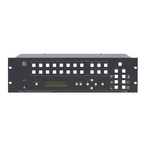
Your VP-727 Universal Presentation Matrix Switcher / Scaler Figure 1: VP-727 Universal Presentation Matrix Switcher / Scaler Front Panel KRAMER: SIMPLE CREATIVE TECHNOLOGY... -
Page 11: Table 1: Front Panel Vp-727 Universal Presentation Matrix Switcher / Scaler Features
Your VP-727 Universal Presentation Matrix Switcher / Scaler Table 1: Front Panel VP-727 Universal Presentation Matrix Switcher / Scaler Features Feature Function POWER Switch Illuminated switch for turning the unit ON or OFF IR Receiver / LED Green when the unit will accept IR remote commands; red in standby mode... -
Page 12: Figure 2: Vp-727 Universal Presentation Matrix Switcher / Scaler Rear Panel
Your VP-727 Universal Presentation Matrix Switcher / Scaler Figure 2: VP-727 Universal Presentation Matrix Switcher / Scaler Rear Panel KRAMER: SIMPLE CREATIVE TECHNOLOGY... -
Page 13: Table 2: Rear Panel Vp-727 Universal Presentation Matrix Switcher / Scaler Features
Your VP-727 Universal Presentation Matrix Switcher / Scaler Table 2: Rear Panel VP-727 Universal Presentation Matrix Switcher / Scaler Features Feature Function BNC Connector G/Y BNC Connector Connects to the PROGRAM display device (component video BNC Connector RGB or RGBHV acceptor) -
Page 14: Installing On A Rack
The machine is earthed (grounded) in a reliable way and If you are using a Kramer rack is connected only to an electricity socket with grounding. adapter kit (for a machine that is not Pay particular attention to supply connections other than 19"), see the Rack Adapters user... -
Page 15: Connecting The Vp-727
Connecting the VP-727 Connecting the VP-727 The VP-727 is a universal presentation matrix switcher / scaler, letting you choose what sources to connect to the inputs. For example, you can connect just 3 sources: an RGBHV source, an HDTV source and an RGBS source (as the... -
Page 16: Figure 4: Connecting The Inputs (An Example)
Figure 4: Connecting the INPUTS (an example) 1 As this particular example describes. As the VP-727 is universal, you can connect any type (format) of video to the inputs 2 Switch OFF the power on each device before connecting it to your VP-727. After connecting your VP-727, switch on its... -
Page 17: Figure 5: Connecting The Preview Out / Program Out Connectors
4. Connect the power cord 5. Connect a PC via RS-232 (optional), see section 7.1. 6. Connect the Kramer VP-727T Presentation Switcher Control Panel via the RS-485 port (optional), see section 7.2. 7. Connect the ETHERNET port (optional), see section 7.3. -
Page 18: Connecting The Vp-727 Control Ports
CONTROL port, see section 7.4 7.1 Connecting a PC (via RS-232) You can connect a PC (or other controller) to the VP-727 via the RS-232 port for remote control, and for upgrading the firmware. To connect a PC to a VP-727 unit, using the Null-modem adapter provided... -
Page 19: Connecting Via Rs-485
7.3 Connecting the VP-727 via the ETHERNET port To connect the VP-727 via the ETHERNET port, do the following: Connect the ETHERNET port of the VP-727 to the LAN port of your PC, via a crossover cable with RJ-45 connectors, as Table 3 and Figure 7 define... -
Page 20: Connecting The Vp-727 Via The Control Connector
Green / White Blue Blue Blue / White Blue / White Green Green Brown / White Brown / White Brown Brown 7.4 Connecting the VP-727 via the CONTROL Connector The CONTROL MiniDin 6F is reserved for future use. KRAMER: SIMPLE CREATIVE TECHNOLOGY... -
Page 21: Understanding The Vp-727
RGB/YUV, RGBS, RGsB, or RGBHV. The VP-727 is a universal presentation matrix switcher / scaler: you choose what type of source to connect to each input. You can connect different video types or the same or similar video types. See the examples in Figure 3 and Figure 4 in section 6. -
Page 22: Figure 8: Example Showing The Use Of The Preview And Program Output
Understanding the VP-727 . In this example an RGBS source is connected to input 2, and an HD Component source is connected to input 3. Set the OSD Settings as follows The PROGRAM INPUT button 3 and the PREVIEW INPUT button 2 illuminate: . -
Page 23: Switching/Scaling Of An Input
Understanding the VP-727 8.3 Switching/Scaling of an Input The VP-727 scales the selected sources to DVI, RGBHV or YUV and VGA simultaneously. It switches seamlessly between sources using the selected special effects, which include cuts, fades, and wipes. Select the appropriate source (from channel 1 to 8) via the Input command in both the Preview Setting OSD screen and/or the Program Setting OSD screen (see section 9.1.1), via the... -
Page 24: Pip Characteristics
8.5 Locking and Unlocking the Front Panel To prevent changing the settings accidentally or tampering with the unit via the front panel buttons, lock your VP-727. Unlocking releases the protection mechanism. When the front panel is locked, control is still available via RS-232, the ETHERNET, and/or the CONTROL connector. -
Page 25: Using Text Overlay
8.6 Using Text Overlay The text overlay feature is accessed via the Application Program (AP) Running this AP with the PC connected to the VP-727 lets you display text over the screen, with a rich feature set including text color and speed, transparency, text position and repetition. -
Page 26: Table 5: Features And Functions Of The Textoverlay Application
When selected, set the IP Address and Port to connect via Ethernet RS-232 Check box When selected, set the COM port and Baud Rate (115200 for VP-727) to connect via the RS-232 connector Select VP725 when connected to a VP-725 series machine... -
Page 27: Downloading The Textoverlay Program
Understanding the VP-727 Table 6: Number of Buffers, Output Resolution and Maximum Display Height Maximum Display Height According to Number of Buffers Output Resolution 640x480 800x600 832x624 852x480 1024x768 1280x720 1280x768 1280x1024 1366x768 1365x1024 1400x1050 1600x1200 480P 576P 720P 1080i 1080p 8.6.1... -
Page 28: Connecting And Disconnecting The Textoverlay Program
To connect the TextOverlay program, do the following: 1. Open the TextOverlay program. The TextOverlay application screen appears 2. Select the VP-727 check box. 3. Select the type of connection to be used When selecting RS-232, in the COM port box select the COM port you... -
Page 29: Saving And Loading Settings
Understanding the VP-727 5. If required, type the text in the message box, and edit the text message (see section 8.6.2). 6. Press the green “ Start to run Text Overlay” button. The green button changes to a yellow “ Stop Text Overlay” button. -
Page 30: Operating The Vp-727
The OSD superimposes a menu on the Preview screen from which you can control your VP-727. When the OSD front panel button is on, pressing the MENU button on the front panel or the Menu key on the infra-red remote control transmitter displays the first OSD screen , the “... -
Page 31: Table 8: Preview And Program Setting Osd Menus
Operating the VP-727 Table 8: Preview and Program Setting OSD Menus Level 1 Level 2 Level 3 Range Default Input Source Channel 1 to 8 (selects the input source) Type RGBHV, RGBS (PC/Video), RGsB (PC/Video), HD Component, SD Component, Y/C or CV (selects the input signal type) Video Standard Auto, NTSC, PAL, PAL-M, PAL Comb.-N, NTSC 4.43,... -
Page 32: Preview / Program Setting Output Test Pattern Screens
Operating the VP-727 9.1.1.1 Preview / Program Setting Output Test Pattern Screens Figure 12 illustrates the Test Pattern screens 32 Gray Ramp Sharpness Green Blue White Black Chessboard Color Bar Aspect Ratio RGB Gray Ramp Gamma Check Figure 12: Test Pattern Screens... -
Page 33: Preview / Program User Mode Output Setting
Operating the VP-727 9.1.1.2 Preview / Program User Mode Output Setting Figure 13 and Table 9 define the parameters of the User Mode Setting Figure 13: User Mode Setting Table 9: User Mode Setting Definitions User Mode Setting Definitions HT: Horizontal total... -
Page 34: Transition Commands
Operating the VP-727 9.1.2 Transition Commands Figure 14 illustrates the Transition screen: Figure 14: Transition OSD Set the transition direction via the Transition Effect Option, as Table 10 defines: Table 10: Transition Effect Option Commands Level Level 2 Level 3... -
Page 35: Utility Commands
Operating the VP-727 9.1.3 Utility Commands Figure 15 and Table 11 define the Utility screen: Table 11: Utility OSD Setting Level 1 Level 2 Level 3 / Range TCP/IP Setting DHCP On/Off (see section IP Address 9.1.3.1) Subnet Mask Gateway... -
Page 36: Misc Setting Commands
Lock, Background and Blank Color commands. 9.1.3.2.1 Logo You can set the Kramer logo On or Off. When set to On (the default), it is displayed for 20 seconds upon initialization. If set to Off, it is disabled. 9.1.3.2.2 Save Lock The Save Lock complements the Panel Lock . -
Page 37: Save/Recall/Erase Setting Commands
For example, to set the time out to 60 seconds via the LCD Display, using the front panel buttons, do the following: 1. Turn the VP-727 unit ON, and press the OSD ON button (if selected). 2. Press the appropriate front panel OSD buttons (as defined in Figure 18). -
Page 38: Operating Via The Infra-Red Remote Control Transmitter
Operating the VP-727 9.3 Operating via the Infra-red Remote Control Transmitter You can control the VP-727 remotely, from the infra-red remote control transmitter (that has a range of up to 15 meters and is powered by two AAA size 1.5V DC batteries), as defined in Figure 19 and Table 13:... -
Page 39: Operating Via Ethernet
Figure 20: VP727 Ethernet Application Main Dialog Box (Configuration Tab) 1 Or connect the serial port of your VP-727 to the serial port of your PC (see section 7.1) 2 Or download the software from our Web site on http://www.kramerelectronics.com... -
Page 40: Figure 21: Vp727 Control Application Search Panel Screen
Operating the VP-727 Table 14: VP727 Ethernet Application Configuration Tab Button Function Autoscan Press to automatically scan for connected machines Press to scroll down the Server list Down Press to scroll up the Server list Delete Press to delete an IP number... -
Page 41: Control The Vp-727 Via The Ethernet/Serial Port
Figure 23: Setting an IP Number 9.4.3 Control the VP-727 via the Ethernet/Serial Port To control the VP-727 via the Ethernet, do the following: 1. On the VP727 Control Application screen, click the Control tab. The Control screen appears (see Figure 24). -
Page 42: Operating Via The Control Connector
9.5 Operating via the CONTROL Connector Not available at the time of printing 9.6 Operating via RS-232 You can control the VP-727 via the RS-232 port using the Kramer VP-727 Control Application (see section 9.4.3). 1 Go to our Web site: http://www.kramerelectronics.com... -
Page 43: Technical Specifications
10 Technical Specifications Table 15 includes the technical specifications: Table 15: Technical Specifications of the VP-727 INPUTS: 8 sets of universal BNC connectors: R/Pr, G/Y/CV, B/Pb/C, Hs/Cs, and Vs, each programmable for use as CV, YC, RGB, YCbCr, YPbPr, RGBS or RGBHV... -
Page 44: Vp-727 Communication Protocol
VP-727 Communication Protocol 11 VP-727 Communication Protocol This addendum includes the Communication Protocol for the VP-727: Set and Get command: Set Command: Y Control_Type Function Param 1 ..Param N CR Reply: Z Control_Type Function Param 1 ..Param N CRDoneCR... -
Page 45: Table 16: Set Commands
VP-727 Communication Protocol Table 16: Set Commands Control Type Param1 Function Description Power Panel Lock Take Fade Diagonal Wipe Circle Square Corner Chessboard Preview Picture Preview Freeze Preview Blank Preview PIP Program Picture Program Freeze Program Blank Program PIP Down... - Page 46 VP-727 Communication Protocol Control Type Param1 Function Description Preview Calibration H-Position Preview Calibration V-Position -32 ~ 32 Preview Calibration Saturation -50 ~ 50 Preview Calibration Frequency 0 ~ 31 Preview Calibration Phase Preview Calibration Auto Gain Preview Calibration Auto Image...
- Page 47 VP-727 Communication Protocol Control Type Param1 Function Description 6 ~ 200 Preview Output User Mode OCLK 0 ~ 255 Preview Output User Mode Delay Preview Output User Mode SetCurrent 0: Channel 1; 1: Channel 2; 2: Channel 3; 3: Channel 4; 4: Program Input Source Channel 5;...
- Page 48 VP-727 Communication Protocol Control Type Param1 Function Description 0: Off; 1: 32 Gray Ramp; 2: Sharpness; 3: Red; 4: Green; 5: Blue; 6: White; 7: Black; 8: Chessboard; 9: Color Bar; 10: Program Output Test Pattern Aspect Ratio; 11: RGB Gray Steps; 12: Gamma Check...
- Page 49 VP-727 Communication Protocol Control Type Param1 Function Description 180 - Recall Setting 6 181 - Recall Setting 7 182 - Recall Setting 8 183 0: Cancel; 1: Ok Factory Reset 184 - Preview Main Standard 185 - Preview PIP Type...
-
Page 50: Vp-727 Text Overlay Protocol
VP-727 Text Overlay Protocol 12 VP-727 Text Overlay Protocol Table 17 includes the Text Overlay Protocol. Each command includes three parameters: P1, P2 and P3. Table 17: Text Overlay Protocol of the VP-727 Functions Command Comments Display Buffer T12ED ** ** Page No. - Page 51 EXCLUSION OF DAMAGES The liability of Kramer for any effective products is limited to the repair or replacement of the product at our option. Kramer shall not be liable for: Damage to other property caused by defects in this product, damages based upon inconvenience, loss of use of the product, loss of time, commercial loss;...
- Page 52 For the latest information on our products and a list of Kramer distributors, visit our Web site: www.kramerelectronics.com, where updates to this user manual may be found. We welcome your questions, comments and feedback. Safety Warning: Disconnect the unit from the power supply before opening/servicing.
Need help?
Do you have a question about the VP-727 and is the answer not in the manual?
Questions and answers