Powerware 9170 User Manual
3kva-18kva, 50 and 60 hz
Hide thumbs
Also See for 9170:
- Product catalog (24 pages) ,
- User manual (94 pages) ,
- User manual (118 pages)
Table of Contents
Advertisement
Quick Links
Download this manual
See also:
User Manual
Advertisement
Table of Contents

Related Manuals for Powerware 9170


Summary of Contents for Powerware 9170
- Page 1 02/20/2001 ® Powerware 9170 User’s Guide 3 kVA – 18 kVA, 50 and 60 Hz www.powerware.com...
- Page 2 CheckUPS II is a registered trademark and BestLink and BestDock are trademarks of Best Power. Windows is a registered trademark of Microsoft Corporation. Copyright 2000–2001 Powerware, Raleigh, NC, USA. All rights reserved. No part of this document may be reproduced in any way without the express written approval of Powerware.
-
Page 3: Table Of Contents
........... . . Powerware 9170 User’s Guide www.powerware.com... - Page 4 ........... . Reading the Powerware 9170 System Logs .
-
Page 5: Introduction
C H A P T E R NTRODUCTION The Powerware 9170 uninterruptible power system (UPS) is a modular UPS that contains battery modules and power control modules (referred to as power modules). These modules plug into a rack cabinet structure containing additional control, communication, and display functions that enable integrated control of all power modules. -
Page 6: Safety Warnings
127/127 for 220 Vac. DO NOT mix the two types of power modules in the same Powerware 9170 cabinet. Battery modules to be used in the Powerware 9170 system are model ASY-0529. Each battery module weighs 30 lb (14 kg). Use care in lifting and moving battery modules. -
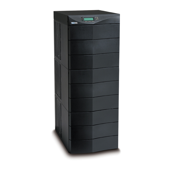
Page 7: Physical Features
Introduction Physical Features The Powerware 9170 UPS is available in four cabinet sizes. Figure 1 through Figure 6 show the 3-slot and 9-slot configurations and identify basic Powerware 9170 system features. Six-slot and 12-slot cabinets are also available; external battery cabinets are available in 6-, 9-, and 12-slot sizes. - Page 8 Introduction Front Panel Display Front Cover Bezels Cabinet Base Figure 3. Nine-Slot Cabinet (Front View) Powerware 9170 User’s Guide www.powerware.com ®...
- Page 9 (optional) Input Power Cable (optional) Figure 4. Nine-Slot Cabinet (Rear View) Handle/Latch Handle Release Thumbscrew Insertion/Extraction Cams Figure 5. Power Module (ASY-0528 and ASY-0567) Secondary Stop Release Latch Release Figure 6. Battery Module (ASY-0529) Powerware 9170 User’s Guide www.powerware.com ®...
- Page 10 Introduction Powerware 9170 User’s Guide www.powerware.com ®...
-
Page 11: Installation Setup
C H A P T E R NSTALLATION ETUP This chapter explains how to setup and install the Powerware 9170 cabinets: Unpacking and setup, including clearances and location requirements Caster cart installation Stabilizer bracket installation (for 12-slot cabinets with non-isolated... -
Page 12: Location Requirements
Power and battery modules are shipped in separate boxes on another pallet. Three-slot cabinets and modules are shipped on one pallet. NOTE Verify that all Powerware 9170 UPS power modules are the proper type for the UPS cabinet: Universal (single-phase) modules have white labels; split-phase modules have blue labels. -
Page 13: Nine- And Twelve-Slot Cabinets
Installation” on page 23 for hardwired units. Nine- and Twelve-Slot Cabinets NOTE The 12-slot Powerware 9170 UPS cabinet with non-isolated output is shipped with two stabilizer brackets. These brackets must be attached to the wall or the floor behind the UPS cabinet (see page 11). -
Page 14: Caster Cart Installation
Figure 7. Three-Slot Cabinet Being Lowered onto Caster Cart The caster cart, shipped separately from the UPS cabinet, must be placed under the cabinet before installing power and battery modules, and before plugging the UPS into the intended power outlet. Powerware 9170 User’s Guide www.powerware.com ®... -
Page 15: Stabilizer Bracket Installation
Stabilizer Bracket Installation The 12-slot Powerware 9170 UPS cabinet with non-isolated output is shipped with two stabilizer brackets. These brackets must be attached to the wall or the floor behind the UPS cabinet. Under all module-loading conditions, they act as a protective stop to prevent the cabinet from falling forward if it is unintentionally pushed away from the wall. -
Page 16: Rack-Mount Installation
Step 1. Position the cover lip to fit behind the front display panel. 4. Install three metal clip-nuts onto each side flange (6 clip-nuts on 6-slot cabinets) along the front of the UPS cabinet (see Figure 9). Powerware 9170 User’s Guide www.powerware.com ®... - Page 17 7. Install one equipment rail on each side of the rack using four 10-32 flat-head screws per rail. Select the proper holes in the rail that position the UPS at the desired location in the rack (see Figure 11). Powerware 9170 User’s Guide www.powerware.com ®...
-
Page 18: Floor Anchor Kit Installation
Floor Anchor Kit Installation An optional floor anchor kit (ASY-0548) is available for all sizes of the Powerware 9170 UPS. The kit helps to stabilize the UPS or battery cabinet in the event of accidental bumps or small floor movements. Any testing to specific seismic requirements is the responsibility of the customer. -
Page 19: Moving The Cabinets
Figure 12. Floor Anchor Brackets Bolted to UPS Cabinet Moving the Cabinets The Powerware 9170 UPS and the battery cabinet are very heavy with power and battery modules installed. Before moving the cabinets, remove the power and battery modules and move these modules separately from the cabinets. - Page 20 Do not use the caster bolts to level the cabinet. After properly positioning and leveling the cabinet, insert power and battery modules into the rack as described in “UPS Startup” on page 49. Powerware 9170 User’s Guide www.powerware.com ®...
-
Page 21: Battery Cabinet Installation
2. Locate the 3-slot section in the UPS cabinet that contains the power entrance panel. Unscrew and remove the rear panel of this section (see Figure 13). Powerware 9170 User’s Guide www.powerware.com ®... - Page 22 4. Use the pliers to bend the entire breakaway panel (at 3 and 4 in Figure 14) until it breaks away. Figure 14. Breakaway Panel Links 5. Verify all hazardous voltages have been removed from the backplane by testing with a voltmeter or other test device. Powerware 9170 User’s Guide www.powerware.com ®...
- Page 23 11. Slip the terminals of the cable assembly onto the tabs of the bus-bar extension, putting the tabs between the stud block and the fuse end and between the other stud block and the cable terminal. Powerware 9170 User’s Guide www.powerware.com ®...
- Page 24 16. If the battery cable will be installed in flexible or other conduit, pull the conductors through the conduit. Attach the conduit to both the UPS power entrance panel and the battery cabinet entrance panel as shown in Figure 17. Powerware 9170 User’s Guide www.powerware.com ®...
- Page 25 20. Install the remaining cabinet rear panels using the original screws. 21. If your UPS is a hardwired unit, continue to “Electrical Installation” on page 23. If you have a plug-receptacle unit, skip to “UPS Startup” on page 49. Powerware 9170 User’s Guide www.powerware.com ®...
- Page 26 Battery Cabinet Installation Powerware 9170 User’s Guide www.powerware.com ®...
-
Page 27: Electrical Installation
Only qualified service personnel (such as a licensed electrician) should perform the electrical installation. Risk of electrical shock. The Powerware 9170 UPS input power may be hardwired through conduit to either a main power source circuit breaker or to an optional external bypass switch. - Page 28 Electrical Installation External Bypass Switch Service Line Building Load Service Distribution Panel Panel Service Line Service Line User-supplied (If Required) External Batteries (Optional) Figure 18. Typical Installation with a Bypass Switch Powerware 9170 User’s Guide www.powerware.com ®...
- Page 29 UPS. Without a bypass switch, power to the load cannot be maintained if the UPS is taken completely offline. Building Load Service Distribution Panel Panel User-supplied External Batteries (If Required) (Optional) Figure 19. Typical Installation without a Bypass Switch Powerware 9170 User’s Guide www.powerware.com ®...
-
Page 30: Input Current Ratings
NOTE To accommodate the feature of easy system expandability, it is recommended that initial installation of the Powerware 9170 UPS contain wiring to support the maximum capacity of the UPS cabinet: 3 kVA for 3-slot cabinets; 9 kVA for 6-slot cabinets;... -
Page 31: Bypass Switches
UPS output power before connecting the load to AC input power. The bypass switch has four positions as described in Table 3. NOTE In the UPS or LINE position, AC input power is still connected to the input terminals inside the UPS. Powerware 9170 User’s Guide www.powerware.com ®... - Page 32 SERVICE position. For MBB switches, you must press the red button beside the switch before you can change the switch position. There are six bypass switch models available for the Powerware 9170 UPS as specified in Table 4. Table 4. Bypass Switch Specifications...
- Page 33 Electrical Installation Figure 20. Bypass Switch Mounting Dimensions Powerware 9170 User’s Guide www.powerware.com ®...
-
Page 34: Ups Installation With An External Bypass Switch
To prevent electrical shock or damage to the equipment, verify that the Powerware 9170 UPS is OFF before you remove the entrance panel. The circuit breaker or disconnect switch must also be off at the AC input service panel. Also, turn OFF the AC disconnect and bypass switches before you connect any wires to the bypass switch terminal strip. - Page 35 Installing this wiring is described in Steps 11 and 12. 4. Remove the knockouts in the entrance panel for AC input and AC output wiring. Powerware 9170 User’s Guide www.powerware.com ®...
- Page 36 (earth) UPS terminal. Ground terminations, inside the UPS rear panel, are located directly below the line input terminals. Figure 23 shows input and output wiring terminals inside the Powerware 9170 UPS cabinet. Figure 36 on page 45 shows the N-G bond wire connections.
- Page 37 C A U T I O N EPO and external bypass circuits are not isolated from line voltage, and wiring must be installed according to local codes using conduit or suitable primary supply cables. Powerware 9170 User’s Guide www.powerware.com ®...
- Page 38 7, submenu 1, item 9 to view or change the EPO switch type.) 14. When all connections have been made and checked, replace the bypass switch front panel and UPS cabinet rear panels. Powerware 9170 User’s Guide www.powerware.com ®...
-
Page 39: Wiring Diagrams
*Split-phase power modules required. UPS Input Wiring Connections The Powerware 9170 UPS with split-phase power modules (model ASY-0567, with blue labels on the front) is capable of supplying two output voltages: 100/100 for 200, 110/110 for 220, 120/120 for 240, 120/120 for 208, or 127/127 for 220 Vac, as selected through the front panel display. -
Page 40: Ups Output Wiring Connections (Non-Isolated Installations)
NOTE All power modules in the Powerware 9170 UPS cabinet must be of the same type: Universal (single-phase) modules have white labels; split-phase modules have blue labels. Output for each type of module must be wired differently. - Page 41 Figure 26. Split-Phase Modules with Non-Isolated Output 50 or 60 Hz 208, 220, 230, or 240V Out * Parameter 7-3-4 set to 208, 220, 230, or 240, as required. N/-DC L2/N Figure 27. Universal Modules with Non-Isolated Output Powerware 9170 User’s Guide www.powerware.com ®...
-
Page 42: System Wiring Diagrams
NOTE 6 External UPS battery cabinets are optional. See “Battery Cabinet Installation” on page 17 for installation instructions. NOTE 7 UPS output circuits shall be installed in dedicated conduit systems and not shared with other electrical circuits. Powerware 9170 User’s Guide www.powerware.com ®... - Page 43 110/220 Input, 110/220 Output 120/208 Input, 120/208 Output NOTE 6 120/240 Input, 120/240 Output 100/200 Input, 100/200 Output 127/220 Input, 127/220 Output Figure 29. No External Bypass (L1, L2, N), Non-Isolated Output, and Split-Phase Power Modules Powerware 9170 User’s Guide www.powerware.com ®...
- Page 44 NOTE 7 NOTE 7 208 Input, 208 Output NOTE 6 220 Input, 220 Output 230 Input, 230 Output 240 Input, 240 Output Figure 31. No External Bypass (L1, L2), Non-Isolated Output, and Universal Power Modules Powerware 9170 User’s Guide www.powerware.com ®...
- Page 45 NOTE 3 NOTE 5 NOTE 7 NOTE 7 NOTE 6 220 Input, 220 Output 230 Input, 230 Output 240 Input, 240 Output Figure 33. No External Bypass (L1, N), Non-Isolated Output, and Universal Power Modules Powerware 9170 User’s Guide www.powerware.com ®...
- Page 46 Electrical Installation Powerware 9170 User’s Guide www.powerware.com ®...
-
Page 47: Isolated Output Wiring Diagrams
NOTE For isolated outputs, all power modules in the Powerware 9170 UPS cabinet must be split-phase modules, which have blue labels. NOTE In isolated-output installations, connect the UPS green and yellow neutral-to-ground wire (N-G bond) to UPS output terminal as illustrated in Figure 36 on page 45. -
Page 48: Neutral-To-Ground Bonding For Isolated Output
UPS terminal as shown in Figure 36. The other end of the wire (as shown by * in Figure 36) must be attached to the proper output neutral terminal, as specified in Figure 34 and Figure 35. Powerware 9170 User’s Guide www.powerware.com ®... - Page 49 Isolated Output Wiring Diagrams If there is any question as to the need for this bond wire, contact your local regulatory agency or your service representative. N-G Bond Wire Figure 36. N-G Bond Wire Powerware 9170 User’s Guide www.powerware.com ®...
-
Page 50: System Wiring Diagrams
NOTE 9 UPS output circuits shall be installed in dedicated conduit systems and not shared with other electrical circuits. NOTE 10 Do not connect output wiring to X1 when connecting L1 to X3. X1 produces only 88V at 208V nominal output, and 93V at 220V. Powerware 9170 User’s Guide www.powerware.com ®... - Page 51 100/200 Input, 100/200 Output NOTE 8 120/208 Input, 120/240 Output 110/220 Input, 110/220 Output 115/230 Input, 115/230 Output 120/240 Input, 120/240 Output Figure 38. No External Bypass (L1, L2, N), Isolated Output for Single-Phase Voltages Powerware 9170 User’s Guide www.powerware.com ®...
- Page 52 NOTE 7 NOTE 3 NOTE 9 NOTE 6 NOTE 9 NOTE 8 120/208 Input, 120/208 Output 127/220 Input, 127/220 Output Figure 40. No External Bypass (L1, L2, N), Isolated Output for Derived 3-Phase Voltages Powerware 9170 User’s Guide www.powerware.com ®...
-
Page 53: Ups Startup
UPS is not connected to an AC supply. When AC input voltage is present, the Powerware 9170 system can provide output voltage even though its batteries are disconnected. To confirm that there is no UPS output voltage, always disconnect all of the AC input sources and unplug all strings of internal battery modules;... -
Page 54: Power And Battery Module Installation
(see Figure 41). Repeat for each additional battery module. NOTE All power modules in the Powerware 9170 UPS cabinet must be of the same type: Universal (single-phase) modules have white labels; split-phase modules have blue labels. Do not mix blue and white modules in the same UPS cabinet. -
Page 55: Startup For Plug-Receptacle Units
Insert the switch key supplied with the cabinet into the center of the switch button and turn clockwise 1/2-turn. Pull the button out to close the switch. Turn the key back counter-clockwise, and remove the key. Powerware 9170 User’s Guide www.powerware.com ®... - Page 56 DO NOT protect laser printers with the UPS because of the exceptionally high power requirements of the heating elements. NOTE The total volt-ampere load must not exceed the volt-ampere rating of the entire cabinet. See “Balancing Receptacle Loads” on page 58 for additional information. Powerware 9170 User’s Guide www.powerware.com ®...
-
Page 57: Startup For Hardwired Units
Insert the switch key supplied with the cabinet into the center of the switch button and turn clockwise 1/2-turn. Pull the button out to close the switch. Turn the key back counter- clockwise, and remove the key. Powerware 9170 User’s Guide www.powerware.com ®... - Page 58 13. Switch the bypass switch to UPS and verify the voltage to the protected equipment is still correct. 14. Reinstall the cover on the bypass switch, and tighten all cover screws. Powerware 9170 User’s Guide www.powerware.com ®...
- Page 59 21. If there is an external bypass switch, turn it to UPS. Otherwise, close the load distribution circuit breaker(s). NOTE The total volt-ampere load must not exceed the volt-ampere rating of the entire cabinet. See “Balancing Receptacle Loads” on page 58 for additional information. Powerware 9170 User’s Guide www.powerware.com ®...
-
Page 60: Initial Startup Parameters
Press the <- and -> buttons to move left and right. Press the buttons to increase or decrease the value of each selected digit. When the displayed value is correct, press the button. Powerware 9170 User’s Guide www.powerware.com ®... - Page 61 This setting only affects the alarm; the system continues to operate as an N+X system even if this parameter is left at the default value of 0. Powerware 9170 User’s Guide www.powerware.com ®...
-
Page 62: Balancing Receptacle Loads
UPS operation by pressing the Config button through the front panel display. Balancing Receptacle Loads For Powerware 9170 UPS models with low-voltage output receptacles, it is recommended to divide loads between upper and lower receptacles as equally as possible. (In some configurations, each set of receptacles is limited to one half of the total UPS capacity.) Whether the cabinet... -
Page 63: Operation
C H A P T E R PERATION The Powerware 9170 UPS operates in several different modes. Normally it operates under internal control, called Auto mode, to automatically protect loads connected to it. It also functions under operator control to enable manual override should servicing or testing be required. - Page 64 Powerware 9170 system transfers to the Double Conversion mode of operation. Complete loss of input voltage causes the UPS to transfer to Battery mode. While in H.E. mode, the Powerware 9170 system provides passive EMI filtering in the power path.
-
Page 65: Removing Input Power
Operation Removing Input Power Always put the Powerware 9170 UPS into the Off mode before removing input power. Powerware 9170 system batteries will discharge if the input line voltage is disconnected or turned off without first turning off the Powerware 9170 UPS. -
Page 66: Front Panel Display
Menu/Escape button, for moving into and out of display menus. Also, for avoiding a change to a parameter value. Menu scroll up and down buttons. Also, for increasing/decreasing parameter value digits. Enter button, to activate/accept displayed parameter or operating mode. Powerware 9170 User’s Guide www.powerware.com ®... -
Page 67: Using The Front Panel Display
M4-B7-12—is shown in the upper right corner of the display. (The count of battery strings does not include additional battery strings contained in connected external battery cabinets.) Powerware 9170 User’s Guide www.powerware.com ®... -
Page 68: Parameters
Operating parameters shown on the third line of the display vary depending on the operating mode. As shown in Figure 49, the UPS output voltage is displayed while the Powerware 9170 UPS operational state is ON LINE. Figure 49. Front Panel Display (Normal Operation) Parameters The parameters describe the Powerware 9170 system operation. -
Page 69: Changing Parameter Settings
Reading the Powerware 9170 System Logs The Powerware 9170 system makes an entry in its logs each time it sounds an alarm or runs on battery power. This information can help in diagnosing power problems. You can display the UPS Inverter and Alarm logs on the unit’s front panel display;... -
Page 70: Alarm Log
Each entry shows the alarm code, the alarm date and time (in 24-hour format), and the duration (in hours and minutes.) A typical entry might look like this: Powerware 9170 User’s Guide www.powerware.com ®... -
Page 71: Menu Map
Too few power modules; decrease load or add power modules. Menu Map Figure 50 is an illustration of how to access all Powerware 9170 system parameters. The menu structure has 11 primary-level menus, named Password (1) through Parameters (11). Under each primary menu are secondary items, each numbered by its location under the primary menu. - Page 72 (Logs 1 - 16) 9 3 Clear Logs (Top) (Top) (Top) 10 System Tests 10 1 Battery Test (ESC) 10 2 Fan Test 11 Parameters Parameter No. (ESC) Figure 50. Powerware 9170 System Menu Map Powerware 9170 User’s Guide www.powerware.com ®...
-
Page 73: Communication
UPS power and system data and power flow. It also gives you a complete record of critical power events, and it notifies you of important UPS or power information. If there is a power outage and the Powerware 9170 system battery power becomes low, CheckUPS software can automatically shut down your computer system to protect your data before the UPS Low Battery shutdown occurs. -
Page 74: Optional Interface Kits
Optional Interface Kits For computer systems that already have UPS monitoring software, Powerware offers interface cable kits for connecting the Powerware 9170 system to your computer system. The kit includes the cable, adapters, and instructions. Relay Card This interface provides true relay contact output to peripheral devices. -
Page 75: Dedicated Input Signals
DB-9 Port Pin Functions Table 10 explains the functions of the pins on the Powerware 9170 DB-9 port. This port is on the Powerware 9170 UPS rear panel, as shown in Figure 42 on page 52. Table 10. DB-9 Port Signals... - Page 76 A normally open contact that closes (pulls to Common) whenever the UPS is in internal Bypass-Switch-Status bypass mode or is being externally bypassed and is being signalled of the external Contact* bypass. *Contacts consist of open-collector circuits capable of switching up to +40 Vdc, 50 mA resistive load. Powerware 9170 User’s Guide www.powerware.com ®...
-
Page 77: Maintenance
NOTE Technicians must observe important safety precautions while performing these checks. The Powerware 9170 system is designed to provide years of trouble-free operation. Its internal control system checks the batteries and inverter periodically to ensure reliable operation. In fact, you’ll probably find that your Powerware 9170 system requires less maintenance than any of your other computer peripherals. -
Page 78: Storage Temperature
NOTE The Powerware 9170 UPS will operate with uncharged (or no) batteries, but will have limited (or no) battery backup capability. Backup protection requires at least three battery strings for every four power modules. -
Page 79: Power Module Replacement
Power Module Replacement The Powerware 9170 hot-swap feature allows you to replace a power module easily without disconnecting the load or damaging the UPS. NOTE The UPS may switch to internal bypass if the remaining power modules are insufficient to supply the required power. - Page 80 5. Push the module in firmly. Raise the power module handle to secure the module into the cabinet. Be sure the handle latch snaps into place. Tighten the thumbscrew on the handle. Powerware 9170 User’s Guide www.powerware.com ®...
-
Page 81: Specifications
C H A P T E R PECIFICATIONS This section provides the following specifications for the Powerware 9170 models: Electrical input and output Isolation Model specifications Environmental and safety Battery Weights and dimensions Table 11. Electrical Input and Output Nominal Input Voltage 208–240 Vac or 100/200, 110/220, 120/208, 120/240, 127/220 Vac... - Page 82 150/75A, 135/70A, 125/62A 100A 1430W (4.88 kBTU/hr) 12600 100A 180/90A, 162/84A, 150/75A 125A 1720W (5.85 kBTU/hr) *For redundant power module operation (N+X), increase the input current rating by 2A for each additional redundant power module. Powerware 9170 User’s Guide www.powerware.com ®...
- Page 83 The air around the UPS must be clean and free of dust, corrosive chemicals, and other contaminants. The Powerware 9170 UPS uses internal fans to circulate the air for cooling. The air must be free to circulate around the UPS and battery cabinet(s). Do not operate the UPS in a sealed room or container.
- Page 84 6-slot cabinet: 140 lb (64 kg) 12-slot cabinet: 275 lb (125 kg) Optional floor anchor kit weighs 9 lb (4 kg) Each battery module weighs 30 lb (13.6 kg) Each power module weighs 17 lb (7.7 kg) Powerware 9170 User’s Guide www.powerware.com ®...
-
Page 85: Troubleshooting
Go to menus 3-8 and 3-9 for the input voltage; go to menus 3-10 and 3-11 for the output voltage. Check the battery voltage? Go to menu 3-5. To view other system status parameters, see the Menu Map on page 68. Powerware 9170 User’s Guide www.powerware.com ®... - Page 86 When the display shows Auto High Efficiency, press the button. Set the UPS to operate in High The Powerware 9170 system will not change operating modes as a timed event. Efficiency mode on weekends? But, if you wish to conserve energy, before leaving for the weekend, go to menu 2.
-
Page 87: Alarms
(Clear) (ESC) Figure 51. Typical Active Alarm Display When the Powerware 9170 UPS detects an alarm condition, the UPS displays the alarm with the following indications: the red LED next to the front panel display illuminates sounds an audible alarm... - Page 88 See Table 9 on page 67 and Table 20 on page 86 for requires service. information about reason codes. Contact your service representative. Call Service (5) The UPS has detected a module fan Contact your service representative. problem that requires service. Powerware 9170 User’s Guide www.powerware.com ®...
- Page 89 To regain the desired redundancy, either redundancy level to protect the add power modules or reduce the load. See Table 9 on current load. page 67 and Table 20 on page 86 for information about reason codes. Powerware 9170 User’s Guide www.powerware.com ®...
-
Page 90: Alarm Reason Codes
Reduce the load or install additional power modules. is too few to provide the programmed Insufficient Modules redundancy level while protecting the (Reason code 11) load. The UPS will protect the load, but will not be fault tolerant. Powerware 9170 User’s Guide www.powerware.com ®... -
Page 91: Service And Support
A replacement or repair unit will be shipped, freight prepaid for all warrantied units. NOTE For critical applications, immediate replacement may be available. Call the for the dealer or distributor nearest you. Help Desk Powerware 9170 User’s Guide www.powerware.com ®... - Page 92 Troubleshooting Powerware 9170 User’s Guide www.powerware.com ®...
Need help?
Do you have a question about the 9170 and is the answer not in the manual?
Questions and answers