Table of Contents
Advertisement
Quick Links
Download this manual
See also:
Manual
61200290L1-1C
April 2000
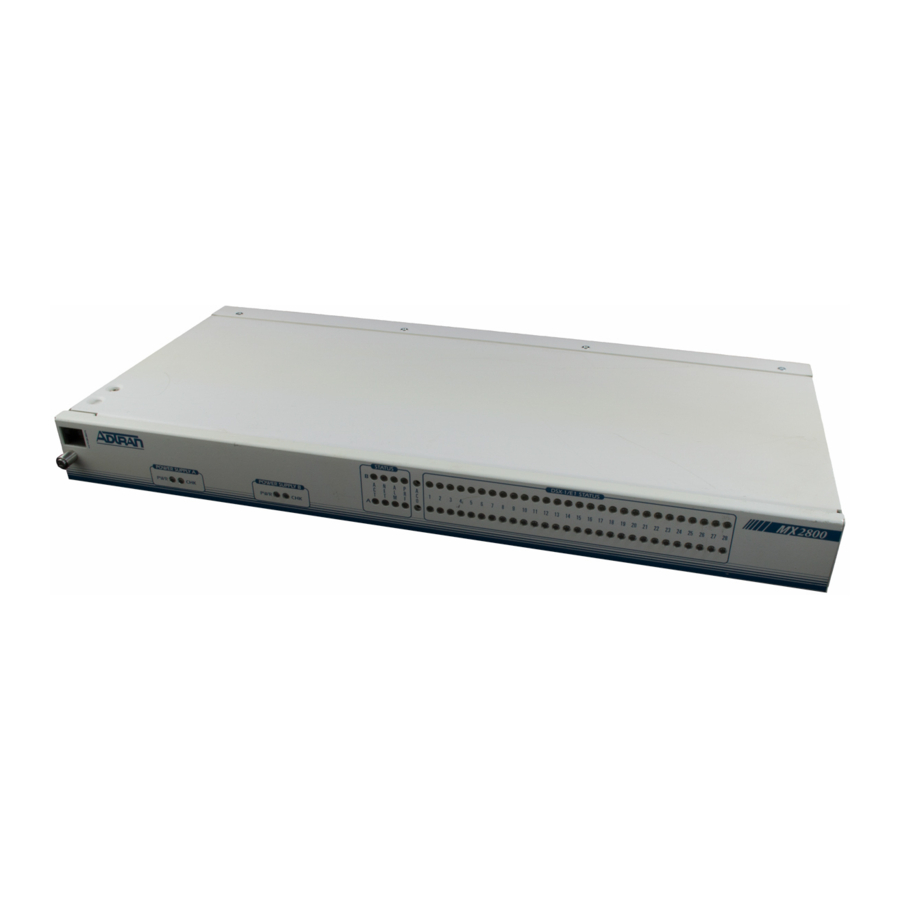
MX2800
M13 Multiplexer
User Manual
4200290L1
AC Non-Redundant Version with Modem
4200290L2
AC Redundant Version with Modem
4200290L3
DC Non-Redundant Version with Modem
4200290L4
DC Redundant Version with Modem
4200290L5
AC Non-Redundant Version
4200290L6
AC Redundant Version
4200290L7
DC Non-Redundant Version
4200290L8
DC Redundant Version
1200291L1
Breakout Panel
4175043L1
Battery Backup
1200657L1
Battery Backup Adapter Cable
1200287L1
Amp to Punch-Down Cable
Advertisement
Table of Contents

Related Manuals for ADTRAN MX2800


Summary of Contents for ADTRAN MX2800
- Page 1 MX2800 M13 Multiplexer User Manual 4200290L1 AC Non-Redundant Version with Modem 4200290L2 AC Redundant Version with Modem 4200290L3 DC Non-Redundant Version with Modem 4200290L4 DC Redundant Version with Modem 4200290L5 AC Non-Redundant Version 4200290L6 AC Redundant Version 4200290L7 DC Non-Redundant Version...
- Page 2 Trademark Information OpenView is a trademark of Hewlett-Packard Company. Spectrum is a registered trademark of Cabletron. 901 Explorer Boulevard P.O. Box 140000 Huntsville, AL 35814-4000 Phone: (256) 963-8000 © 2000 ADTRAN, Inc. All rights reserved. Printed in USA.
- Page 3 Advance notification and the opportunity to maintain uninterrupted service are given. 4. If experiencing difficulty with this equipment, please contact ADTRAN for repair and warranty information. The telephone company may require this equipment to be disconnected from the network until the problem is corrected or it is certain the equipment is not malfunctioning.
- Page 4 “Digital Apparatus,” ICES-003 of the Department of Communications. Cet appareil nuerique respecte les limites de bruits radioelectriques applicables aux appareils numeriques de Class A prescrites dans la norme sur le materiel brouilleur: “Appareils Numeriques,” NMB-003 edictee par le ministre des Communications. MX2800 User Manual 61200290L1-1...
- Page 5 The termination on a loop may consist of any combination of devices subject only to the requirement that the total of the Load Numbers of all devices does not exceed 100. 61200290L1-1 MX2800 User Manual...
-
Page 6: Important Safety Instructions
Warranty and Customer Service ADTRAN will replace or repair this product within ten years from the date of ship- ment if it does not meet its published specifications or fails while in service. For detailed warranty, repair, and return information refer to the ADTRAN Equipment Warranty and Repair and Return Policy Procedure. - Page 7 (including, but not limited to, loss of data or information, loss of profits, or loss of use). ADTRAN is not liable for damages for any cause whatso- ever (whether based in contract, tort, or otherwise) in excess of the amount paid for the item.
- Page 8 MX2800 User Manual 61200290L1-1...
-
Page 9: Table Of Contents
Breakout Panel....................... 1-4 Battery Backup ......................1-4 Chapter 2. Installation and Operation Unpack, Inspect, Power Up ....................2-1 Receiving Inspection..................... 2-1 ADTRAN Shipments Include..................2-1 Power Up........................2-2 Rackmount Installation ...................... 2-4 Connecting the Breakout Panel................... 2-5 Rear Panel ..........................2-6 LAN Port ........................ - Page 10 SNMP Management Options..................3-19 Trap IP Addresses ....................3-19 Trap Generation ....................3-19 Read Community Name ..................3-24 Write Community Name ................... 3-24 Trap Community Name ..................3-24 System Security ......................3-24 Password ......................3-24 Terminal Timeout ....................3-24 MX2800 User Manual 61200290L1-1...
- Page 11 Chapter 5. Statistics Viewing Statistical Information ..................5-1 DS3 Statistics........................5-2 24 Hour Alarm History ..................5-2 Performance Parameters ..................5-4 DS2 Statistics........................5-7 24 Hour Alarm History ..................5-7 Performance Parameters ..................5-8 T1/E1 Statistics......................5-10 61200290L1-1 MX2800 User Manual...
- Page 12 Power Supply Recovery Mode ..................8-3 Power Supply and Source Recovery Mode ..............8-4 Battery Backup Mode ......................8-5 Appendix A. Pinouts......................A-1 Appendix B. Specifications Summary ................. B-1 Appendix C. Acronyms/Abbreviations................ C-1 Appendix D. Glossary ..................... D-1 Index ..........................Index1 MX2800 User Manual 61200290L1-1...
-
Page 13: List Of Figures
List of Figures Figure 2-1. DC Power Connector ..................2-3 Figure 2-2. The Breakout Panel..................2-6 Figure 2-3. MX2800 Rear View ..................2-7 Figure 2-4. MX2800 Front Panel ..................2-9 Figure 2-5. Terminal Main Menu..................2-11 Figure 3-1. Configuration Main Menu ................3-1 Figure 3-2. - Page 14 Figure 7-3. Circuit and Network Failure Recovery Mode ..........7-5 Figure 8-1. Non-Redundant Power Mode............... 8-2 Figure 8-2. Power Supply Failure Recovery Mode ............8-3 Figure 8-3. Power Supply and Source Failure Recovery Mode ........8-4 Figure 8-4. Battery Backup System .................. 8-5 MX2800 User Manual 61200290L1-1...
- Page 15 Table 7-1. Configuration Requirements for Circuit Recovery ........7-4 Table A-1. Craft Port Pin Assignments................A-1 Table A-2. LAN Port Pin Assignments................A-2 Table A-3. Modem Port Pin Assignments..............A-2 Table A-4. Amp Pin Assignments .................. A-3 61200290L1-1 MX2800 User Manual...
- Page 16 List of Tables MX2800 User Manual 61200290L1-1...
-
Page 17: Chapter 1. Introduction
Introduction Chapter 1 PRODUCT OVERVIEW The MX2800 is an M13 multiplexer that consolidates T1 and E1 signals into a T3 circuit. This unit provides a cost-effective, versatile tool for combining independent T1s, E1s, or a combination of the two over the same T3 circuit. -
Page 18: Controller Card 1:1 Redundancy
Chapter 1. Introduction The major features of the MX2800 are as follows: • Built-in 1:1 redundancy • Hot-swappable controller cards • Independent, dual-load sharing, redundant power supplies • Embedded SNMP and Telnet management through 10BaseT ethernet or SLIP/PPP dialup •... -
Page 19: T3 Overview
T3 OVERVIEW A T3 provides the same bandwidth as 28 T1s. Typically, leasing a T3 line costs the same as eight to ten T1s. Using the MX2800, a single T3 can provide internet connectivity and voice (local and long distance) to individual sites across up to 28 individual DSX-1s. T3 is also extremely cost effective for backhauling local and long distance voice. -
Page 20: Telnet
TELNET Telnet provides a password-protected, remote login facility to the MX2800 that allows a remote user to control the MX2800 through the terminal menus. Only one Telnet session may be active at a time. -
Page 21: Chapter 2. Installation And Operation
Chapter 2 UNPACK, INSPECT, POWER UP Receiving Inspection Carefully inspect the MX2800 for any damage that might have occurred in shipment. If damage is suspected, file a claim immediately with the carrier and contact ADTRAN Technical Support (see the end of this manual for phone numbers). Keep the original shipping container to use for future shipment or verification of damage during shipment. -
Page 22: Power Up
120 VAC power receptacle. Power to the AC version of the MX2800 must be provided from a grounded 120 VAC, 60 Hz receptacle. The DC version of the MX2800 is provided with two four-position modular terminal lug connectors. -
Page 23: Figure 2-1. Dc Power Connector
Table 2-1. DC Connector Symbol Definitions Symbol Definition PWR FAIL Battery backup connection. If AC fails, a trap is sent to alert user. Negative side of DC power source (usually -48V) Positive side of DC power source (usually ground) Frame Ground 61200290L1-1 MX2800 User Manual... -
Page 24: Rackmount Installation
Use copper conductors only. RACKMOUNT INSTALLATION The MX2800 can be mounted into a standard 19- or 23-inch equipment rack. (See Establishing Terminal Connection on page 2-10 for information on terminal configuration.) Follow these steps to... -
Page 25: Connecting The Breakout Panel
Chapter 2. Installation and Operation Install the mounting flanges on each side of the MX2800 at one of the three available positions. Be sure to install the flanges with the screws provided. After the flanges have been installed, position the MX2800 at the correct location within the rack and secure the mounting flanges to the mounting rails of the rack. -
Page 26: Rear Panel
REAR PANEL The MX2800 rear panel is equipped with a LAN port, a modem port, two alarm output terminal blocks, an external clock interface, two sets of DS3 in/out jacks, two Amphenol (Amp) connectors, and DC/AC power connections. -
Page 27: Lan Port
Power DC power connection Ground stud 115 VAC 50/60Hz AC power connection Figure 2-3. MX2800 Rear View LAN Port port is an 8-pin modular connector that provides a 10BaseT ethernet LAN interface. This interface is used for SNMP and Telnet control. -
Page 28: Modem Port
MODEM line (POTS) connection for the internal V.34 modem. The MX2800 can be configured as a dial-in host and also as a dial- out-on-Trap device (meaning that the unit dials out to a specified host to report error conditions). Configure the modem parameters... -
Page 29: Dsx-1/E1 Interfaces
The DC and AC power connections are described earlier in this chapter on page 2-2. FRONT PANEL The MX2800 faceplate is shown in Figure 2-4. Descriptions of each part of the front panel follow. Figure 2-4. MX2800 Front Panel 61200290L1-1... -
Page 30: Craft Port
DB-9 female connector and the 8-pin to 8-pin modular cable). Establishing Terminal Connection To connect the MX2800 to a VT 100 terminal, follow this procedure: Configure the VT 100 terminal for 9600, 19200, 38400, or 57600 baud, 8-bit characters, no parity, and one stop bit (xxxx, 8N1). -
Page 31: Navigating Within The Menus
The letter displayed in the upper left-hand corner of the terminal menu indicates which controller card is active (A or B). Navigating Within the Menus Navigate within the MX2800 terminal menus using the following procedures: If you want to... Press... -
Page 32: Aco Buttons
Chapter 2. Installation and Operation The MX2800 M menu consists of the following sections: Status Provides information on the current state of the DS3, power supplies, system, DS2s, and T1/E1 lines. See the chapter Status on page 4-1 for more detailed information. -
Page 33: Led Descriptions
Chapter 2. Installation and Operation LED Descriptions The MX2800 has LED status indicators for the power supplies, the DS3 state, the controller cards, and the individual T1s/E1s. These LEDs are identified as follows: Power Supply A/B The PWR LED is active when the unit is on and receiving full power. - Page 34 Non-Critical Alarm Sup- pressed ( button was pushed) green solid Normal (All OK) red flash (once per event) Single/Burst CV red blinking Continuous Code Violations red solid XCV Threshold Exceeded (see XCV Threshold on page 3-4) 2-14 MX2800 User Manual 61200290L1-1...
-
Page 35: T1/E1 Status Leds
The condition descriptions vary depending on whether the LEDs represent T1s or E1s of the active controller card or the controller card on standby. Table 2-4 provides LED definitions for the active and standby cards. 61200290L1-1 MX2800 User Manual 2-15... -
Page 36: Table 2-4. T1/E1 Led Conditions
3-12) amber solid In Test (Local) amber blinking In Test (Remote) red/amber alternating In Test + Alarm Normal (All OK) or N/A (in the case of E1 Standby configuration) Card red blinking T1/E1 Failure 2-16 MX2800 User Manual 61200290L1-1... -
Page 37: Chapter 3. Configuration
Configuration Chapter 3 To configure the MX2800, use a 10BaseT ethernet connection, a SLIP/PPP modem port, or a VT 100 terminal. Figure 3-1 shows the main configuration terminal menu, and Figure 3-2 shows the menu tree. ONFIGURATION Figure 3-1. Configuration Main Menu... -
Page 38: Figure 3-2. Configuration Menu Tree
Trap Community Name System Security Password Terminal Timeout Date & Time Via XMODEM Utilities From a TFTP Server Miscellaneous Circuit Identification Resetting the System Syslog Setup Save Config Save on Logout Figure 3-2. Configuration Menu Tree MX2800 User Manual 61200290L1-1... -
Page 39: Network Interface
NETWORK INTERFACE Select N to access the network configuration ETWORK NTERFACE parameters (see Figure 3-3). Configure the MX2800 network settings to match the DS3 signal received from the service provider. Figure 3-3. Network Configuration Menu DS3 Configuration Use the DS3 C... - Page 40 EXT CLK Remote Loopbacks Enabling this option allows the MX2800 to respond to remote loopback requests received over the DS3 Far End Alarm and Control (FEAC) channel when operating in C-bit parity mode. When disabled, all loopback requests are ignored.
-
Page 41: Protection Configuration
Chapter 3. Configuration Protection Configuration The MX2800 houses two controller cards for 1:1 protection against hardware failure. The two cards can also provide network protection, supporting two T3 circuits simultaneously. The selections in this menu allow you to customize the unit’s protection... -
Page 42: Miscellaneous
. or 1 DS2 Configuration The MX2800 can individually frame each of the seven DS2 streams in M12 (four T1s) or G.747 (three E1s) format. When set to M12 T1), the four T1s for the selected group are framed per ANSI T1.107. -
Page 43: T1/E1State
Enter A PPLY . You can now either leave the menu or continue to enter SETTINGS new F and L numbers for other lines. Remember to apply IRST the settings when you finish each setting. 61200290L1-1 MX2800 User Manual... -
Page 44: T1/E1 Line Coding
T1s (or E1s) to the same ULTIPLE value at the same time. See Set Multiple on page 3-7 for a description of the S selection, entering the line code for ULTIPLE each line. Figure 3-7. T1/E1 Line Coding Menu MX2800 User Manual 61200290L1-1... -
Page 45: T1/E1 Line Length
T1/E1 Line Length Set the line length for each T1 interface according to the distance from the MX2800 to your DTE device (see Figure 3-8). Set to -7.5 dB if the attached DTE device only supports DS1 levels. The E1 L is not selectable and remains at 0-3000 . -
Page 46: T1/E1 Circuit Protection
T1/E1s to the same ULTIPLE value at the same time. See Set Multiple on page 3-7 for a description of the S selection, entering E ULTIPLE NABLED ISABLED 3-10 MX2800 User Manual 61200290L1-1... -
Page 47: T1/E1 Line Identification
Enter user-configurable text strings to name the individual T1/E1 lines (see Figure 3-11). You can enter up to 18 alpha-numeric characters in this field, including spaces and special characters (such as an underbar). Figure 3-11. Line Identification Menu 61200290L1-1 MX2800 User Manual 3-11... -
Page 48: Xcv Threshold
1,000,000 bits received on a T1/E1 line contains a code violation. SYSTEM MANAGEMENT Configure the MX2800 for management through SNMP, Telnet, or a VT 100 interface (see Figure 3-12). Embedded SNMP and Telnet are available via a SLIP/PPP modem port or 10BaseT ethernet interface. -
Page 49: Management Options
Chapter 3. Configuration Management Options Local IP Address Enter the MX2800 IP address. This IP address applies to the LAN or modem port (when configured for PPP or SLIP). This address is available from the network administrator. Gateway IP Address Enter the gateway IP address of the MX2800. - Page 50 Chapter 3. Configuration Primary and Secondary Phone Numbers When the MX2800 dials out to send a trap, it first dials the P RIMARY . If the call is unsuccessful, it tries the S HONE UMBER ECONDARY . Attempts between the two numbers continue until...
- Page 51 Chapter 3. Configuration Dialout On Trap Enable or disable the MX2800’s ability to dial out to report traps. configured for VT 100 reports error conditions in ODEM plain ASCII with the following information: • The Unit ID value programmed in the C...
-
Page 52: Alarm Relays
1010s are received in the informa- tion bits. This indicates that there is a transmis- sion fault located either at or upstream from the transmitting terminal. LOS* The unit has lost the network Rx signal. 3-16 MX2800 User Manual 61200290L1-1... - Page 53 Note: This is a critical alarm only when Card A is not installed or is not working. Protection All data has been routed from the primary card Switch* to the stand-by card. *Sounds critical alarm. 61200290L1-1 MX2800 User Manual 3-17...
- Page 54 Temperature Power supply card temperature is above nor- High mal. Temperature Power supply card temperature is so high that Critical it will soon shut off completely. 3-18 MX2800 User Manual 61200290L1-1...
-
Page 55: Snmp Management Options
SNMP Management Options Trap IP Addresses Enter up to five IP addresses of SNMP managers to which the MX2800 sends traps. Trap Generation Use this menu (see Figure 3-15) to designate which error conditions will cause the unit to send trap messages. - Page 56 Temperature the power supply card is getting too hot. High Temperature the power supply card temperature is so high Critical that it will soon shut off completely. 3-20 MX2800 User Manual 61200290L1-1...
- Page 57 The controller card is receiving excessive code violations, exceeding the threshold set by the user (see XCV Threshold on page 3-4). In/Out Test the DS3 is going in and out of test (applies to the Active Controller Card only). 61200290L1-1 MX2800 User Manual 3-21...
- Page 58 Comn Eqpt Fail the remote unit’s active controller card is re- ceiving a common equipment failure message from the network. 3-22 MX2800 User Manual 61200290L1-1...
- Page 59 T1/E1. DS1 Eqpt Fail a service-affecting equipment failure is being reported by the far-end. DS1 Eqpt Fail a non-service-affecting equipment failure is be- ing reported by the far-end. 61200290L1-1 MX2800 User Manual 3-23...
-
Page 60: Read Community Name
Read Community Name Enter the authentication strings used for SNMP management. Match the MX2800 to the SNMP manager for read privileges. Write Community Name Enter the authentication strings used for SNMP management. Match the MX2800 to the SNMP manager for write privileges. -
Page 61: Ip Security
(13:15:25). Miscellaneous Equipment Identification These fields allow you to store information that identifies the unit. Information provided for the far-end is read-only. Local informa- tion is read/write from this menu. Figure 3-16. Equipment Identification Menu 61200290L1-1 MX2800 User Manual 3-25... -
Page 62: Syslog Setup
You can enter up to 32 alpha-numeric characters in this field, including spaces and special characters (such as an underbar). This information is locally stored and displayed in the upper right-hand corner of the MX2800 terminal screens (see Figure 3-16). Facility ID/Location ID/Frame ID/Unit and Equipment Codes These fields provide user-configurable text strings to identify the MX2800 over the network. -
Page 63: Save On Logout
UNIX machine or a PC. Options include Local 0 - 7. Save on Logout Enable this function to save the configuration when you log out. Disable if you do not want to save the configuration. 61200290L1-1 MX2800 User Manual 3-27... -
Page 64: Utilities
Chapter 3. Configuration UTILITIES The U menu (see Figure 3-17) allows you to view MX2800 TILITIES system information (including self-test results) for both controller cards, revert to default configuration settings, flash-load a new version of software, and reset the system. Possible results for the self-test are listed in the chart following Figure 3-17. -
Page 65: Updating Software
. Enter the CHEDULE ESET number of hours you want to elapse before the reset takes place. Once a value is entered, the C option ANCEL CHEDULED ESET appears, along with a reset countdown clock. 61200290L1-1 MX2800 User Manual 3-29... -
Page 66: Save Configuration
Chapter 3. Configuration SAVE CONFIGURATION Commits the current configuration changes to nonvolatile memory. If this option is not selected after making changes to the configuration, the unit reverts to its previous configuration when powered down. 3-30 MX2800 User Manual 61200290L1-1... -
Page 67: Chapter 4. Status
Status Chapter 4 View MX2800 status information by selecting 1-S from the TATUS menu (see Figure 4-1). The Information for the DS3, DS2s, T1/ E1 lines, power supplies, and controller cards is provided. Figure 4-1. Status Menu DS3 STATE Displays the current state of the DS3. The following sections describe the DS3 status fields in detail. -
Page 68: State
The unit is currently in test mode. See Diagnos- In Test tics on page 6-1 for information on the test type. Alarm This field displays the current alarm condition of the MX2800. Possible conditions are given in the following chart: Condition Description Normal No alarms are currently being received. -
Page 69: Remote
Idle The unit detects an idle sequence from the net- work. Service is immediately available for use. Remote This field indicates the current state of the remote MX2800. Possible conditions are given in the following table: Condition Description Normal The far-end MX2800 is ready to pass data. -
Page 70: Power Supply State
Temp High The power supply card temperature is abnormal- ly high. Temp Critical The power supply card temperature is so high that it will soon shut off completely. MX2800 User Manual 61200290L1-1... -
Page 71: System State
A power supply card has failed. Card Failure A controller card is not passing data. The M Excessive has been ex- WITCHING HRESHOLD Switches ceeded. See Max. Switch Threshold on page 3-5. Switched A card switch has occurred. 61200290L1-1 MX2800 User Manual... -
Page 72: Card A/Card B
Unit is in Circuit Protection Mode and everything is healthy, unit is in Network Protection Mode and a failure on the network has occurred. None One controller card is installed, the unit is in Circuit Protection Mode and the sec- ondary card has failed. MX2800 User Manual 61200290L1-1... -
Page 73: Card Comm
The X-bits (X1 and X2) are set to zero. The unit is receiving an AIS (blue) alarm condition from the network across the DS2. AIS alarms occur when the unit receives unframed all ones. 61200290L1-1 MX2800 User Manual... -
Page 74: T1/E1 State
(and therefore display nothing). ACKNOWLEDGE ALARMS (ACO) This selection allows you to remotely turn off an active alarm. It is the software equivalent of the button (described in the section ACO Buttons on page 2-12). MX2800 User Manual 61200290L1-1... -
Page 75: Chapter 5. Statistics
(divided into 96 15-minute intervals), and the totals for the previous 24 hours. Also, a cumulative alarm count is given. This count continues indefinitely until reset by the user. Figure 5-1. Main Local Statistics Menu Screen 61200290L1-1 MX2800 User Manual... -
Page 76: Ds3 Statistics
Figure 5-2. DS3 Statistics Menu 24 Hour Alarm History The MX2800 keeps track of alarms for both the near and far ends of the network. View alarm history information in one of the three time period selections, or view a cumulative alarm count. -
Page 77: Figure 5-3. Ds3 Current Alarm Count Screen
Number of times the unit has detected an idle se- quence from the network. The count given reflects the number of times the alarm or state has occurred (rather than the number of seconds the alarm was active). Figure 5-3. DS3 Current Alarm Count Screen 61200290L1-1 MX2800 User Manual... -
Page 78: Performance Parameters
Figure 5-6 on page 5-6). Unavailable Seconds (UAS) Time in seconds that the network port is unavailable for data delivery. This means that the T3 link is down or in test, or that the signaling state is down. MX2800 User Manual 61200290L1-1... -
Page 79: Figure 5-5. Ds3 Performance Parameters (Current 15 Minutes)
Number of seconds with 44 or more PCVs, one or more out-of- frame defects, or a detected incoming AIS. This count is not incre- mented when UASs are counted. P-Bit Coding Violations (PCV) Number of coding violation (CV) error events that have occurred. 61200290L1-1 MX2800 User Manual... -
Page 80: Figure 5-6. Ds3 Performance Parameters (24 Hour History)
Number of times an F-bit framing error has occurred. M-Bit Errors (MBE) Number of times an M-bit framing error has occurred. Far End Block Errors (FEBE) Number of times the far-end unit has received a C-parity or framing error. MX2800 User Manual 61200290L1-1... -
Page 81: Ds2 Statistics
DS2 Statistics 24 Hour Alarm History The MX2800 keeps track of RAI, OOF, and AIS alarms for each of the seven DS2s. View alarm history information in one of the three time period selections, or view a cumulative alarm count. -
Page 82: Performance Parameters
96 15-minute intervals; use the up and down arrow keys to scroll between the PBERR and FBERR menus. See Figure 5-10 on page 5-9 and Figure 5-11 on page 5-9. MX2800 User Manual 61200290L1-1... -
Page 83: Figure 5-10. Ds2 Performance Parameters (Current 15 Minutes)
Chapter 5. Statistics Figure 5-10. DS2 Performance Parameters (Current 15 Minutes) Figure 5-11. DS2 PBERR 24-Hour Alarm History 61200290L1-1 MX2800 User Manual... -
Page 84: T1/E1 Statistics
Chapter 5. Statistics T1/E1 Statistics The MX2800 keeps track of L OSS OF IGNAL LARMS IPOLAR , AIS L , and AIS C IOLATION OUNTS LARMS ARRIER LARMS for each of the T1s and E1s (see Figure 5-12). View this information in one of the three time period selections, or view a cumulative alarm count. -
Page 85: Chapter 6. Diagnostics
Diagnostics Chapter 6 The D menu allows you to initiate loopback tests from IAGNOSTICS the MX2800. Figure 6-1 shows the main D menu. From IAGNOSTICS this menu select T1/E1, DS3, or DS2 L . Once this OOPBACKS selection is made, a second menu appears displaying the types of tests available. -
Page 86: T1/E1 Loopbacks
DSX-1/E1 transmitters, but all data received by the DSX-1/E1 loop side is ignored and substituted with the network data. See Figure 6-3 on page 6-3 for an illustration of this test. MX2800 User Manual 61200290L1-1... -
Page 87: Analog Network
LIU while the T1/E1 loop side loopback occurs deep into the LIU through the receiver, receive equalizer, transmit jitter attenuator, and finally, through the T1/E1 transmit drivers. See Figure 6-5 on page 6-4 for an illustration of this test. 61200290L1-1 MX2800 User Manual... -
Page 88: Codec Line/Net
(28 of 28) Figure 6-6. Codec Loopback Remote Loopback performs a loopback of the selected T1/E1 on EMOTE OOPBACK the far-end M13 multiplexer. If an MX2800 is located at the far end, an A is executed when a R NALOG ETWORK OOPBACK EMOTE is engaged. -
Page 89: Csu Loopback
CSU loop-up pattern and begin sending an unframed 511 pattern towards the CSU. If the CSU device responded to the CSU loop-up pattern, the MX2800 will check the incoming pattern for errors. Additional menu items will appear to show the state of pattern synchronization, error count, and a clear error count option (see Figure 6-7). -
Page 90: Line Bert
Figure 6-7. Diagnostics Menu with BERT Selected Line BERT A Line B enables the MX2800 to perform a “head-to-head” test towards the CSU. Selecting Line B will replace all incoming network traffic for the selected T1 with an unframed 511 pattern towards the CSU. -
Page 91: Ds3 Loopbacks
DS3 will be inserted back into the network without modification. See Figure 6-9 on page 6-8 for an illustration of this test. If a L loopback is active when the MX2800 is operating in the L OCAL timing mode, the timing source for the DS3 is effectively removed from the circuit. -
Page 92: Digital Diagnostics
DS3, and passed through both directions of the DS3 LIU. During this test, the incoming DS3 is disconnected from the DS3 receiver and the outgoing DS3 signal is substituted in its place. See Figure 6-11 on page 6-9 for an illustration of this test. MX2800 User Manual 61200290L1-1... -
Page 93: Remote Loopback
Figure 6-11. Metallic Diagnostics Loopback Test Remote Loopback performs a loopback on the far-end M13 EMOTE OOPBACK multiplexer. If an MX2800 is located at the far end, a L is executed when a R is engaged. This OOPBACK EMOTE OOPBACK... -
Page 94: Ds2 Network
MUX/DMUX (1 of 7) (1 of 7) DSX-3 DSX-3 MUX/DMUX MUX/DMUX CODEC CODEC T1/E1 LIU T1/E1 LIU (28 of 28) (28 of 28) (28 of 28) (28 of 28) Figure 6-13. DS2 Network Loopback Test 6-10 MX2800 User Manual 61200290L1-1... -
Page 95: Chapter 7. Circuit And Network Redundancy
Circuit and Network Redundancy Chapter 7 The MX2800 provides backup measures of protection for both circuit and network failure. The following sections describe the three possible modes of operation: • Non-Redundant Mode, which offers no backup protection, is described on page 7-2. -
Page 96: Non-Redundant Mode
Chapter 7. Circuit and Network Redundancy NON-REDUNDANT MODE In Non-Redundant Mode, the MX2800 houses only one controller card and only one network connection is available. There is no failure protection. In the event of a failure, an alarm is initiated and the front panel LEDs reflect the condition. -
Page 97: Circuit Failure Recovery Mode
In Circuit Failure Recovery Mode, two controller cards are installed and a single DS3 line is coming in (see Figure 7-2). In this mode, the MX2800 can continue operating in the event of a controller card failure. When both cards are healthy, the primary card actively processes data while the secondary card stands by ready to take over if the first fails. -
Page 98: Table 7-1. Configuration Requirements For Circuit Recovery
E1s that redundant switching should occur on. Config > T1/E1 Interface > XCV Threshold 1E-3 (see the following note) The XCV Threshold settings are based on the error rates considered ac- ceptable on the DS3 or DS1 before switching. MX2800 User Manual 61200290L1-1... -
Page 99: Circuit And Network Failure Recovery Mode
For example if Card A fails, then control switches to Card B and DS3 B. An important feature of the MX2800 is its ability to internally re- route the network connection if a controller card and the opposite network connection fail. - Page 100 Chapter 7. Circuit and Network Redundancy MX2800 User Manual 61200290L1-1...
- Page 101 Power Loss Recovery Chapter 8 The MX2800 provides backup measures of protection for both power supply and power source failure. The following sections describe the possible modes of operation: • Non-Redundant Power Mode, which offers no backup protection, is described on page 8-2.
-
Page 102: Chapter 8. Power Loss Recovery
Chapter 8. Power Loss Recovery NON-REDUNDANT POWER MODE In Non-Redundant Power Mode, the MX2800 houses only one power supply card and only one power source is available. There is no power failure protection. If a power supply card fails, then the unit is down until the card is repaired or replaced. -
Page 103: Power Supply Recovery Mode
In Power Supply Recovery Mode, two power supply cards are installed and connected to a single power source (see Figure 8-2). In this mode, the MX2800 can continue operation in the event of a power supply failure, without interrupting service. The power supplies are load sharing, so either power supply can provide power for the entire unit. -
Page 104: Power Supply And Source Recovery Mode
MX2800 handles any combination of power source or power supply failure. Much like the backup design for the controller cards, the MX2800 is able to internally re-route the power source if a power supply card and the opposite power source fail. For example, in the illustration... -
Page 105: Battery Backup Mode
This PS/BC (part number 4175043L1) provides -48 VDC to the MX2800. It receives 115 VAC through a standard plug and wall socket. The PS/BC maintains the battery at peak charge (-48 V) at all times. - Page 106 Chapter 8. Power Loss Recovery MX2800 User Manual 61200290L1-1...
-
Page 107: Appendix A. Pinouts
Pinouts Appendix A The following tables give the pin assignments for the connectors located on the MX2800. For more information on these connectors, see the chapter Installation and Operation on page 2-1. Table A-1. Craft Port Pin Assignments RJ Pin#... -
Page 108: Table A-2. Lan Port Pin Assignments
Table A-3. Modem Port Pin Assignments Description 1, 2, 3 not used Ring 6, 7, 8 not used The modem port pin assignments apply to units equipped with an inter- nal modem (4200290L1, L2, L3, and L4). MX2800 User Manual 61200290L1-1... -
Page 109: Table A-4. Amp Pin Assignments
TIP 23 RING 23 TIP 24 RING 24 TIP 25 RING 25 TIP 26 RING 26 TIP 27 RING 27 TIP 28 RING 28 FGND FGND Table A-4 applies to both the Amp connectors. Out DSX1/E1 61200290L1-1 MX2800 User Manual... - Page 110 Appendix A. Pinouts MX2800 User Manual 61200290L1-1...
-
Page 111: Appendix B. Specifications Summary
Specifications Summary Appendix B SPECIFICATIONS AND FEATURES This section describes the standard specifications and features incorporated in the MX2800. DSX-3 Network Interface Channelized DS3 Line length: short (less than 50 feet) and long (greater than 50 feet) Framing format: M13 and C-bit parity Line rate: 44.736 Mbps... - Page 112 Dial out “cry for help” SNMP/Telnet Integrated 10BaseT ethernet MIB II (RFC 1213), RFC 1215 and RFC 1407 compliant. ADTRAN Enterprise MIB for extended monitoring and control/ configuration. Alarms External alarm contacts for critical and noncritical alarms Normally open and normally closed pinout...
- Page 113 Appendix B. Specifications Summary Power AC version: 120 VAC, 30 W DC version: 48 VDC, 30W Physical Dimensions: 7.86“D x 17.0“W x 1.7“H Weight: 5.5 lbs. (redundant); 4.5 lbs. (non-redundant) 61200290L1-1 MX2800 User Manual...
- Page 114 Appendix B. Specifications Summary MX2800 User Manual 61200290L1-1...
-
Page 115: Appendix C. Acronyms/Abbreviations
Consultive Committee for International Telephony and Telegraphy CCV....C-bit coding violation CD ..... carrier detect CES....C-bit errored seconds CO ..... central office CPE....customer premise equipment CRC ....cyclic redundancy check CS ...... clear to send 61200290L1-1 MX2800 User Manual... - Page 116 FBE..... F-bit errors FCC ....Federal Communications Commission FDL ....facility datalink FEAC ....far-end alarm and control FEBE ....far end block error HSSI ....high-speed serial interface IP ......internet protocol KA...... keep alive MX2800 User Manual 61200290L1-1...
- Page 117 P-bit coding violation PCV ....P-bit errored seconds PES ....POP ....point of presence PPP ....point-to-point protocol PRF ....performance PSES ....P-bit severely errored seconds public switched telephone network PSTN....61200290L1-1 MX2800 User Manual...
- Page 118 TA....... terminal equipment available TD ...... transmit data TDM....time division multiplexing TM ..... test mode TR ...... data terminal ready Tx ....... transmit UAS ....unavailable seconds WAN....wide area network XCV ....excessive coding violations MX2800 User Manual 61200290L1-1...
-
Page 119: Appendix D. Glossary
Does not necessarily equal the bit rate. BERT bit error rate test. A test that uses any of a number of stress patterns to test T3, T1, FT1, and DDS circuits. 61200290L1-1 MX2800 User Manual... - Page 120 The provider of the telecommunication services to the customer site. Carriers can be local telephone companies, regional telephone companies, or any inter- exchange carrier such as AT&T, Sprint, or MCI. MX2800 User Manual 61200290L1-1...
- Page 121 (2) to provide a time base. customer premises equipment. All telecommunications terminal equipment located on the customer premises, including telephone sets, private branch exchanges (PBXs), data terminals, and customer-owned, coin-operated tele- phones. 61200290L1-1 MX2800 User Manual...
- Page 122 Appendix D. Glossary craft port The electrical interface between the MX2800 and the control terminal. The con- trol terminal is used to communicate commands to the unit. channel service unit. A device used to connect a digital phone line coming in from the phone company to either a multiplexer, channel bank, or directly to another device producing a digital signal;...
- Page 123 The ultimate source or destination of data flowing through a network (some- times referred to as DTE). end user Subscriber who uses (rather than provides) telecommunications services. errored seconds. A second with one or more coding violations (CVs). 61200290L1-1 MX2800 User Manual...
- Page 124 In a T3 circuit, an idle code consists of a sequence of 1100 over the entire payload bandwidth. in-band Signaling (dialing, diagnostics, management, configuration, etc.) over the same channel used for data. internet protocol. A protocol which provides for transmitting blocks of data between hosts identified by fixed-length addresses. MX2800 User Manual 61200290L1-1...
- Page 125 Acronym for modulator/demodulator. Equipment that converts digital signals to and from analog signals. Used to send digital signals over analog phone lines. monitor To watch or listen to a signal non-intrusively. multi-point circuit A single communications circuit that has more than two terminations. 61200290L1-1 MX2800 User Manual...
- Page 126 A set of rules controlling the orderly exchange of information between stations in data communications networks or systems. PSTN public switched telephone network. Usually refers to the world wide voice tele- phone network available for public use. MX2800 User Manual 61200290L1-1...
- Page 127 LOS or OOF not caused by an alarm indication signal (AIS) that persists for more than two seconds. remote configuration A feature designed into ADTRAN products that allows remote units to be con- figured from a local unit or a VT 100 compatible terminal. router A device that supports communications between networks.
- Page 128 A standard for trunk interface between a network access device and a packet network that defines signaling for data rates greater than 19.2 kbps. VT 100 A non-intelligent terminal or terminal emulation mode used for asynchronous communications. Used to configure the MX2800. D-10 MX2800 User Manual 61200290L1-1...
- Page 129 A T3 yellow alarm is an indication sent back toward the source of a failed trans- mit circuit in a DS3 two-way transmission path. The X-bits (X1 and X2) are set to zero. 61200290L1-1 MX2800 User Manual D-11...
- Page 130 Appendix D. Glossary D-12 MX2800 User Manual 61200290L1-1...
-
Page 131: Index
8-3 AIS Carrier Alarms 5-10 backup T3, routing information to 3-5 AIS Loop Alarms 5-10 BAD BOOT SECTOR 3-28 alarm connectors, MX2800 2-8 BAD CODE CHECKSUM 3-28 Alarm menu BAD RAM ADDRESS 3-28 DS3 State 4-2... - Page 132 System Management 3-12 T1/E1 Alarm Traps 3-23 T1/E1 Interface 3-6 T1/E1 alarms 3-18 Utilities 3-28 T1/E1 State 4-8 configuring the MX2800 3-1 Cancel Scheduled Reset 3-29 configuring the network interface 3-3 Card A/Card B connecting the breakout panel 2-5 Active state 4-6...
- Page 133 DS3 Eqpt Fail SA 3-22 Idle 3-22 LOS 3-22 Facility ID menu 3-26 OOF 3-22 Failure, Card A/Card B 4-6 RAI 3-22 Far End Block Errors (FEBE) 5-6 FBERR 5-8 F-Bit Errors (FBE) 5-6 FEAC 6-4 FEAC channel 3-4 61200290L1-1 MX2800 User Manual Index-3...
- Page 134 Local IP Address menu 3-13 T1/E1 Alarm Traps 3-23 Location ID menu 3-26 Initializing String menu 3-14 installing the MX2800 2-1 24 Hour Alarm History (DS3 statistics) 5-3 Interface menu, T1/E1 3-6 DS2 3-17 Interval starting at:, Performance Parameters (DS3)
- Page 135 Cold Start 3-24 by Cards 3-21 Link Down 3-24 Remote status 4-3 Link Up 3-24 operating the MX2800, overview of 2-1 MIB, SNMP 1-4 options for the MX2800 1-4 Min. Switching Period menu 3-5 Miscellaneous menu 3-25 Miscellaneous menus, network configuration 3-6...
- Page 136 Power Supply Alarm 3-18 Protection Threshold 3-10 Power Supply Alarm Traps 3-20 PWR FAIL, DC connector symbol 2-3 Power Supply State 4-4 PWR LED 2-13 power supplies, hot-swappable 8-2 power supply A/B 2-13 rackmount installation 2-4 Index-6 MX2800 User Manual 61200290L1-1...
- Page 137 7-3 SNMP Management Options 3-19 non-redundant mode 7-2 SNMP, overview 1-3 Refresh All Remote Statistics 5-7 specifications, MX2800 B-1 refreshing remote statistics 5-7 Stand By, Card A/Card B 4-6 Remote all T1/E1 6-9 State menu (DS3 State) 4-2...
- Page 138 LAIS 4-8 LOS 4-8 viewing system information 3-28 OK 4-8 TST 4-8 XCV 4-8 T1/E1 State menu 4-8 Write Community Name 3-24 T1/E1 Statistics menu 5-10 T1/E1 Status LEDs 2-15 Index-8 MX2800 User Manual 61200290L1-1...
- Page 139 XCV Threshold menus DS3 Configuration 3-4 T1/E1 Line Identification 3-12 DS3 3-17 XMODEM updates 3-29 DS3 Alarm Traps Near-end Active and Stand- by Cards 3-21 T1/E1 Alarm Traps 3-23 T1/E1 Alarms 3-18 T1/E1 State 4-8 61200290L1-1 MX2800 User Manual Index-9...
- Page 140 Index Index-10 MX2800 User Manual 61200290L1-1...
- Page 141 (800) 615-1176 Sales (800) 827-0807 Post-Sale Support Please contact your local distributor first. If your local distributor cannot help, please contact ADTRAN Technical Support and have the unit serial number available. Technical Support (888) 4ADTRAN Repair and Return If ADTRAN Technical Support determines that a repair is needed, Technical Support will coordinate with the Customer and Product Service (CAPS) de- partment to issue a Return Material Authorization (RMA) number.
Need help?
Do you have a question about the MX2800 and is the answer not in the manual?
Questions and answers