Invacare meteor User Manual
3-wheeler version/4-wheeler version
Hide thumbs
Also See for meteor:
- User manual (60 pages) ,
- User manual (57 pages) ,
- Service manual (52 pages)
Table of Contents
Advertisement
Advertisement
Table of Contents

Related Manuals for Invacare meteor


Summary of Contents for Invacare meteor
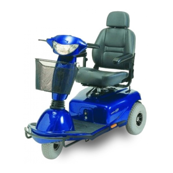
- Page 1 Yes, You Can.® Invacare® Meteor Scooter User Manual...
- Page 2 How can you get in touch with Invacare®? If you have any questions or need support, please contact your authorised Invacare® Dealer, who has the necessary know-how and equipment plus the special knowledge concerning your Invacare® product, and can offer you all-round satisfactory service. Should you wish to contact Invacare® directly, you can reach us in Europe at the following addresses and phone numbers.
- Page 3 +44 (0)1656 776 220 Pencoed uk@invacare.com Bridgend CF35 5HZ eire@invacare.com United Kingdom WWW: www.invacare.co.uk Invacare Mecc San s.r.l. +39 0445 38 00 59 Via Dei Pini, 62 Fax: +39 0445 38 00 34 I - 36016 Thiene (VI) italia@invacare.com ITALIA WWW: www.invacare.it...
- Page 4 Invacare Portugal, Lda +351 225 1059 46 Rua Estrada Velha, 949 : +351 225 1059 47 P-4465-784 Leça do Balio Fax: +351 225 1057 39 Portugal portugal@invacare.com WWW: www.invacare.pt Återförsäljare: (Kundtjänst): +46 (0)8 761 70 90 Invacare® AB Fax (Kundtjänst):...
-
Page 5: Table Of Contents
Table of Contents Chapter Page Introduction Important symbols in this manual ..................10 Important symbols found on the vehicle ................11 Type classification and permissible use................12 Guarantee ..........................12 Indications..........................13 Life expectancy........................13 Safety Notes General Safety Notes ......................14 Safety information with regard to care and maintenance ...........17 Safety Information on Electromagnetic Interference............18 Safety Information on Driving and Freewheel Mode............19 Key features... - Page 6 The Control Panel Control Panel Layout ......................27 6.1.1 Seat Lifter Button ......................28 6.1.2 Status Display.......................28 6.1.3 Battery Charge Display....................29 Driving the Scooter .........................30 Diagnostics and Troubleshooting ..................31 6.3.1 Diagnosing Faults ......................32 Error Codes and Diagnostic Codes..................33 Adjustment features Adjusting the backrest angle ....................36 Moving the seat position forwards or backwards..............37 Disengaging the seat to rotate it or remove it ..............38 Adjusting the armrest width ....................39...
- Page 7 10 Repair Instructions 10.1 Repairing a flat tyre .........................54 10.1.1 Repairing punctures (pneumatic tyres of type 4.00 - 5) ..........55 10.1.1.1 Removal/refitting of rear wheel................55 10.1.1.2 Removal/refitting of front wheel (4-wheel version) ..........57 10.1.1.3 Removal/refitting of front wheel (3-wheel version) ..........59 10.1.1.4 Repairing punctured tyres ..................60 11 Disposal...
-
Page 8: Introduction
The decision whether the model is suitable for the user may only be taken by medical specialists with appropriate aptitude. Invacare® or their statutory representatives can accept no liability in cases in which the mobility product has not been adapted to suit the user's handicaps. - Page 9 This manual contains copyrighted information. It may not be reproduced or copied in whole or in part without the prior written consent of Invacare® or its authorised representative. It may also contain information that pertains to models sold only in certain countries. In this case the information will be clearly marked as pertaining to a particular country-specific version.
-
Page 10: Important Symbols In This Manual
Important symbols in this manual WARNING! This symbol warns you of danger! • Always follow these instructions to avoid injury to the user or damage to the product! EXPLOSION HAZARD! This symbol warns you of an explosion hazard, which, for example, can be caused by excessive tyre pressure in a pneumatic tyre! •... -
Page 11: Important Symbols Found On The Vehicle
Important symbols found on the vehicle This product has been supplied from an environmentally aware manufacturer that complies with the Waste Electrical and Electronic Equipment (WEEE) Directive 2002/96/CE. This product may contain substances that could be harmful to the environment if disposed of in places (landfills) that are not appropriate according to legislation. -
Page 12: Type Classification And Permissible Use
Type classification and permissible use This vehicle was designed for persons whose ability to walk is impaired, but who are still physically and mentally able to operate an electric vehicle. It has been classified according to EN 12184 as a Class C mobility product (for outdoor use). -
Page 13: Indications
Indications The use of this mobility product is recommended for the following indications: The inability or a greatly restricted ability to walk within the scope of the basic requirement to be able to move within one’s own four walls. The need to leave the dwelling place in order to get some fresh air during a short walk or to reach those places generally to be found at close distance to the dwelling and where everyday business is carried out. -
Page 14: Safety Notes
Safety Notes READ WELL BEFORE OPERATION! General Safety Notes Danger of injury if this scooter is used in any other way than the purpose described in this manual! • Adhere strictly to the instructions in this user manual! Danger of injury if the scooter is driven when your ability to drive is impaired by medication or alcohol! •... - Page 15 Danger of injury if the On/Off Button is pressed while the vehicle is in motion, due to it coming to an abrupt, sharp stop! • If you have to brake in an emergency, simply pull the handbrake until the scooter comes to a halt! Only switch the vehicle off while in motion as a last resort! Danger of injury if the scooter is transported in another vehicle with the occupant seated in it!
- Page 16 Invacare® for this purpose! Have all electrical installations done by your authorised Invacare® Dealer! Danger of technical failure and injury if unauthorised spare parts and components are used! • Only use original Invacare® spare parts, which have been approved for use with this vehicle!
-
Page 17: Safety Information With Regard To Care And Maintenance
Safety information with regard to care and maintenance Danger of accident and loss of guarantee if maintenance is insufficient! • For reasons of safety and in order to avoid accidents which result from unnoticed wear, it is important that this electric mobility product undergoes an inspection once every year under normal operating conditions (see inspection plan contained in service instructions). -
Page 18: Safety Information On Electromagnetic Interference
Safety Information on Electromagnetic Interference This electric vehicle was successfully tested in accordance with International standards as to its compliance with Electromagnetic Interference (EMI) Regulations. However, electromagnetic fields, such as those generated by radio and television transmitters, and cellular phones, can influence the functions of electric vehicles. -
Page 19: Safety Information On Driving And Freewheel Mode
Safety Information on Driving and Freewheel Mode Danger of injury if the vehicle tips over! • Only ever negotiate gradients up to the maximum tilt-resistant gradient and only with the backrest in an upright position, and the seat lifter in the lowest position (if installed)! •... - Page 20 Danger of injury if the vehicle tips over! (Continued) • Never use the vehicle to transport more than one person! • Do not exceed the maximum permissible load! • When loading the vehicle, always distribute the weight evenly! Always try to keep the centre of gravity of the vehicle in the middle, and as close to the ground as possible! •...
-
Page 21: Key Features
Key features 1) Driving lever 2) Lever for adjusting steering column inclination 3) Control panel 4) Handbrake / wheel lock 5) Keyswitch (ON/OFF) 6) Release lever for sliding seat rails (front right below seat) 7) Release lever for swivelling and removing seat (right below seat) 8) Disengaging lever... -
Page 22: Driving
Driving Before driving for the first time... Before you take your first trip, you should familiarise yourself well with the operation of the vehicle and with all operating elements. Take your time to test all functions and driving modes. NOTE: If installed, make sure to properly adjust and use the posture belt each time you use the wheelchair. -
Page 23: Taking Obstacles
Taking Obstacles Your Invacare® Meteor can climb obstacles and kerbstones up to 11 cm in height. CAUTION: Danger of Tipping Over! • Never approach obstacles at an angle but at 90 degrees as shown below. • Put your backrest into an upright position before climbing an obstacle. -
Page 24: Driving Up And Down Gradients
Driving up and down gradients The maximum safe slope for the Invacare® Meteor depends on the version and the load capacity: 10 km/h versions: • 3-wheeler (up to 175 kg load): 15° (26%) • 4-wheeler (up to 200 kg load): 15°... -
Page 25: Parking And Stationary
Parking and stationary When parking your vehicle or if your vehicle is stationary for a prolonged period: • Switch the vehicle's power system off (key switch). • Activate the parking brake (if available). 4.4.1 Using the handbrake as a parking brake (option) Activating the brake •... -
Page 26: Pushing The Scooter By Hand
Pushing the scooter by hand The motors of the scooter are equipped with automatic brakes, preventing the scooter from rolling away out of control when the power supply is switched off. When pushing the scooter, the magnetic brakes must be disengaged. Disengaging Motors Danger of the vehicle running away! •... -
Page 27: The Control Panel
The Control Panel Control Panel Layout Seat Lifter button (if installed) Battery charge indicator Hazard flashers Horn Right turn signal Driving speed adjustment Throttle lever Plug for external charger Reduced Speed Mode 10) Left turn signal 11) Lights... -
Page 28: Seat Lifter Button
6.1.1 Seat Lifter Button • Press the button to activate the Seat Lifter (if installed). The LED above the button lights up. • Raise or lower the seat using the throttle lever. • Press the button once again to de-activate the Seat Lifter. The throttle lever reverts back to driving mode. -
Page 29: Battery Charge Display
6.1.3 Battery Charge Display • All diodes lit: full driving range • Only red and yellow diodes lit: decreased drive range. Charge batteries at end of journey. • Only red diodes lit / flashing: battery reserve = very low drive range! Charge batteries immediately! NOTE Total discharge protection: After a certain drive time on reserve battery power the electronics... -
Page 30: Driving The Scooter
Gently pull the right driving lever towards you to drive forwards. • Gently pull the left driving lever towards you to drive backwards. NOTE The controller is programmed with standard values ex-works. Your Invacare® Dealer can program it to fit your requirements. NOTE: •... -
Page 31: Diagnostics And Troubleshooting
Diagnostics and Troubleshooting The electronics system provides diagnostics information to assist technicians to diagnose and correct faults within the scooter system. The existence of a fault will cause the status light to flash in bursts, separated by a pause. The nature of the fault is indicated by the number of flashes in each burst, also referred to as the Flash Code. -
Page 32: Diagnosing Faults
Check that all cables are connected correctly. If only the leftmost diode of the battery charge display is PERMANENTLY ON Contact your authorised Invacare® Dealer If the leftmost diode of the battery charge display is FLASHING Count the number of flashes and refer to the next section. -
Page 33: Error Codes And Diagnostic Codes
Error Codes and Diagnostic Codes Blink Fault Consequence Comments code for the Scooter Battery must be Continues to • The batteries are discharged. Charge the charged drive battery as soon as possible. Battery voltage too Stops driving • The batteries are depleted. Charge batteries. - Page 34 • There is a defect in the braking coil or in the cabling. Check the magnetic brake and cabling for open or short-circuited circuitry. Contact your Invacare® dealer. No neutral position Stops driving • Drive lever is not in neutral when the when switching keyswitch was turned.
- Page 35 • The motor or its cabling is defective Check the cabling for open or short- circuited circuitry. Miscellaneous Stops driving • Contact your Invacare® dealer. internal fault Push/freewheel Stops driving • The Scooter has exceeded the mode error permissible maximum speed during pushing or freewheeling.
-
Page 36: Adjustment Features
Adjustment features Adjusting the backrest angle The backrest is held firm by a metal plate on both sides. Both plates have four holes which allow the backrest to be adjusted for various angles. You can do this by selecting various combinations for the holes. -
Page 37: Moving The Seat Position Forwards Or Backwards
Moving the seat position forwards or backwards The disengaging lever for adjusting the seat is located front right below the seat • Pull the lever (1) to disengage the seat. • Slide the seat forwards or backwards into the required position. •... -
Page 38: Disengaging The Seat To Rotate It Or Remove It
Disengaging the seat to rotate it or remove it The seat can be turned to one side to make getting in and out of the scooter easier. The seat is also easier to remove from this position. The lever for disengaging the seat is located under the seat (1) on the right. -
Page 39: Adjusting The Armrest Width
Adjusting the armrest width The hand wheels for adjusting the armrests are located under the seat (1). • Turn the hand wheels to loosen the fixing for the armrest. • Adjust the armrests to the required width. • Retighten the handwheels... -
Page 40: Adjusting The Armrest Height
Adjusting the armrest height The hand wheels for adjusting the armrest height are located on the armrests (1). • Turn the hand wheels to loosen the fixing for the armrest (1). • Adjust the armrests to the required height. • Retighten the handwheels... -
Page 41: Adjusting The Seat Height
Adjusting the seat height The seat height can be adjusted to the following heights (measured from chassis / floor): • 46 / 64 cm • 48 / 66 cm • 49 / 68 cm • 51 / 71 cm WARNING! Danger of disengaging the drive unintentionally! •... -
Page 42: Adjusting The Suspension
• Adjust the seat height. • Reinsert the bolt and tighten. Adjusting the suspension The Meteor suspension can be individually adjusted. These adjustments should only be carried out by trained specialists. Please contact your authorised Invacare specialist dealer. -
Page 43: Electrical System
Electrical System Electronics Protection System The vehicle's electronics are equipped with an overload-protection system. If the motors are put under considerable strain for a longer period of time (for example, when driving up a steep hill) and especially when the ambient temperature is high, then the electronic system could overheat. -
Page 44: The Main Fuse
NOTE A defective main fuse may be replaced only after checking the entire electric system. An Invacare® specialised dealer must perform the replacement. You can find information on the fuse type in chapter "Technical specifications" starting on page 63. Batteries 8.2.1... - Page 45 The batteries cannot be overcharged with the specified charger. Please use only charging devices in Class 2. This class of chargers may be left unattended during charging. All charging devices which are supplied by Invacare® comply with these requirements.
-
Page 46: Charging The Batteries
• Only ever use the battery charger supplied with your vehicle, or a charger that has been approved by Invacare®. Danger of electric shock and damage to the battery charger if it is allowed to get wet! • Protect the battery charger from water. - Page 47 The Meteor has two sockets for charging the batteries. One is located on the rear edge of the operating console (1) (maximum charge current 8A). The other is located on the front side of the battery and motor compartment (2) (maximum charge current 15A).
-
Page 48: Removing And Fitting Batteries
8.2.3 Removing and fitting batteries WARNING: Danger of injury if the batteries are not handled correctly during assembly and maintenance work! • New batteries should be installed by authorised technicians! • Observe the warnings on the batteries! • Take into account the heavy weight of the batteries! •... -
Page 49: Removing The Batteries
8.2.3.1 Removing the batteries Requirements: • 2x open-ended spanners 11 mm • Remove seat (see chapter "Releasing seat for turning or removal" on page "38") • Remove the battery and motor compartment covers by pulling on the rear edge. • Disconnect the two battery cable plug connections (1). - Page 50 • Release the battery holder strap. • Removing the batteries. • Loosen the black cable battery clamp on the negative battery terminal with the open-ended spanner, and remove the cable. • Loosen the red cable battery clamp on the positive battery terminal with the open-ended spanner, and remove the cable.
-
Page 51: How To Handle Damaged Batteries Correctly
Only ever transport damaged batteries in an appropriate acid-resistant receptacle. • Wash all objects that have come into contact with acid with lots of water. Disposing of dead or damaged batteries correctly Dead or damaged batteries can be given back to your dealer or directly to Invacare®. -
Page 52: Care And Maintenance
Care and maintenance NOTE: Have your vehicle checked once a year by an authorised Invacare® dealer in order to maintain it's driving safety and roadworthiness. Cleaning the vehicle When cleaning the vehicle, pay attention to the following points: • Only use a damp cloth and gentle detergent. - Page 53 • Clean all parts carefully. Once a year you should have your vehicle inspected and serviced by your authorised dealer. A complete checklist of necessary maintenance work can be found in the Service Manual, which can be obtained from Invacare®.
-
Page 54: Repair Instructions
"Technical specifications" on page 63, or consult the Service Manual, available from Invacare® (in this connection please see the addresses and phone numbers in section "How can you get in touch with Invacare®?" on page 2). In case you require assistance, please contact your Invacare® Dealer. -
Page 55: Removal/Refitting Of Rear Wheel
10.1.1 Repairing punctures (pneumatic tyres of type 4.00 - 5) 10.1.1.1 Removal/refitting of rear wheel CAUTION: It is possible to damage the scooter if the wheels are re-fixed without using copper paste after repairing a flat tyre! • When refitting the wheel, copper paste must be applied to the drive shaft or axle! This ensures that the wheel rim does not solidly jam onto the axle over time so that it cannot be removed! Requirements:... - Page 56 Problems when removing wheel? It may be necessary to use a special tool Please ask your Invacare® dealer to help you. Reassembly Reassembly takes place in reverse order. Make sure that you refit the wheel on the same side and for the same direction of travel as...
-
Page 57: Removal/Refitting Of Front Wheel (4-Wheel Version)
10.1.1.2 Removal/refitting of front wheel (4-wheel version) CAUTION: It is possible to damage the scooter if the wheels are re-fixed without using copper paste after repairing a flat tyre! • When refitting the wheel, copper paste must be applied to the drive shaft or axle! This ensures that the wheel rim does not solidly jam onto the axle over time so that it cannot be removed! Requirements:... - Page 58 Reassembly Reassembly takes place in reverse order. Make sure that you refit the wheel on the same side and for the same direction of travel as previously.
-
Page 59: Removal/Refitting Of Front Wheel (3-Wheel Version)
10.1.1.3 Removal/refitting of front wheel (3-wheel version) Requirements: • 2x open-ended spanners 17 mm • Carefully tip the scooter onto one side. • Remove the wheel locknuts (1) using both open-ended spanners, then remove the wheel from the fork. Reassembly Reassembly takes place in reverse order. -
Page 60: Repairing Punctured Tyres
10.1.1.4 Repairing punctured tyres Requirements (general) • inner tube repair set or a new inner tube • talcum powder • open-ended spanner, 13 mm • Remove valve cap. • De-inflate the tyre by pressing in the centre valve pin. • Remove the four nuts (1) on the rear of the wheel using the 13 mm open-ended spanner. - Page 61 Did the old inner tube get wet during the repair? If you repaired the old inner tube and reused it, and it became wet during repair, it is much easier to refit it into the wheel if you lightly powder it with talcum powder. •...
-
Page 62: Disposal
Electric components and printed circuit boards are disposed of as electronic scrap. • Exhausted or damaged batteries can be returned to your medical equipment supplier or Invacare®. • Disposal must be carried out in accordance with the respective national legal provisions. -
Page 63: Technical Specifications
Technical specifications 3-wheeler version 4-wheeler version Electrical system Motor (10 km/h) • 400 W • 400 W Motor (12.8 km/h, 8 • 400 W • 400 W MPH, UK) Motor (15 km/h) • 400 W • 400 W Batteries • 2 x 50 AH •... - Page 64 3-wheeler version 4-wheeler version Dimensions Height • 123 cm* • 123 cm* Width • 65.5 cm* • 65.5 cm* Length (with bumper and • 141 cm* • 146 cm* anti-tip device) Seat height (measured • 46 / 64 cm* • 46 / 64 cm* from chassis / from floor, •...
- Page 65 3-wheeler version 4-wheeler version Travelling performance Speed • 10 km/h • 10 km/h • 12.8 km/h (8 MPH, UK) • 12.8 km/h (8 MPH, UK) • 15 km/h • 15 km/h Max. tilt-resistant climbing ability 10 km/h version • up to 175 kg operating load: •...
-
Page 66: Inspections Performed
It is confirmed by stamp and signature that all jobs listed in the inspection schedule of the Service and Repair Instructions have been properly performed. The list of the inspection jobs to be performed can be found in the Service Manual which is available through Invacare®. Delivery Inspection...
Need help?
Do you have a question about the meteor and is the answer not in the manual?
Questions and answers