Table of Contents
Advertisement
Quick Links
M I C R O P H O N E S A N D E L E C T R O N I C C O M P O N E N T S
The Shure Models M64 and M64-2E Stereo Pre-
amplifiers are designed to furnish the voltage gain
and equalization necessary to operate magnetic
phono cartridges (such as the Shure DYNETIC
Cartridges), and tape playback heads with audio
amplifiers that have no equalization. In addition, the
units may be used without equalization for micro-
phones or as buffer amplifiers.
Typical Applications:
Conversion of stereo record playing systems
l
from ceramic to magnetic cartridges.
Preamplifier for microphones.
l
Low gain buffer amplifier where long cable
l
lengths are extended to a preamplifier input.
Advantages include complete freedom from micro-
phonics, extremely low noise, the ability to use
15m (50 ft) or more of output cable, and years of
maintenance-free performance. The operating tem-
perature range is from 7°C (20°F) to 57°C (135°F).
The Model M64 operates on 108-132 volts, 50/60
Hz power line, or from an auxiliary 24 to 36 volt dc
supply such as the Shure Model A67B Battery Power
Supply. The M64-2E is identical to the M64 except
that it operates on a line voltage of 216-264 volts,
50/60 Hz.
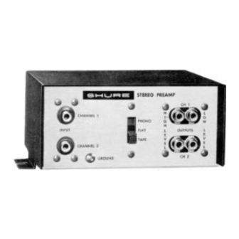
The Model M64 and M64-2E feature a single 3-
position slide switch for selecting equalization for
Phono, Tape, or Flat. The Phono position provides
the Standard RIAA Equalization for phono records.
The Tape position provides the Standard 7½ IPS
NAB Equalization for tape, and the Flat position
provides a flat amplifier for microphones or as a
buffer amplifier for magnetic phono cartridges when
long lines or switching systems are necessary
between the turntable and main equalized pre-
amplifier. (NOTE: When used as a buffer amplifier,
the Low Level Outputs should be used). The input
and output jacks will accept standard phono plugs.
There are input jacks for Channel 1 and Channel 2;
output jacks for Ch. 1 High Level, Ch. 1 Low Level,
Ch. 2 High Level, and Ch. 2 Low Level.
Copyright 1984, Shure Brothers Inc.
27A2076 (DB)
222 HARTREY AVE., EVANSTON, IL, 60204 U.S.A.
AREA CODE 312/866-2200 • CABLE: SHUREMlCRO
TWX: 910-231-0048
TELEX: 72-4349
GENERAL
SPECIFICATIONS
Gain
Gain measured at 1 kHz with input through 680
ohms and output terminated in 47 kilohms.
®
Equalization
Switch Position
Flat
Phono
Tape
Frequency Response
Flat:
± 2 dB from 20 Hz to 20 kHz
Phono:
± 2 dB of the Standard RIAA curve from
40 Hz to 15 kHz
Tape:
± 2 dB of the 7½ IPS NAB curve from
50 Hz to 15 kHz
TYPICAL FREQUENCY RESPONSE
Distortion
Under 1% total harmonic distortion for an output
of 2 volts at 1 kHz in Phono, Tape or Flat positions.
In the Phono position the total harmonic distortion
is less than 1% at 30 Hz with 2 volts output.
Clipping Level
The minimum input clipping levels at 1 kHz are:
Flat: 250 mV
Phono: 100 mV
Tape: 80 mV
Channel Separation
50 dB or better at 1 kHz
Channel Balance
Channels matched within 2 dB at 1 kHz
DATA SHEET
MODELS M64 AND M64-2E
STEREO PREAMPLIFIERS
Low
High Level
Level
output
output
+27.5 dB
+ 4.0 dB
+34.5 dB
+11.0 dB
+37.0 dB
+13.5 dB
FIGURE 1
Printed in U.S.A.
Advertisement
Table of Contents

Related Manuals for Shure M64


Summary of Contents for Shure M64
- Page 1 Hz power line, or from an auxiliary 24 to 36 volt dc supply such as the Shure Model A67B Battery Power Supply. The M64-2E is identical to the M64 except that it operates on a line voltage of 216-264 volts, TYPICAL FREQUENCY RESPONSE 50/60 Hz.
- Page 2 A suitable power line isola- tion transformer should be used with such Battery Operation equipment. The M64 and M64-2E may be powered by three Eveready 216 Batteries in series or equivalent power source connected to 30 V.D.C. jacks. Battery OPERATION Connections: life is over 100 hours.
- Page 3 R13 and R14 (330 ohm resistor across the 1000 d. If ac power operated, insert the M64 or M64-2E ohm resistor). The extra lead length of R13 power line cord into a proper power outlet,...
- Page 4 MODEL M64 CIRCUIT NOTES: 1. A L L C A P A C I T O R S I N M F D A N D 1 0 0 V O L T S O R M O R E U N L E S S OTHERWISE SHOWN.
Need help?
Do you have a question about the M64 and is the answer not in the manual?
Questions and answers