
Related Manuals for ASROCK Rack C2750D4I


Summary of Contents for ASROCK Rack C2750D4I
-
Page 1: User Manual
C2750D4I C2550D4I User Manual Version 1.1 Published December 2013 Copyright©2013 ASRock Rack INC. All rights reserved. -
Page 2: Copyright Notice
ASRock Rack has been advised of the possibility of such damages arising from any defect or error in the manual or product. -
Page 3: Table Of Contents
Contents 1 Introduction ............5 1.1 Package Contents ..........5 1.2 Specifications ............6 1.3 Unique Features ..........12 1.4 Motherboard Layout ..........13 1.5 I/O Panel ............. 17 1.6 Block Diagram ............. 18 2 Installation ............19 2.1 Pre-installation Precautions ........ 19 2.2 Screw Holes ............ - Page 4 3.6 Server Management ..........51 3.7 Event Logs ............52 3.8 Security Screen ........... 53 3.9 Boot Screen ............54 3.10 Exit Screen ............55 4 Software Support ..........56 4.1 Install Operating System ........56 4.2 Support CD Information ........56 4.2.1 Running Support CD ........
-
Page 5: Introduction
Chapter 1: Introduction Thank you for purchasing ASRock Rack C2750D4I / C2550D4I mother- board, a reliable motherboard produced under ASRock Rack’s consistently stringent quality control. It delivers excellent performance with robust de- sign conforming to ASRock Rack’s commitment to quality and endurance. -
Page 6: Specifications
1.2 Specifications C2750D4I Form Factor Mini-ITX Physical Status Dimension 6.7'' x 6.7'' (17.0 cm x 17.0 cm) ® Intel Octa Core Avoton C2750 Processor Processor System Socket FCBGA1283 SOC Max. 64GB DDR3 ECC UDIMM Capacity - 4 x 240-pin DDR3 DIMM slots Socket - Support up to 64GB DDR3 ECC and UDIMM... - Page 7 SEL2 jumper) Front Panel BIOS Type 64Mb AMI UEFI Legal BIOS - Plug and Play (PnP) - ACPI 1.1 Compliance Wake Up Events System BIOS BIOS - SMBIOS 2.3.1 Support Features - DRAM Voltage Multi-adjustment - ASRock Rack Instant Flash...
- Page 8 Operation temperature: 10°C ~ 35°C Environment Temperature / Non operation temperature: -40°C ~ 70°C * For detailed product information, please visit our website: http://www.asrock.com ® Since Intel Edisonville platform does not support RSTe feature, it is decided by OS inbox driver behavior.
- Page 9 C2550D4I Form Factor Mini-ITX Physical Status Dimension 6.7'' x 6.7'' (17.0 cm x 17.0 cm) ® Intel Quad-Core Avoton C2550 Processor Processor System Socket FCBGA1283 SOC Max. 64GB DDR3 ECC UDIMM Capacity - 4 x 240-pin DDR3 DIMM slots Socket - Support up to 64GB DDR3 ECC and UDIMM System...
- Page 10 SEL2 jumper) Front Panel BIOS Type 64Mb AMI UEFI Legal BIOS - Plug and Play (PnP) - ACPI 1.1 Compliance Wake Up Events System BIOS BIOS - SMBIOS 2.3.1 Support Features - DRAM Voltage Multi-adjustment - ASRock Rack Instant Flash...
- Page 11 Operation temperature: 10°C ~ 35°C Environment Temperature / Non operation temperature: -40°C ~ 70°C * For detailed product information, please visit our website: http://www.asrock.com ® Since Intel Edisonville platform does not support RSTe feature, it is decided by OS inbox driver behavior.
-
Page 12: Unique Features
1.3 Unique Features Instant Flash Instant Flash is a BIOS flash utility embedded in Flash ROM. This convenient BIOS update tool allows you to update your BIOS without entering operating systems ® first like MS-DOS or Windows . With this utility, you can press the <F6>... -
Page 13: Motherboard Layout
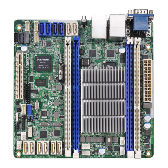
1.4 Motherboard Layout C2750D4I 17.0cm (6.7 in) ATXPWR1 DDR3_A2 (64 bit, 240-pin module) DDR3_A1 (64 bit, 240-pin module) USB 2.0 Top: REAR_FAN2 REAR_FAN1 T: USB_0 IPMI B: USB_1 LAN2 LAN1 CPU_FAN2 CPU_FAN1 64Mb BIOS UID_SW_LED1 SATA_0 DDR3_B1 (64 bit, 240-pin module) DDR3_B2 (64 bit, 240-pin module) SATA_1 SATA_2... - Page 14 ATX Power Connector (ATXPWR1) 2 x 240-pin DDR3 DIMM Slots (DDR3_A1, DDR3_A2) Rear Fan Connector (REAR_FAN1) Rear Fan Connector (REAR_FAN2) CPU Fan Connector (CPU_FAN1) CPU Fan Connector (CPU_FAN2) 2 x 240-pin DDR3 DIMM Slots (DDR3_B1, DDR3_B2) SATA3 Connector (SATA3_M0, White) SATA3 Connector (SATA3_M1, White) USB Selection Jumper (USB_SEL1) SATA3 Connector (SATAIII_M0, White)
- Page 15 C2550D4I 17.0cm (6.7 in) ATXPWR1 DDR3_A2 (64 bit, 240-pin module) DDR3_A1 (64 bit, 240-pin module) USB 2.0 Top: REAR_FAN2 REAR_FAN1 T: USB_0 IPMI B: USB_1 LAN2 LAN1 CPU_FAN2 CPU_FAN1 64Mb BIOS UID_SW_LED1 SATA_0 DDR3_B1 (64 bit, 240-pin module) DDR3_B2 (64 bit, 240-pin module) SATA_1 SATA_2 SATA3_M0...
- Page 16 ATX Power Connector (ATXPWR1) 2 x 240-pin DDR3 DIMM Slots (DDR3_A1, DDR3_A2) Rear Fan Connector (REAR_FAN1) Rear Fan Connector (REAR_FAN2) CPU Fan Connector (CPU_FAN1) CPU Fan Connector (CPU_FAN2) 2 x 240-pin DDR3 DIMM Slots (DDR3_B1, DDR3_B2) SATA3 Connector (SATA3_M0, White) SATA3 Connector (SATA3_M1, White) USB Selection Jumper (USB_SEL1) SATA3 Connector (SATAIII_M0, White)
-
Page 17: I/O Panel
1.5 I/O Panel 1 Serial Port (COM1) 5 LAN RJ-45 Port (LAN2)** 2 Dedicated IPMI LAN Port* 6 USB 2.0 Ports (USB_0-1) 3 LAN RJ-45 Port (LAN1)** 7 D-Sub Port (VGA1) 4 UID Switch/LED (UID_SW_LED1) * There are two LEDs on each LAN port. Please refer to the table below for the LAN port LED indications. -
Page 18: Block Diagram
1.6 Block Diagram 33MHz LPC BUS... -
Page 19: Installation
Chapter 2: Installation Before you install the motherboard, study the configuration of your chassis to ensure that the motherboard fits into it. 2.1 Pre-installation Precautions Take note of the following precautions before you install motherboard com- ponents or change any motherboard settings. Make sure to unplug the power cord before installing or removing the motherboard. -
Page 20: Installation Of Memory Modules (Dimm)
2.3 Installation of Memory Modules (DIMM) This motherboard provides four 240-pin DDR3 (Double Data Rate 3) DIMM slots, and supports Dual Channel Memory Technology. 1. For dual channel configuration, you always need to install identical (the same brand, speed, size and chip-type) DDR3 DIMM pairs. -
Page 22: Expansion Slots
2.4 Expansion Slot (PCI Express Slot) There is 1 PCI Express slot on the motherboard. PCIE slot: PCIE1 (PCIE 2.0 x8 slot) is used for PCI Express x8 lane width graphics cards. Installing an expansion card Step 1. Before installing an expansion card, please make sure that the power supply is switched off or the power cord is unplugged. -
Page 23: Jumpers Setup
2.5 Jumpers Setup The illustration shows how jumpers are setup. When the jumper cap is placed on pins, the jumper is “Short”. If no jumper cap is placed on pins, the jumper is “Open”. The illustration shows a 3-pin jumper whose pin1 and pin2 are “Short”... -
Page 24: Onboard Headers And Connectors
2.6 Onboard Headers and Connectors Onboard headers and connectors are NOT jumpers. Do NOT place jumper caps over these headers and connectors. Plac- ing jumper caps over the headers and connectors will cause permanent damage to the motherboard! Serial ATA3 Connectors These eight Serial ATA3 (SATA3) connectors sup- (SATA_0:... - Page 25 USB 2.0 Header Besides two default USB 2.0 USB_PWR (9-pin USB_2-3) ports on the I/O panel, there (see p.13 or 15, No. 22) is one USB 2.0 header on DUMMY this motherboard. Each USB 2.0 header can support two USB 2.0 ports. USB_PWR TPM Header This connector supports...
- Page 26 PLED (System Power LED): Connect to the power status indicator on the chassis front panel. The LED is on when the system is operating. The LED keeps blinking when the sys-tem is in S3 sleep state. The LED is off when the system is in powered off (S5).
-
Page 27: Fan Connectors
Front and Rear Please connect the fan Fan Connectors cables to the fan connectors (4-pin FRNT_FAN1) +12V and match the black wire to FAN_SPEED (see p.13 or 15, No. 17) FAN_SPEED_CONTROL the ground pin. All fans sup- ports Fan Control. (4-pin FRNT_FAN2) (see p.13 or 15, No. - Page 28 Though this motherboard provides a 4-Pin CPU fan (Quiet Fan) connector, 3-Pin CPU fans can still work successfully even with- out the fan speed control function. If you plan to connect a 3-Pin CPU fan to the CPU fan connector on this motherboard, please connect it to Pin 1-3.
- Page 29 BMC SMB Headers This header is used for the (5-pin BMC_SMB_1) SM BUS devices. (see p.13 or 15, No. 26) (5-pin BMC_SMB_2) (see p.13 or 15, No. 25) (5-pin BMC_SMB_3) (see p.13 or 15, No. 20)
-
Page 30: Driver Installation Guide
2.7 Driver Installation Guide To install the drivers to your system, please insert the support CD to your optical drive first. Then, the drivers compatible to your system can be auto- detected and listed on the support CD driver page. Please follow the order from top to bottom to install those required drivers. -
Page 31: Uefi Setup Utility
Chapter 3: UEFI SETUP UTILITY 3.1 Introduction This section explains how to use the UEFI SETUP UTILITY to configure your system. The UEFI chip on the motherboard stores the UEFI SETUP UTILITY. You may run the UEFI SETUP UTILITY when you start up the computer. -
Page 32: Navigation Keys
3.1.2 Navigation Keys Use < > key or < > key to choose among the selections on the menu bar, and use < > key or < > key to move the cursor up or down to select items, then press <Enter> to get into the sub screen. -
Page 33: Main Screen
3.2 Main Screen When you enter the UEFI SETUP UTILITY, the Main screen will appear and display the system overview. -
Page 34: Advanced Screen
3.3 Advanced Screen In this section, you may set the configurations for the following items: Stor- age Configuration, ACPI Configuration, Super IO Configuration, Serial Port Console Redirection, PCI Subsystem Settings, PLX 8608 Configuration and Voltage. Setting wrong values in this section may cause the system to malfunction. -
Page 35: Storage Configuration
3.3.1 Storage Configuration Hard Disk S.M.A.R.T. Use this to enable or disable S.M.A.R.T. (Self-Monitoring, Analy- sis, and Reporting Technology). Marvell 9230 SATA3_M0~M3 Operation This item is for Marvell 9230 SATA3_M0~M3 ports. Use this to select Marvell SATA3 mode. Configuration options: [Enabled] and [Disabled]. -
Page 36: Acpi Configuration
3.3.2 ACPI Configuration ACPI HPET Table Enable the High Precision Event Timer for better performance. PCIE Devices Power On Use this item to enable or disable PCIE devices to turn on the sys- tem from the power-soft-off mode. RTC Alarm Power On Use this item to enable or disable RTC (Real Time Clock) to pow- er on the system. -
Page 37: Super Io Configuration
3.3.3 Super IO Configuration Deep Sleep Use this to configure Deep Sleep. The default value is [Disabled]. Serial Port 1 Configuration Use this item to configure the onboard serial port 1. SOL Configuration Use this item to configure the onboard serial port 2. -
Page 38: Serial Port Console Redirection
3.3.4 Serial Port Console Redirection Console Redirection Use this option to enable or disable Console Redirection. Console Redirection Settings Use this option to configure Console Redirection Settings. -
Page 39: Pci Subsystem Settings
3.3.5 PCI Subsystem Settings Above 4G Decoding Use this option to enable or disable 64bit capable devices to be decoded in above 4G address space (only if system supports 64bit PCI decoding). -
Page 40: Plx 8608 Configuration
3.3.6 PLX 8608 Configuration Primary Graphics Adapter This allows you to select [Onboard] or [PCI Express] as the boot graphic adapter priority. The default value is [PCI Express]. Onboard VGA This allows you to enable or disable the Onboard VGA feature. Onboard LAN1 This allows you to enable or disable the Onboard LAN1 feature. -
Page 41: Voltage
3.3.7 Voltage DRAM Voltage Use this to select DRAM Voltage. The default value is [Auto]. -
Page 42: Hardware Health Event Monitoring Screen
3.4 Hardware Health Event Monitoring Screen In this section, it allows you to monitor the status of the hardware on your system, including the parameters of the CPU temperature, motherboard temperature and the critical voltage. CPU_FAN1 Setting This allows you to set the speed of CPU fan 1. The default value is [Smart Fan]. -
Page 43: Intelrcsetup
3.5 IntelRCSetup In this section, you may set the configurations for the following items: Pro- cessor Configuration, Clock Generation Configuration, North Bridge Chip- set Configuration, South Bridge Chipset Configuration and System Event Log. Setting wrong values in this section may cause the system to malfunction. -
Page 44: Processor Configuration
3.5.1 Processor Configuration Intel SpeedStep Technology Intel SpeedStep technology is Intel’s new power saving technol- ogy. Processors can switch between multiple frequencies and volt- age points to enable power saving. The default value is [Enabled]. Configuration options: [Enabled] and [Disabled]. This item will be hidden if the current CPU does not support Intel SpeedStep tech- nology. - Page 45 Intel Turbo Boost Technology Use this item to enable or disable Intel Turbo Boost Mode Tech- nology.Turbo Boost Mode allows processor cores to run faster than marked frequency in specific conditions. The default value is [Enabled]. Active Processor Cores Use this item to select the number of cores to enable in each pro- cessor package.
-
Page 46: Clock Generation Configuration
3.5.2 Clock Generation Configuration Spread Spectrum Enable Spread Spectrum to reduce electromagnetic interference for passing EMI tests. Disable to achieve higher clock speeds when overclocking. -
Page 47: North Bridge Chipset Configuration
3.5.3 North Bridge Chipset Configuration DRAM Frequency If [Auto] is selected, the motherboard will detect the memory module(s) inserted and assign the appropriate frequency auto- matically. -
Page 48: South Bridge Chipset Configuration
3.5.4 South Bridge Chipset Configuration Restore on AC/Power Loss Select the power state after a power failure. If [Power Off] is se- lected, the power will remain off when the power recovers. If [Power On] is selected, the system will start to boot up when the power recovers. - Page 49 SATA Aggressive Link Power Management Use this item to configure Aggressive Link Power Management.
-
Page 50: System Event Log
3.5.5 System Event Log Whea Settings Use this option to configure Windows Hardware Error Architecture. -
Page 51: Server Management
3.6 Server Management System Event Log Enter to configure System Event Logging features during boot. BMC Network Configuration Enter to configure BMC Network parameters. -
Page 52: Event Logs
3.7 Event Logs Change Smbios Event Log Settings This allows you to configure the Smbios Event Log Settings. View Smbois Event Log This allows you to view the Smbios Event Log. -
Page 53: Security Screen
3.8 Security Screen In this section, you may set or change the supervisor/user password for the system. For the user password, you may also clear it. -
Page 54: Boot Screen
3.9 Boot Screen In this section, it will display the available devices on your system for you to configure the boot settings and the boot priority. Setup Prompt Timeout This shows the number of seconds to wait for setup activation key. -
Page 55: Exit Screen
3.10 Exit Screen Save Changes and Exit When you select this option, the following message “Save con- figuration changes and exit setup?” will pop-out. Select [Yes] to save the changes and exit the UEFI SETUP UTILITY. Discard Changes and Exit When you select this option, the following message “Discard changes and exit setup?”... -
Page 56: Software Support
4.2.4 Contact Information If you need to contact ASRock Rack or want to know more about AS- Rock Rack, you’re welcome to visit ASRock Rack’s website at http:// www.asrock.com; or you may contact your dealer for further informa-... -
Page 57: Troubleshooting
Chapter 5: Troubleshooting 5.1 Troubleshooting Procedures Follow the procedures below to troubleshoot your system. Always unplug the power cord before adding, removing or changing any hardware components. Failure to do so may cause physical injuries to you and damages to motherboard components. 1. - Page 58 2. Confirm whether your power supply provides adaquate and stable power. Other problems... 1. Try searching keywords related to your problem on ASRock Rack’s FAQ page: http://www.asrock.com/support/faq.asp 2. Try downloading and updating the latest UEFI on ASRock Rack’s website: http://www.asrock.com/support/download.asp...
-
Page 59: Technical Support Procedures
5.2 Technical Support Procedures If you have tried the troubleshooting procedures mentioned above and the problems are still unsolved, please contact ASRock Rack’s technical support with the following information: 1. Your contact information 2. Model name, BIOS version and problem type. -
Page 60: Net Framework Installation Guide
Chapter 6: Net Framework Installation Guide ® To let Intel RSTe works properly, it is required to install Net Framework. Please follow the steps below to enable “.Net Framework” feature on ® ® Microsoft Windows Server 2008 R2. Installing .Net Framework 3.5.1 (For Server 2008 R2) 1. - Page 61 3. Check the box next to .Net Framework 3.5.1 and then click Next. Click Next to continue.
- Page 62 4. Click Install to start installing .Net Framework 3.5.1. 5. After the installation completes, click Close.
Need help?
Do you have a question about the Rack C2750D4I and is the answer not in the manual?
Questions and answers