Table of Contents
Advertisement
Advertisement
Table of Contents
Troubleshooting

Related Manuals for Yamaha YZF-R1 2000


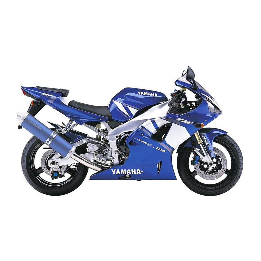
Summary of Contents for Yamaha YZF-R1 2000
- Page 3 FOREWORD This Supplementary Service Manual has been prepared to introduce new service and data for the YZF-R1 2000. For complete service information procedures it is necessary to use this Supplementary Service Manual together with the following manual. YZF-R1 SERVICE MANUAL: 4XV1-AE1...
-
Page 4: Important Manual Information
EB001000 NOTICE This manual was produced by the Yamaha Motor Company, Ltd. primarily for use by Yamaha dealers and their qualified mechanics. it is not possible to include all the knowledge of a mechanic in one manu- al. Therefore, anyone who uses this book to perform maintenance and repairs on Yamaha vehicles should have a basic understanding of mechanics and the techniques to repair these types of vehicles. -
Page 5: How To Use This Manual
EB003000 HOW TO USE THIS MANUAL This manual is intended as a handy, easy-to-read reference book for the mechanic. Comprehensive explanations of all installation, removal, disassembly, assembly, repair and check procedures are laid out with the individual steps in sequential order. 1 The manual is divided into chapters. - Page 6 EB004000 SYMBOLS The following symbols are not relevant to every SPEC vehicle. INFO Symbols 1 to 9 indicate the subject of each chapter. 1 General information 2 Specifications 3 Periodic checks and adjustments 4 Engine 5 Cooling system 6 Carburetor(-s) COOL CARB 7 Chassis...
-
Page 7: Table Of Contents
CONTENTS SPECIFICATIONS GENERAL SPECIFICATIONS ....... . ENGINE SPECIFICATIONS ........CHASSIS SPECIFICATIONS . - Page 8 ELECTRICAL INSTRUMENT FUNCTIONS ....... . . INDICATOR LIGHTS ........COOLANT TEMPERATURE WARNING LIGHT .
-
Page 9: Specifications
SPEC GENERAL SPECIFICATIONS SPECIFICATIONS GENERAL SPECIFICATIONS Item Standard Limit Dimensions Overall length 2,035 mm 2,095 mm (for AUS) Overall width 695 mm Overall height 1,105 mm Seat height 815 mm Wheelbase 1,395 mm Minimum ground clearance 140 mm Minimum turning radius 3,400 mm Weight Wet (with oil and a full fuel tank) -
Page 10: Engine Specifications
SPEC ENGINE SPECIFICATIONS ENGINE SPECIFICATIONS Item Standard Limit Engine Engine type Liquid-cooled, 4-stroke, DOHC Displacement 998 cm Cylinder arrangement Forward-inclined parallel 4-cylinder Bore stroke 58 mm Compression ratio 11.8 : 1 1,000 X 1,100 r/min Engine idling speed Vacuum pressure at engine idling 29.3 kPa (220 mm Hg) speed Standard compression pressure... - Page 11 SPEC ENGINE SPECIFICATIONS Item Standard Limit Camshafts Drive system Chain drive (right) 24.500 X 24.521 mm Camshaft cap inside diameter 24.459 X 24.472 mm Camshaft journal diameter 0.028 X 0.062 mm Camshaft-journal-to-camshaft- cap clearance Intake camshaft lobe dimensions 32.5 X 32.6 mm Measurement A 32.4 mm 24.95 X 25.05 mm...
- Page 12 SPEC ENGINE SPECIFICATIONS Item Standard Limit Valves, valve seats, valve guides Valve clearance (cold) 0.11 X 0.20 mm Intake 0.21 X 0.25 mm Exhaust Valve dimensions Head Diameter Face Width Seat Width Margin Thickness Valve head diameter A 22.9 X 23.1 mm Intake 24.4 X 24.6 mm Exhaust...
- Page 13 SPEC ENGINE SPECIFICATIONS Item Standard Limit Transmission Transmission type Constant mesh, 6-speed Primary reduction system Spur gear Primary reduction ratio 68/43 (1.581) Secondary reduction system Chain drive Secondary reduction ratio 43/16 (2.688) Operation Left-foot operation Gear ratios 1st gear 35/14 (2.500) 2nd gear 35/19 (1.842) 3rd gear...
-
Page 14: Chassis Specifications
SPEC CHASSIS SPECIFICATIONS CHASSIS SPECIFICATIONS Item Standard Limit Front tire Tire type Tubeless Size 120/70 ZR17 (58W) Model (manufacturer) MEZ3Y FRONT (METZELER) D207FQ (DUNLOP) Tire pressure (cold) 0 X 90 kg 250 kPa (2.5 kg/cm , 2.5 bar) 90 X 197 kg 250 kPa (2.5 kg/cm , 2.5 bar) High-speed riding... - Page 15 SPEC CHASSIS SPECIFICATIONS Item Standard Limit Front suspension Suspension type Telescopic fork Front fork type Coil spring/oil damper Front fork travel 135 mm Spring Free length 255 mm Spacer length 85 mm Installed length 242.4 mm Spring rate (K1) 7.35 N/mm (0.75 kgf/mm) 0 X 135 mm Spring stroke (K1) Optional spring available...
- Page 16 SPEC CHASSIS SPECIFICATIONS Item Standard Limit Rear suspension Suspension type Swingarm (link suspension) Rear shock absorber assembly Coil spring/gas-oil damper type Rear shock absorber assembly 65 mm travel Spring Free length 176 mm Installed length 162.5 mm Spring rate (K1) 78.4 N/mm (7.84 kgf/mm) 0 X 65 mm Spring stroke (K1)
-
Page 17: Electrical Specifications
Turn signal light 12 V 21 W Meter light Electric starting system System type Constant mesh Starter motor Model (manufacturer) 5JJ (YAMAHA) Power output 0.75 kW Brushes Overall length 9.8 mm 3.65 mm 4.88 X 7.32 N (488 X 732 gf) Spring force 0.009 X 0.011... - Page 18 SPEC ELECTRICAL SPECIFICATIONS Item Standard Limit Thermo unit Model (manufacturer) 5JJ (NIPPON THERMOSTAT) Fuses (amperage quantity) Main fuse 30 A Headlight fuse 20 A Signaling system fuse 20 A Ignition fuse 15 A Radiator fan fuse 10 A Backup fuse (odometer) 10 A Reserve fuse 30 A...
-
Page 19: Tightening Torques
SPEC TIGHTENING TORQUES TIGHTENING TORQUES ENGINE TIGHTENING TORQUES Tightening Thread torque Item Fastener Q’ty Remarks size size Nm mSkgf Cylinder head Cylinder head Cap nut Generator rotor Bolt Oil/water pump assembly driven Bolt sprocket cover Air induction system hose Clamp Crankcase Bolt See NOTE... -
Page 20: Chassis Tightening Torques
SPEC TIGHTENING TORQUES CHASSIS TIGHTENING TORQUES Tightening Item Item Thread size Thread size Remarks Remarks mSkgf Lower ring nut See NOTE. Engine mounting Front mounting bolts Rear upper mounting bolt Rear under mounting bolts Pinch bolts Exhaust pipe bracket Rear master cylinder NOTE: 1. -
Page 21: Lubrication Points And Lubricant Types
SPEC LUBRICATION POINTS AND LUBRICANT TYPES E202000 LUBRICATION POINTS AND LUBRICANT TYPES ENGINE LUBRICATION POINTS AND LUBRICANT TYPES Lubrication point Lubricant Connecting rod bolts and nuts –13–... -
Page 22: Oil Flow Diagrams
SPEC OIL FLOW DIAGRAMS EB203000 OIL FLOW DIAGRAMS Intake camshaft Exhaust camshaft Crankshaft Oil cooler Oil pipe Oil strainer Oil pump –14–... - Page 23 SPEC OIL FLOW DIAGRAMS Exhaust camshaft Intake camshaft Oil filter –15–...
- Page 24 SPEC OIL FLOW DIAGRAMS Cylinder head Crankshaft –16–...
-
Page 25: Coolant Flow Diagrams
SPEC COOLANT FLOW DIAGRAMS EB203000 COOLANT FLOW DIAGRAMS Thermostat Radiator cap Coolant reservoir Radiator Oil cooler Water jacket joint –17–... - Page 26 SPEC COOLANT FLOW DIAGRAMS Thermostat housing Water pump Radiator Radiator fan –18–...
- Page 27 SPEC COOLANT FLOW DIAGRAMS Radiator Thermo unit –19–...
-
Page 28: Cable Routing
SPEC CABLE ROUTING EB206000 CABLE ROUTING Clutch cable A Properly insert the meter assembly coupler and rubber boot into the Left handlebar switch lead meter assembly. Starter cable B Route the meter assembly lead through the left side of the headlight Main switch lead housing. - Page 29 SPEC CABLE ROUTING G Fasten the headlight lead with a plastic clamp at N Route the thermo switch / temperature sender sub- white tape mark. wire harness to the outside of the radiator cap. H Fasten the wire harness to the headlight housing O Route the right handlebar switch lead behind the boss with a plastic locking tie.
- Page 30 SPEC CABLE ROUTING Rollover valve (California only) C Route the rollover-valve-to-fuel-tank hose to the in- Charcoal canister (California only) side of the fuel hose (California only). Rear brake switch lead D Route the coolant reservoir breather hose over the Timing chain tensioner. timing chain tensioner.
- Page 31 SPEC CABLE ROUTING Starter cable Fuel tank overflow hose and fuel tank breather hose Air induction system vacuum Drive chain sprocket cover hose Coolant hose Air induction system hose EXUP servomotor Sidestand switch lead A Route the air filter case breather hose and air induction system hose Oil level switch lead to the inside of the wire harness.
- Page 32 SPEC CABLE ROUTING C To the connector cover. J Route the sidestand switch lead and oil level switch D Route the seat lock cable over the wire harness. lead to the inside of the drive sprocket cover. E Fasten the wire harness with a plastic clamp. K Do not crush the water pump breather hose and F Make sure the rear flasher light lead coupler and plastic clip.
- Page 33 SPEC CABLE ROUTING N Pass the fuel tank breather hose and the air filter Q To the air filter. drain hose through the inside of the coolant hose. R To the fuel tank. No hose must be inserted into the under cowling. S Insert the fuel tank breather hose into a back side O Pass the air filter drain hose and the coolant reser- nipple of fuel tank.
- Page 34 SPEC CABLE ROUTING Speed sensor lead D Route the EXUP cables behind the swing arm head Charcoal canister (California only) pipe. EXUP cables E Fasten the EXUP cables and engine mount with a EXUP plastic locking tie. A Route the EXUP cables behind the cross tube. B Route the neutral switch lead direct to upper right side.
- Page 35 SPEC CABLE ROUTING Headlight sub-wire harness Neutral switch connector Left handlebar switch lead Battery negative lead Main switch lead Rear brake switch coupler Starter cable Speed sensor coupler Right handlebar switch coupler EXUP cable Throttle cables Fuel tank overflow hose Engine air vent hose Fuel tank breather hose (except for California) EXUP servomotor coupler...
- Page 36 SPEC CABLE ROUTING Engine oil level switch lead Air filter case drain hose Air induction system hose Ignition coil Cover Rivet Screw Coupler Main harness Frame Rear fender –28–...
- Page 37 SPEC CABLE ROUTING A Make sure the headlight lead in the rubber cover. G To the carburetor. B Route the horn lead over the horn bracket and H Route the coolant reservoir tank breather hose up- make sure that the lead has no slack. per the air vent surge tank.
- Page 38 SPEC CABLE ROUTING L Fasten the fuel pump lead, speed sensor lead, tank breather hose have each white mark. neutral switch lead, rear brake light lead, fuel send- S 30 mm (1.17 in) er lead, starter motor lead and EXUP cable with a T Fasten the battery positive lead and starter motor plastic clamp.
- Page 39 SPEC CABLE ROUTING X Fasten the main harness with a plastic band on the D’ At the back side of turning point, battery negative rear fender. lead is fixed to wire harness. Y Position the ground coupler over the main harness. E’...
- Page 40 SPEC CABLE ROUTING I’ Fasten the main harness with a plastic clamp. In- should be not exceed just behind 30 mm of all coupler. O’ 0 X 30 mm sert the plastic clamp into the hole on the frame. J’ Route the charcoal canister hose under the engine P’...
-
Page 41: Periodic Checks And Adjustments
PERIODIC MAINTENANCE AND LUBRICATION INTERVALS EB300000 PERIODIC CHECKS AND ADJUSTMENTS INTRODUCTION This chapter includes all information necessary to perform recommended checks and adjustments. If followed, these preventive maintenance procedures will ensure more reliable vehicle operation, a longer service life and reduce the need for costly overhaul work. This information applies to vehicles already in service as well as to new vehicles that are being prepared for sale. - Page 42 S Adjust headlight beam if necessary. * Since these items require special tools, data and technical skills, have a Yamaha dealer perform the service. NOTE: D The annual checks must be performed once a year unless a 10,000 km or 20,000 km maintenance was performed in the same year.
-
Page 43: Cowlings
COWLINGS EB302020 COWLINGS 5 Nm (0.5 mSkg) Order Job/Part Q’ty Remarks Removing the cowlings Remove the parts in the order listed. Rider and passenger seats Refer to “SEATS”. Rear cowling Bottom cowling Front cowling inner panel (left) Front cowling inner panel (right) Left side cowling Right side cowling Windshield... -
Page 44: Air Filter Case And Ignition Coil Plate
AIR FILTER CASE AND IGNITION COIL PLATE EB302040 AIR FILTER CASE AND IGNITION COIL PLATE Order Job/Part Q’ty Remarks Removing the air filter case and Remove the parts in the order listed. ignition coil plate Rider seat and fuel tank Refer to “SEATS”... -
Page 45: Overhauling The Engine
ENGINE OVERHAULING THE ENGINE AIR INDUCTION SYSTEM 4 Nm (0.4 mSkg) Order Job/Part Q’ty Remarks Removing the air induction system Remove the parts in the order listed. Air induction pipe Air cutoff valve Carburetor joint hose Air intake hose For installation, reverse the removal procedure. -
Page 46: Engine
ENGINE ENGINE 24 Nm (2.4 mSkg) 40 Nm (4.4 mSkg) 55 Nm (5.5 mSkg) 40 Nm (4.0 mSkg) 55 Nm (5.5 mSkg) 24 Nm (2.4 mSkg) Order Job/Part Q’ty Remarks Removing the engine Remove the parts in the order listed. NOTE: Place a suitable stand under the frame and engine. -
Page 47: Installing The Engine
ENGINE EB400700 INSTALLING THE ENGINE 1. Install: S engine assembly a. Install the spacer 1 to the frame. b. Temporally tighten the right front mounting bolt 2 , left front mounting bolt 3 , and wash- ers 4 5 . c. -
Page 48: Cylinder Head
CYLINDER HEAD EB402000 CYLINDER HEAD 50 Nm (5.0 mSkg) 65 Nm (6.5 mSkg) 12 Nm (1.2 mSkg) Order Job/Part Q’ty Remarks Removing the cylinder head Remove the parts in the order listed. Engine Refer to “ENGINE”. Intake and exhaust camshafts Refer to “CAMSHAFTS”. -
Page 49: Crankcase
CRANKCASE CRANKCASE 10 Nm (1.0 mSkg) 10 Nm (1.0 mSkg) Order Job/Part Q’ty Remarks Separating the crankcase Remove the parts in the order listed. Engine Refer to “ENGINE”. Cylinder head Refer to “CYLINDER HEAD”. Pickup coil and pickup coil rotor Refer to “PICKUP COIL”. - Page 50 CRANKCASE 10 Nm (1.0 mSkg) 10 Nm (1.0 mSkg) Order Job/Part Q’ty Remarks Oil/water pump assembly drive sprocket Washer Plate Lower crankcase Dowel pin For installation, reverse the removal procedure. –42–...
-
Page 51: Assembling The Crankcase
2. Apply: S sealant (onto the crankcase mating surfaces and the groove a of the oil baffle plate) Yamaha bond No. 1215 90890-85505 NOTE: Do not allow any sealant to come into contact with the oil gallery or crankshaft journal bear- ings. - Page 52 CRANKCASE 6. Install: S lower crankcase 1 (onto the upper crankcase 2 ) CAUTION: Before tightening the crankcase bolts, make sure that the transmission gears shift cor- rectly when the shift drum assembly is turned by hand. 7. Install: S crankcase bolts NOTE: S Lubricate the bolt threads with engine oil.
-
Page 53: Cooling System
COOL RADIATOR EB500000 COOLING SYSTEM RADIATOR 10 Nm (1.0 mSkg) 20 Nm (2.0 mSkg) 9 Nm (0.9 mSkg) 23 Nm (2.3 mSkg) 4.5 Nm (0.45 mSkg) Order Job/Part Q’ty Remarks Removing the radiator Remove the parts in the order listed. Rider seat and fuel tank Refer to “SEATS”... - Page 54 COOL RADIATOR 10 Nm (1.0 mSkg) 20 Nm (2.0 mSkg) 9 Nm (0.9 mSkg) 23 Nm (2.3 mSkg) 4.5 Nm (0.45 mSkg) Order Job/Part Q’ty Remarks Thermo unit Thermostat assembly breather hose Disconnect. Radiator inlet hose Oil cooler outlet hose Disconnect.
-
Page 55: Carburetors
CARB AIR INDUCTION SYSTEM EAS00507 CARBURETORS AIR INDUCTION SYSTEM AIR INJECTION The air induction system burns unburned ex- haust gases by injecting fresh air (secondary air) into the exhaust port, reducing the emission of hydrocarbons. When there is negative pressure at the exhaust port, the reed valve opens, allowing secondary air to flow into the exhaust port. -
Page 56: Air Induction System Diagrams
CARB AIR INDUCTION SYSTEM EAS00509 AIR INDUCTION SYSTEM DIAGRAMS 1 Reed valve A To the air cutoff valve 2 Air cleaner B To cylinder #1 3 Air cutoff valve D To cylinder #2 4 Carburetor joint (cylinder #1) D To cylinder #3 E To cylinder #4 –48–... -
Page 57: Checking The Air Induction System
CARB AIR INDUCTION SYSTEM EAS00510 CHECKING THE AIR INDUCTION SYSTEM 1. Check: S hoses Loose connection ! Connect properly. Cracks/damage ! Replace. S pipes Cracks/damage ! Replace. 2. Check: S fibre reed 1 S fibre reed stopper S reed valve seat S Cracks/damage ! Replace. -
Page 58: Chassis
CHAS FRONT WHEEL AND BRAKE DISCS EB700002 CHASSIS FRONT WHEEL AND BRAKE DISCS 6 Nm (0.6 mSkg) 72 Nm (7.2 mSkg) 40 Nm (4.0 mSkg) 18 Nm (1.8 mSkg) Order Job/Part Q’ty Remarks Removing the front wheel and brake Remove the parts in the order listed. NOTE: discs Place the motorcycle on a suitable stand... -
Page 59: Installing The Front Wheel
CHAS FRONT WHEEL AND BRAKE DISCS EB700725 INSTALLING THE FRONT WHEEL 1. Lubricate: S wheel axle S oil seal lips Recommended lubricant Lithium soap base grease 2. Install: S brake discs 1 18 Nm (1.8 mSkg) NOTE: S Apply LOCTITE 648 to the threads of the brake disc bolts. -
Page 60: Front And Rear Brakes
CHAS FRONT AND REAR BRAKES EB702202 FRONT AND REAR BRAKES REAR BRAKE MASTER CYLINDER AND BRAKE FLUID RESERVOIR 5 Nm (0.5 mSkg) 30 Nm (3.0 mSkg) 23 Nm (2.3 mSkg) Order Job/Part Q’ty Remarks Removing the rear brake master Remove the parts in the order listed. cylinder and brake fluid reservoir Brake fluid Drain. -
Page 61: Electrical Instrument Functions
3. Push the start switch. If the warning light does not come on while pushing the start switch, have a Yamaha dealer check the electrical circuit. NOTE: This model is equipped with a selfdiagnosis de- vice for the fuel level warning light circuit. -
Page 62: Coolant Temperature Warning Light
3. Push the start switch. If the warning light 1 Coolant temperature gauge does not come on while pushing the start 2 Coolant temperature warning light “ ” switch, have a Yamaha dealer check the electrical circuit. CAUTION: Do not operate the engine if it is overheated. Coolant... -
Page 63: Speedometer Unit
ELEC INSTRUMENT FUNCTIONS SPEEDOMETER UNIT The speedometer unit is equipped with the fol- lowing: S a digital speedometer (which shows riding speed) S an odometer (which shows the total distance traveled) S two tripmeters (which show the distance traveled since they were last set to zero) S a fuel reserve tripmeter (which shows the di- stance traveled on the fuel reserve) S a clock... - Page 64 ELEC INSTRUMENT FUNCTIONS Clock mode To change the display to the clock mode, push the “SELECT” button for at least one second. To change the display back to the odometer modes, push the “SELECT” button. To set the clock: 1. Push the “SELECT” button and “RESET” button together for at least two seconds.
-
Page 65: Electric Starting System
ELEC ELECTRIC STARTING SYSTEM ELECTRIC STARTING SYSTEM STARTER MOTOR 5 Nm (0.5 mSkg) 7 Nm (0.7 mSkg) Order Job/Part Q’ty Remarks Removing the starter motor Remove the parts in the order listed. Rider seat Refer to “SEATS” in chapter 3. Fuel tank Refer to “FUEL TANK”... - Page 66 ELEC ELECTRIC STARTING SYSTEM EB803501 5 Nm (0.5 mSkg) Order Job/Part Q’ty Remarks Disassembling the starter motor Disassembly the parts in the order listed. Starter motor rear cover Bearing Starter motor yoke O-ring Armature assembly Brush Brush holder Starter motor front cover Bearing For assembly, reverse the disassembly procedure...
- Page 67 ELEC ELECTRIC STARTING SYSTEM EB803511 Checking The Starter Motor 1. Check: S commutator Dirt ! Clean with 600 grit sandpaper. 2. Measure: S commutator diameter a Out of specification ! Replace the starter motor. Min. commutator diameter 23.5 mm 3. Measure: S mica undercut a Out of specification ! Scrape the mica to the proper measurement with a hacksaw blade...
- Page 68 ELEC ELECTRIC STARTING SYSTEM 5. Measure: S brush length a Out of specification ! Replace the brushes as a set. Min. brush length 3.65 mm 6. Measure: S brush spring force Out of specification ! Replace the brush springs as a set. Brush spring force 5.28 X 7.92 N 7.
- Page 69 ELEC ELECTRIC STARTING SYSTEM 3. Install: S starter motor yoke 2 S O-rings 1 S starter motor rear cover 3 S bolts 5 Nm (0.5 mSkg) NOTE: Align the match marks a on the starter motor yoke with the match marks b on the front and rear covers.
-
Page 70: Cooling System
ELEC COOLING SYSTEM EB807000 COOLING SYSTEM CIRCUIT DIAGRAM Main switch Battery Main fuse Thermo unit Combination meter Radiator fan motor Radiator fan motor relay Radiator fan motor fuse –62–... -
Page 71: Troubleshooting
ELEC COOLING SYSTEM EB807010 EB802401 TROUBLESHOOTING 2. Battery S The radiator fan motor fails to turn. S Check the condition of the battery. S The coolant temperature meter needle Refer to “CHECKING AND CHARGING fails to move when the engine is warm. THE BATTERY”... - Page 72 ELEC COOLING SYSTEM EB807400 EB807402 7. Thermo unit 5. Fan motor relay S Disconnect the fan motor relay coupler. S Remove the thermo unit from the radiator. S Connect the pocket tester ( S Connect the pocket tester ( 1) and bat- 1) to the ther- tery (12V) to the fan motor relay coupler as mo unit...
- Page 73 ELEC COOLING SYSTEM S Does the thermo unit operate properly as de- scribed above? Replace the thermo unit. EB807403 8. Wiring S Check the entire cooling system’s wiring. Refer to “CIRCUIT DIAGRAM”. S Is the cooling system’s wiring properly con- nected and without defects? This circuit is OK.
-
Page 74: Self-Diagnosis
ELEC SELF-DIAGNOSIS EB812000 SELF-DIAGNOSIS The YZF-R1 features a self-diagnosing system for the following circuit(-s): S throttle position sensor S EXUP S speed sensor S fuel level warning light If any of these circuits are defective, their respective condition codes will be displayed on the tachome- ter when the main switch is set to “ON”... -
Page 75: Troubleshooting
ELEC SELF-DIAGNOSIS EB812010 2. Speed sensor TROUBLESHOOTING S Place the motorcycle on a suitable stand so The tachometer starts to display the self- that the rear wheel is elecated. diagnosis sequence. S Connect the pocket tester (DC 20V) to the Check: speed sensor connector. -
Page 77: Yzf-R1 Wiring Diagram (For Eur)
Main switch Backup fuse (odometer) YZF-R1 WIRING DIAGRAM (For EUR) Rectifier/ regulator Generator Battery Main fuse Starter relay Starter motor Relay unit Starting circuit cutoff relay Fuel pump relay Fuel pump Sidestand switch EXUP servomotor Throttle position sensor Ignition unit Ignition coil Spark plug Pickup coil... -
Page 78: Yzf-R1 Wiring Diagram (For Oce)
YZF-R1 WIRING DIAGRAM (For OCE) Main switch Backup fuse (odometer) Rectifier/ regulator Generator Battery Main fuse Starter relay Starter motor Relay unit Starting circuit cutoff relay Fuel pump relay Fuel pump Sidestand switch EXUP servomotor Throttle position sensor Ignition unit Ignition coil Spark plug Pickup coil...
Need help?
Do you have a question about the YZF-R1 2000 and is the answer not in the manual?
Questions and answers